


H.264 4/8/16-Channel DVR User Manual
Products: BLK-DH200400DHDVD, BLK-DH200800DHDVD, BLK-DH201600DHDVD
PLEASE READ THIS MANUAL BEFORE USING YOUR RECORDER, and always follow the
instructions for safety and proper use. Save this manual for future reference.
BLK-DH20xx00DHDVD_RM
ii
CAUTION
Operate this system only in environments where the temperature and humidity is within the recommended range.
Operation in temperatures or at humidity levels outside the recommended range may cause electric shock and shorten the
life of the product. Refer to the specications for each system component for more information.
LEGAL NOTICE
Observi nt Tech nologies
(Observi nt) products are designed to meet safety and performance standards with the use of
specic Observint authorized accessories. Observint disclaims liability associated with the use of non-Obs ervint
authorized accessories.
The recording, transmission, or broadcast of any person’s voice without their consent or a court order is strictly
prohibited by law.
Observi nt makes no representations concerning the legality of certain product applications such as the making,
transmission, or recording of video and/or audio signals of others without their knowledge and/or consent. We
encourage you to check and comply with all applicable local, state, and federal laws and regulations before
engaging in any form of surveillance or any transmission of radio frequencies.
Microsof t, Windows, Windows Media, and Inte rnet Explorer are either registered trademarks or trademarks of Microsoft
Corporation in the United States and/or other countries. Android is a trademark of Google Inc. Use of this trademark
is subject to Google Permissions. Apple, iPhone, iPod touch, and iPad are registered trademarks of Apple Inc. Intel and
Pentium are trademarks of Intel Corporation in the U.S. and/or other countries.
Other trademarks and trade names may be used in this document to refer to either the entities claiming the marks
and names or their products. O bservint disclaims any proprietary interest in trademarks and trade names other than
its own.
No part of this document may be reproduced or distributed in any form or by any means without the express written
permission of Observint, Inc.
© 2012 by Obser vint Technologies, Inc. All Rights Reserved.
11000 N. Mopac Expressway, Building 300, Austin, TX 78759
For Sales and Support, contact your distributor.

iiiH.264 DVR User Manual
Table of Contents
SECTION 1 Introduction . . . . . . . . . . . . . . . . . . . . . . . . . . . . . . . . . . . . . . . . . . . . . . . . . . . . . . . . . . . . . . . . . . . . . . . 1
SECTION 2 Hardware Overview and Setup . . . . . . . . . . . . . . . . . . . . . . . . . . . . . . . . . . . . . . . . . . . . . . . . . . . . . . . . 2
2.1 Front panel controls and indicators . . . . . . . . . . . . . . . . . . . . . . . . . . . . . . . . . . . . . . . . . . . . . . . . . . . . .2
2.2 Back panel connectors . . . . . . . . . . . . . . . . . . . . . . . . . . . . . . . . . . . . . . . . . . . . . . . . . . . . . . . . . . . . . . . .4
2.2.1 BLK-DH200400DHDVD
. . . . . . . . . . . . . . . . . . . . . . . . . . . . . . . . . . . . . . . . . . . . . . . . . . . . . . . . . . .4
2.2.2 BLK-DH200800DHDVD
. . . . . . . . . . . . . . . . . . . . . . . . . . . . . . . . . . . . . . . . . . . . . . . . . . . . . . . . . . .5
2.2.3 BLK-DH201600DHDVD
. . . . . . . . . . . . . . . . . . . . . . . . . . . . . . . . . . . . . . . . . . . . . . . . . . . . . . . . . . .6
2.2.4 RS485, sensor and alarm termination block . . . . . . . . . . . . . . . . . . . . . . . . . . . . . . . . . . . . . . . . . .7
2.3 Remote Control . . . . . . . . . . . . . . . . . . . . . . . . . . . . . . . . . . . . . . . . . . . . . . . . . . . . . . . . . . . . . . . . . . . . . .8
2.4 DVD-R/W Optical drive installation . . . . . . . . . . . . . . . . . . . . . . . . . . . . . . . . . . . . . . . . . . . . . . . . . . . . .9
2.5 HDD installation . . . . . . . . . . . . . . . . . . . . . . . . . . . . . . . . . . . . . . . . . . . . . . . . . . . . . . . . . . . . . . . . . . . .12
2.5.1 Installing a 2nd internal HDD . . . . . . . . . . . . . . . . . . . . . . . . . . . . . . . . . . . . . . . . . . . . . . . . . . . . .16
SECTION 3 System Setup . . . . . . . . . . . . . . . . . . . . . . . . . . . . . . . . . . . . . . . . . . . . . . . . . . . . . . . . . . . . . . . . . . . . . . 17
3.1 Starting the system for the rst time . . . . . . . . . . . . . . . . . . . . . . . . . . . . . . . . . . . . . . . . . . . . . . . . . . .17
3.1.1 Entering the SETUP menu . . . . . . . . . . . . . . . . . . . . . . . . . . . . . . . . . . . . . . . . . . . . . . . . . . . . . . . .18
3.2 DISPLAY menu . . . . . . . . . . . . . . . . . . . . . . . . . . . . . . . . . . . . . . . . . . . . . . . . . . . . . . . . . . . . . . . . . . . . . .20
3.3 RECORD menu . . . . . . . . . . . . . . . . . . . . . . . . . . . . . . . . . . . . . . . . . . . . . . . . . . . . . . . . . . . . . . . . . . . . . .21
3.3.1 Recording Schedules . . . . . . . . . . . . . . . . . . . . . . . . . . . . . . . . . . . . . . . . . . . . . . . . . . . . . . . . . . . .22
3.4 DEVICE menu . . . . . . . . . . . . . . . . . . . . . . . . . . . . . . . . . . . . . . . . . . . . . . . . . . . . . . . . . . . . . . . . . . . . . . .24
3.5 STORAGE menu . . . . . . . . . . . . . . . . . . . . . . . . . . . . . . . . . . . . . . . . . . . . . . . . . . . . . . . . . . . . . . . . . . . . .27
3.6 SYSTEM menu . . . . . . . . . . . . . . . . . . . . . . . . . . . . . . . . . . . . . . . . . . . . . . . . . . . . . . . . . . . . . . . . . . . . . .30
3.7 SECURITY menu. . . . . . . . . . . . . . . . . . . . . . . . . . . . . . . . . . . . . . . . . . . . . . . . . . . . . . . . . . . . . . . . . . . . .32
3.8 NETWORK menu . . . . . . . . . . . . . . . . . . . . . . . . . . . . . . . . . . . . . . . . . . . . . . . . . . . . . . . . . . . . . . . . . . . .34
3.8.1 Network ports . . . . . . . . . . . . . . . . . . . . . . . . . . . . . . . . . . . . . . . . . . . . . . . . . . . . . . . . . . . . . . . . .36
3.9 CONFIG menu . . . . . . . . . . . . . . . . . . . . . . . . . . . . . . . . . . . . . . . . . . . . . . . . . . . . . . . . . . . . . . . . . . . . . .37
SECTION 4 Live, Search, and Playback . . . . . . . . . . . . . . . . . . . . . . . . . . . . . . . . . . . . . . . . . . . . . . . . . . . . . . . . . . . 39
4.1 SEARCH menu . . . . . . . . . . . . . . . . . . . . . . . . . . . . . . . . . . . . . . . . . . . . . . . . . . . . . . . . . . . . . . . . . . . . . .41
4.1.1 TIME-LINE search . . . . . . . . . . . . . . . . . . . . . . . . . . . . . . . . . . . . . . . . . . . . . . . . . . . . . . . . . . . . . . .42
4.1.2 EVENT search . . . . . . . . . . . . . . . . . . . . . . . . . . . . . . . . . . . . . . . . . . . . . . . . . . . . . . . . . . . . . . . . . .43
4.1.3 GO TO FIRST TIME search . . . . . . . . . . . . . . . . . . . . . . . . . . . . . . . . . . . . . . . . . . . . . . . . . . . . . . . . .43
4.1.4 GO TO LAST TIME search. . . . . . . . . . . . . . . . . . . . . . . . . . . . . . . . . . . . . . . . . . . . . . . . . . . . . . . . . .43
4.1.5 GO TO SPECIFIC TIME search . . . . . . . . . . . . . . . . . . . . . . . . . . . . . . . . . . . . . . . . . . . . . . . . . . . . . .43
4.2 ARCHIVE search . . . . . . . . . . . . . . . . . . . . . . . . . . . . . . . . . . . . . . . . . . . . . . . . . . . . . . . . . . . . . . . . . . . . .44

iv
4.3 PLAY mode . . . . . . . . . . . . . . . . . . . . . . . . . . . . . . . . . . . . . . . . . . . . . . . . . . . . . . . . . . . . . . . . . . . . . . . . .45
4.4 Backup video clip . . . . . . . . . . . . . . . . . . . . . . . . . . . . . . . . . . . . . . . . . . . . . . . . . . . . . . . . . . . . . . . . . . .46
SECTION 5 PTZ Control . . . . . . . . . . . . . . . . . . . . . . . . . . . . . . . . . . . . . . . . . . . . . . . . . . . . . . . . . . . . . . . . . . . . . . . . 48
SECTION 6 Backup . . . . . . . . . . . . . . . . . . . . . . . . . . . . . . . . . . . . . . . . . . . . . . . . . . . . . . . . . . . . . . . . . . . . . . . . . . . 49
6.1 Still image BACKUP onto USB ash drive . . . . . . . . . . . . . . . . . . . . . . . . . . . . . . . . . . . . . . . . . . . . . . . .49
6.2 Video BACKUP . . . . . . . . . . . . . . . . . . . . . . . . . . . . . . . . . . . . . . . . . . . . . . . . . . . . . . . . . . . . . . . . . . . . . .49
6.3 BACKUP still images or video from the ARCHIVE list . . . . . . . . . . . . . . . . . . . . . . . . . . . . . . . . . . . . . .50
6.4 Playing backed up video clips . . . . . . . . . . . . . . . . . . . . . . . . . . . . . . . . . . . . . . . . . . . . . . . . . . . . . . . . .51
SECTION 7 Remote Client Software . . . . . . . . . . . . . . . . . . . . . . . . . . . . . . . . . . . . . . . . . . . . . . . . . . . . . . . . . . . . . 52
7.1 PC Requirements . . . . . . . . . . . . . . . . . . . . . . . . . . . . . . . . . . . . . . . . . . . . . . . . . . . . . . . . . . . . . . . . . . . .52
7.2 Installing the Remote Client . . . . . . . . . . . . . . . . . . . . . . . . . . . . . . . . . . . . . . . . . . . . . . . . . . . . . . . . . .52
7.3 Remote Client initial display . . . . . . . . . . . . . . . . . . . . . . . . . . . . . . . . . . . . . . . . . . . . . . . . . . . . . . . . . .53
7.4 Setup
. . . . . . . . . . . . . . . . . . . . . . . . . . . . . . . . . . . . . . . . . . . . . . . . . . . . . . . . . . . . . . . . . . . . . . . . . . . . .55
7.4.1 General Setup . . . . . . . . . . . . . . . . . . . . . . . . . . . . . . . . . . . . . . . . . . . . . . . . . . . . . . . . . . . . . . . . . .55
7.4.2 Site Setup . . . . . . . . . . . . . . . . . . . . . . . . . . . . . . . . . . . . . . . . . . . . . . . . . . . . . . . . . . . . . . . . . . . . .56
7.4.3 Event Setup . . . . . . . . . . . . . . . . . . . . . . . . . . . . . . . . . . . . . . . . . . . . . . . . . . . . . . . . . . . . . . . . . . . .57
7.4.4 Event Search Setup . . . . . . . . . . . . . . . . . . . . . . . . . . . . . . . . . . . . . . . . . . . . . . . . . . . . . . . . . . . . .58
7.4.5 Record Setup . . . . . . . . . . . . . . . . . . . . . . . . . . . . . . . . . . . . . . . . . . . . . . . . . . . . . . . . . . . . . . . . . .59
7.4.6 Record Disk Setup . . . . . . . . . . . . . . . . . . . . . . . . . . . . . . . . . . . . . . . . . . . . . . . . . . . . . . . . . . . . . .59
7.4.7 Display Setup . . . . . . . . . . . . . . . . . . . . . . . . . . . . . . . . . . . . . . . . . . . . . . . . . . . . . . . . . . . . . . . . . .60
7.4.8 Language Setup . . . . . . . . . . . . . . . . . . . . . . . . . . . . . . . . . . . . . . . . . . . . . . . . . . . . . . . . . . . . . . . .60
7.5 Connecting to a DVR . . . . . . . . . . . . . . . . . . . . . . . . . . . . . . . . . . . . . . . . . . . . . . . . . . . . . . . . . . . . . . . . .60
7.5.1 Bidirectional Audio . . . . . . . . . . . . . . . . . . . . . . . . . . . . . . . . . . . . . . . . . . . . . . . . . . . . . . . . . . . . .61
7.6 Remote Search mode and functions . . . . . . . . . . . . . . . . . . . . . . . . . . . . . . . . . . . . . . . . . . . . . . . . . . .62
7.6.1 Searching for and playing video recorded by the DVR . . . . . . . . . . . . . . . . . . . . . . . . . . . . . . . .63
7.6.2 Backing up video from the DVR on the Remote Client PC . . . . . . . . . . . . . . . . . . . . . . . . . . . . . .64
7.6.3 Image capture . . . . . . . . . . . . . . . . . . . . . . . . . . . . . . . . . . . . . . . . . . . . . . . . . . . . . . . . . . . . . . . . .66
SECTION 8 Multi Client Software . . . . . . . . . . . . . . . . . . . . . . . . . . . . . . . . . . . . . . . . . . . . . . . . . . . . . . . . . . . . . . 67
8.1 PC Requirements . . . . . . . . . . . . . . . . . . . . . . . . . . . . . . . . . . . . . . . . . . . . . . . . . . . . . . . . . . . . . . . . . . . .67
8.2 Installing the Multi Client . . . . . . . . . . . . . . . . . . . . . . . . . . . . . . . . . . . . . . . . . . . . . . . . . . . . . . . . . . . .67
8.3 Multi Client initial display . . . . . . . . . . . . . . . . . . . . . . . . . . . . . . . . . . . . . . . . . . . . . . . . . . . . . . . . . . . .68
8.3.1 Using Net Finder . . . . . . . . . . . . . . . . . . . . . . . . . . . . . . . . . . . . . . . . . . . . . . . . . . . . . . . . . . . . . . . .70
8.3.2 Event List . . . . . . . . . . . . . . . . . . . . . . . . . . . . . . . . . . . . . . . . . . . . . . . . . . . . . . . . . . . . . . . . . . . . . .71
8.4 Setup
. . . . . . . . . . . . . . . . . . . . . . . . . . . . . . . . . . . . . . . . . . . . . . . . . . . . . . . . . . . . . . . . . . . . . . . . . . . . .72
8.4.1 General Setup . . . . . . . . . . . . . . . . . . . . . . . . . . . . . . . . . . . . . . . . . . . . . . . . . . . . . . . . . . . . . . . . . .72
TABLE OF CONTENTS

vH.264 DVR User Manual
8.4.2 Event Setup . . . . . . . . . . . . . . . . . . . . . . . . . . . . . . . . . . . . . . . . . . . . . . . . . . . . . . . . . . . . . . . . . . . .72
8.4.3 Event Search Setup . . . . . . . . . . . . . . . . . . . . . . . . . . . . . . . . . . . . . . . . . . . . . . . . . . . . . . . . . . . . .73
8.4.4 Record Setup . . . . . . . . . . . . . . . . . . . . . . . . . . . . . . . . . . . . . . . . . . . . . . . . . . . . . . . . . . . . . . . . . .74
8.4.5 Record Disk Setup . . . . . . . . . . . . . . . . . . . . . . . . . . . . . . . . . . . . . . . . . . . . . . . . . . . . . . . . . . . . . .75
8.4.6 Display Setup . . . . . . . . . . . . . . . . . . . . . . . . . . . . . . . . . . . . . . . . . . . . . . . . . . . . . . . . . . . . . . . . . .75
8.4.7 About Setup . . . . . . . . . . . . . . . . . . . . . . . . . . . . . . . . . . . . . . . . . . . . . . . . . . . . . . . . . . . . . . . . . . .76
8.5 Connecting to a DVR . . . . . . . . . . . . . . . . . . . . . . . . . . . . . . . . . . . . . . . . . . . . . . . . . . . . . . . . . . . . . . . . .76
8.5.1 Bidirectional Audio . . . . . . . . . . . . . . . . . . . . . . . . . . . . . . . . . . . . . . . . . . . . . . . . . . . . . . . . . . . . .78
8.5.2 Capture . . . . . . . . . . . . . . . . . . . . . . . . . . . . . . . . . . . . . . . . . . . . . . . . . . . . . . . . . . . . . . . . . . . . . . .78
8.5.3 Record
. . . . . . . . . . . . . . . . . . . . . . . . . . . . . . . . . . . . . . . . . . . . . . . . . . . . . . . . . . . . . . . . . . . . . . . .79
8.6 Remote playback and backup . . . . . . . . . . . . . . . . . . . . . . . . . . . . . . . . . . . . . . . . . . . . . . . . . . . . . . . . .79
8.6.1 Remote playback . . . . . . . . . . . . . . . . . . . . . . . . . . . . . . . . . . . . . . . . . . . . . . . . . . . . . . . . . . . . . . .79
8.6.2 Backing up video from the DVR on the Multi Client PC . . . . . . . . . . . . . . . . . . . . . . . . . . . . . . . .81
8.7 Local playback . . . . . . . . . . . . . . . . . . . . . . . . . . . . . . . . . . . . . . . . . . . . . . . . . . . . . . . . . . . . . . . . . . . . . .82
8.7.1 AVI backup during playback . . . . . . . . . . . . . . . . . . . . . . . . . . . . . . . . . . . . . . . . . . . . . . . . . . . . .84
SECTION 9 Web Client . . . . . . . . . . . . . . . . . . . . . . . . . . . . . . . . . . . . . . . . . . . . . . . . . . . . . . . . . . . . . . . . . . . . . . . . 86
9.1 Connecting to the DVR with IE . . . . . . . . . . . . . . . . . . . . . . . . . . . . . . . . . . . . . . . . . . . . . . . . . . . . . . . .86
9.2 Setup
. . . . . . . . . . . . . . . . . . . . . . . . . . . . . . . . . . . . . . . . . . . . . . . . . . . . . . . . . . . . . . . . . . . . . . . . . . . . .91
9.2.1 Setup DISPLAY . . . . . . . . . . . . . . . . . . . . . . . . . . . . . . . . . . . . . . . . . . . . . . . . . . . . . . . . . . . . . . . . .92
9.2.2 Setup RECORD. . . . . . . . . . . . . . . . . . . . . . . . . . . . . . . . . . . . . . . . . . . . . . . . . . . . . . . . . . . . . . . . . .92
9.2.3 Setup DEVICE . . . . . . . . . . . . . . . . . . . . . . . . . . . . . . . . . . . . . . . . . . . . . . . . . . . . . . . . . . . . . . . . . .93
9.2.4 Setup STORAGE . . . . . . . . . . . . . . . . . . . . . . . . . . . . . . . . . . . . . . . . . . . . . . . . . . . . . . . . . . . . . . . . .94
9.2.5 Setup SYSTEM . . . . . . . . . . . . . . . . . . . . . . . . . . . . . . . . . . . . . . . . . . . . . . . . . . . . . . . . . . . . . . . . . .95
9.2.6 Setup SECURITY . . . . . . . . . . . . . . . . . . . . . . . . . . . . . . . . . . . . . . . . . . . . . . . . . . . . . . . . . . . . . . . .95
9.2.7 Setup NETWORK . . . . . . . . . . . . . . . . . . . . . . . . . . . . . . . . . . . . . . . . . . . . . . . . . . . . . . . . . . . . . . . .96
9.2.8 Setup UPGRADE . . . . . . . . . . . . . . . . . . . . . . . . . . . . . . . . . . . . . . . . . . . . . . . . . . . . . . . . . . . . . . . .97
9.2.9 Setup INFORMATION . . . . . . . . . . . . . . . . . . . . . . . . . . . . . . . . . . . . . . . . . . . . . . . . . . . . . . . . . . . .97
9.3 DVR Search. . . . . . . . . . . . . . . . . . . . . . . . . . . . . . . . . . . . . . . . . . . . . . . . . . . . . . . . . . . . . . . . . . . . . . . . .97
9.3.1 Playing recorded video . . . . . . . . . . . . . . . . . . . . . . . . . . . . . . . . . . . . . . . . . . . . . . . . . . . . . . . . . .99
9.4 Backup recorded video . . . . . . . . . . . . . . . . . . . . . . . . . . . . . . . . . . . . . . . . . . . . . . . . . . . . . . . . . . . . . .100
9.4.1 Capture . . . . . . . . . . . . . . . . . . . . . . . . . . . . . . . . . . . . . . . . . . . . . . . . . . . . . . . . . . . . . . . . . . . . . .100
SECTION 10 Specications . . . . . . . . . . . . . . . . . . . . . . . . . . . . . . . . . . . . . . . . . . . . . . . . . . . . . . . . . . . . . . . . . . . . 102
APPENDIX A DVR Compatible Hard Disk Drives . . . . . . . . . . . . . . . . . . . . . . . . . . . . . . . . . . . . . . . . . . . . . . . . . . . . 104
APPENDIX B Estimated Storage Capacity. . . . . . . . . . . . . . . . . . . . . . . . . . . . . . . . . . . . . . . . . . . . . . . . . . . . . . . . . 106
APPENDIX C Device Log . . . . . . . . . . . . . . . . . . . . . . . . . . . . . . . . . . . . . . . . . . . . . . . . . . . . . . . . . . . . . . . . . . . . . . . 107
APPENDIX D DVR Setup Menu Components . . . . . . . . . . . . . . . . . . . . . . . . . . . . . . . . . . . . . . . . . . . . . . . . . . . . . . 108
TABLE OF CONTENTS

vi

1H.264 DVR User Manual
SECTION 1: INTRODUCTION
SECTION 1
Introduction
Features
• H.264 Video Compression
• Reliable File System
• Live and Event Pop-up
• VGA display interface (1280 x 1024)
• 4 Channel Audio Recording
• Bidirectional Audio
• Individual Channel Operation
• Motion Detection
• Automatic Video Input and Video Loss Detection
• Covert Camera Operation Provides Enhanced Security
• Built-In PTZ Camera Control
• User friendly operator interface
• Record scheduler
• Software upgradable
• Backup via USB ash drive, Network or DVD-R/W
• Exclusive le format backup
• AVI backup
• Network Access via Web Client (embedded browser-based client), UMS Client (for monitoring a single DVR), Multi Client (for
monitoring multiple DVRs concurrently), and smartphone apps for Apple® iPhone® and Android™.
Your DVR includes:
• DVR with DVD-R/W drive and hard disk drive (HDD)
• Software CD containing the UMS Client, Multi Client, and the DVR user manual (this document)
• Remote Control
• Battery 1.5V (2 x AAA)
• Power Adaptor (12VDC, 5A) and cable
• Mouse
• Quick Start Guide document

2
SECTION 2: HARDWARE OVERVIEW AND SETUP
SECTION 2
Hardware Overview and Setup
2.1 Front panel controls and indicators
4/8/16 Channel DVR Front Panel
Table 1. Front Panel LED Indicators
No. Name Descript ion
A CH1~16 Indicates that the channel is b eing recorded.
B HDD Indicates that the system is accessing the hard disk .
C ALARM Indicates when a sensor is triggered or motion is detec ted.
D NETWORK Indicates that a net work client is connec ted.
E BACKUP Indicate s that a USB or DVD-R /W storage device is stor ing images or vi deo.
F POWER Indicates that the system is switched on.
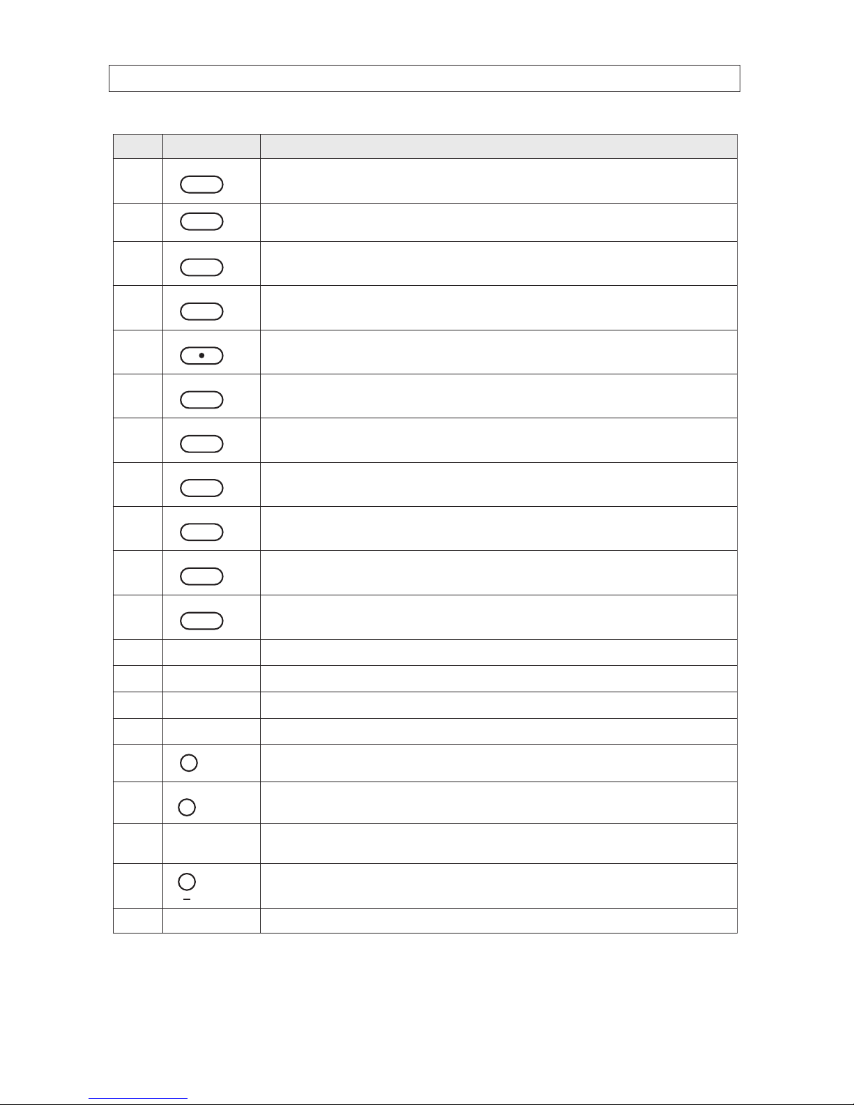
Table 2. Front Panel Buttons
No. Name Descript ion
1
Channel keys. For chann el 10, press the 0 key. For channel 11, press the +10 and 1 key. For channel 16, press the +10
and 6 key.
2
Press to rewind the vid eo in playback mode.
3
..
AUDIO
Press to selec t audio mode such as SINGLE (highlighte d channel), MIX (combin e all channels), or MUTE (all c hannels).
3H.264 DVR User Manual
No. Name Descript ion
4
..
AUDIO
Jump/step back ward. In playback mode, the play back position moves 60 seconds backward.
5
Press to fast forward the footage in playback m ode.
6
..
ALARM
Press to enable/disable ALARM operation.
7
..
ALARM
Jump/Step forward. In p layback mode, t he playback position moves 6 0 seconds for ward.
8
REC
Press to star t or stop manual recording.
9
/ ll
SEARCH
Press to open th e SEARCH menu in live display mode.
10
/ ll
SEARCH
Press to play/pause the recording in playb ack mode.
11
SETUP
Press to enter SE TUP menu.
12
SEQ
Enable/disable the automatic sequence display of channels in f ull screen, quad-split, and 9-split display mode.
13
PTZ
Press to contro l Pan/Tilt/ Zoom operations.
14
BACKUP
Press to capture live or playback mode v ideo in JPEG format.
15
t (LEFT)
Press to move lef t or to change the value s in Setup mode. When entering a p assword, it inserts a 4.
16
p (UP)
Press to move up th e menu in Setup mode. When entering a password, it insert s a 1.
17
u (RIGHT )
Press to move right or to change the values in Setup mode. When entering a p assword, it inserts a 2.
18
q (DOWN)
Press to move down the menu in Setup mode. When entering a p assword, it inser ts a 3.
19
SEL
Press to selec t desired menu item or to store the setup valu e.
20
ESC
Press f or temporar y storage of the changed value or to return to the previous menu scre en.
21 USB Port
Use with a USB ash drive to archive s till images and v ideos, and upgrade r mware, or use to connec t a USB mouse to
the DVR.
22
To open and close the inser t tray, press the button
23 DVD Drive To save vide o, insert a CD-R/DV D-R
SECTION 2: HARDWARE OVERVIEW AND SETUP
4
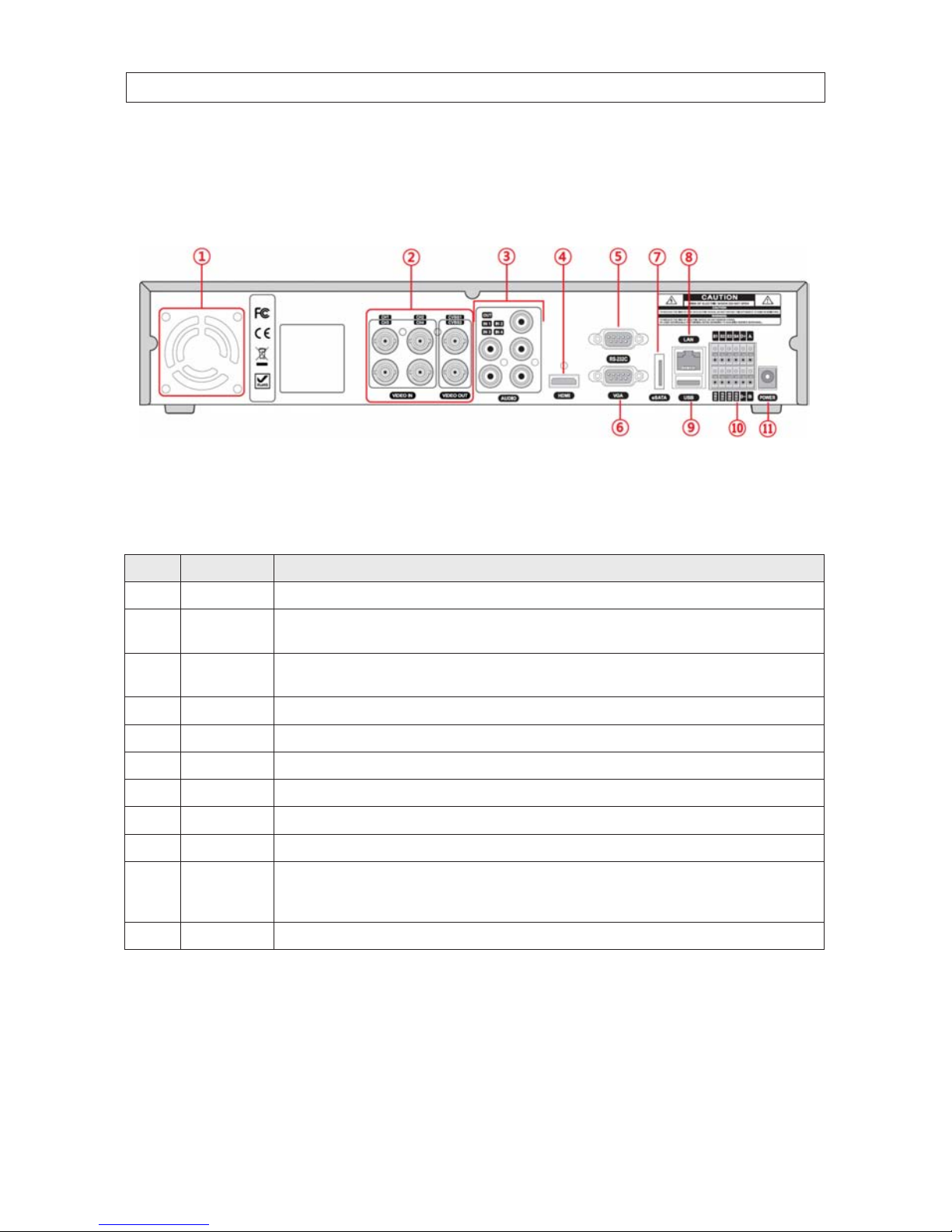
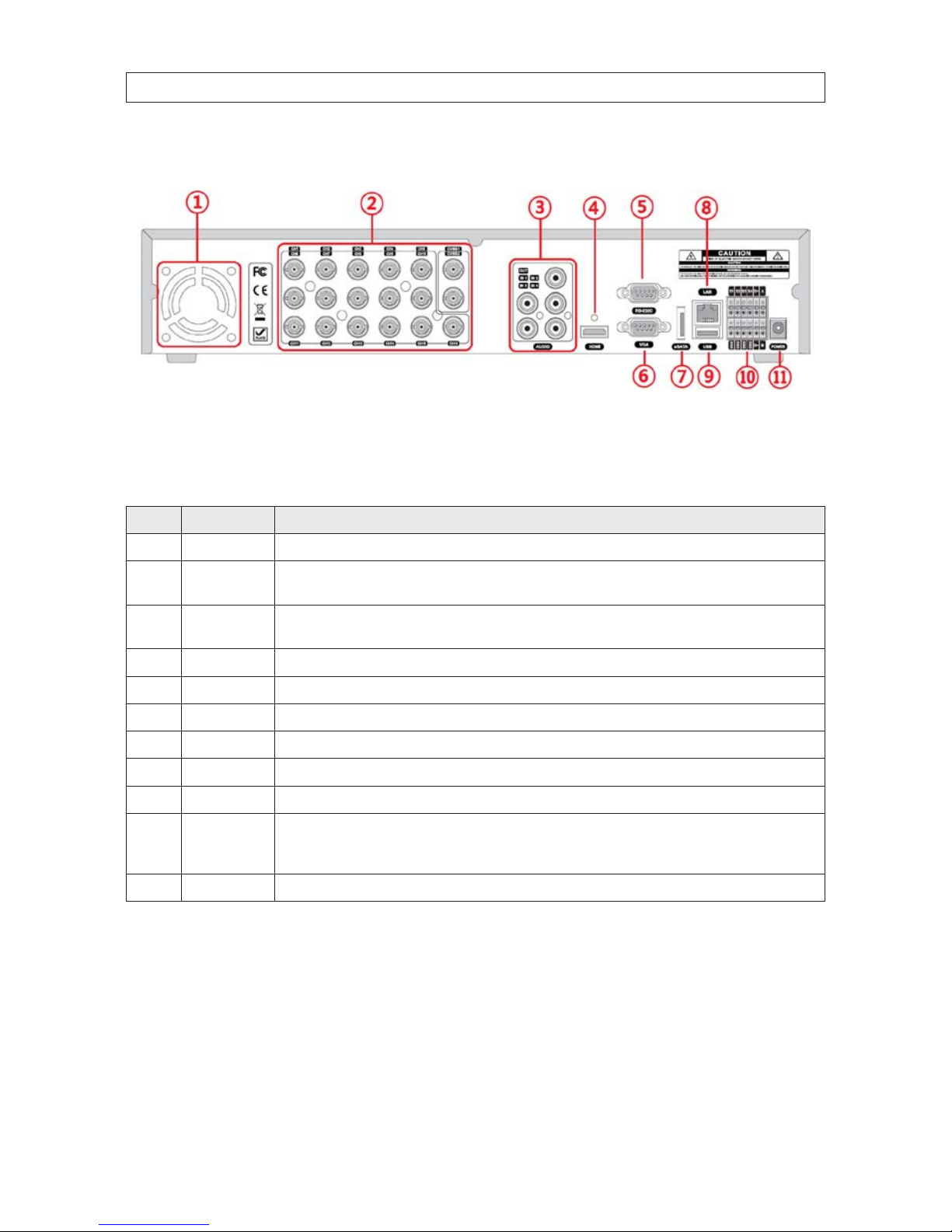
2.2 Back panel connectors
2.2.1 BLK-DH200400DHDVD
4-Channel DVR Rear Panel
Table 3. BLK-DH200400DHDVD Rear Panel Connectors
No. Name Descript ion
1 Fan Airow outlet
2
VIDEO IN
VIDEO OUT
4 BNC connectors for compo site video input
CVBS1, CVBS2 co mposite vide o output
3
AUDIO IN
AUDIO OUT
4 RCA connectors for audio input
1 RCA connector for audio ou tput
4 HDMI HDMI video out .
5 RS-232 interface Used for testing only. .
6 VGA Connec tor for a VGA monitor.
7 eSATA port Connector for external storage
8 ETHERNET RJ-45 connector f or LAN connec tion.
9 USB Use with a USB ash dr ive to archive st ill images and videos, and upgr ade rmware, or use to connect a USB mouse to the DVR
10
RS-485, sensor
and alarm
terminations
See description b elow.
11 POWER SO CKET Connec t DC12V 5A power adaptor
SECTION 2: HARDWARE OVERVIEW AND SETUP
5H.264 DVR User Manual
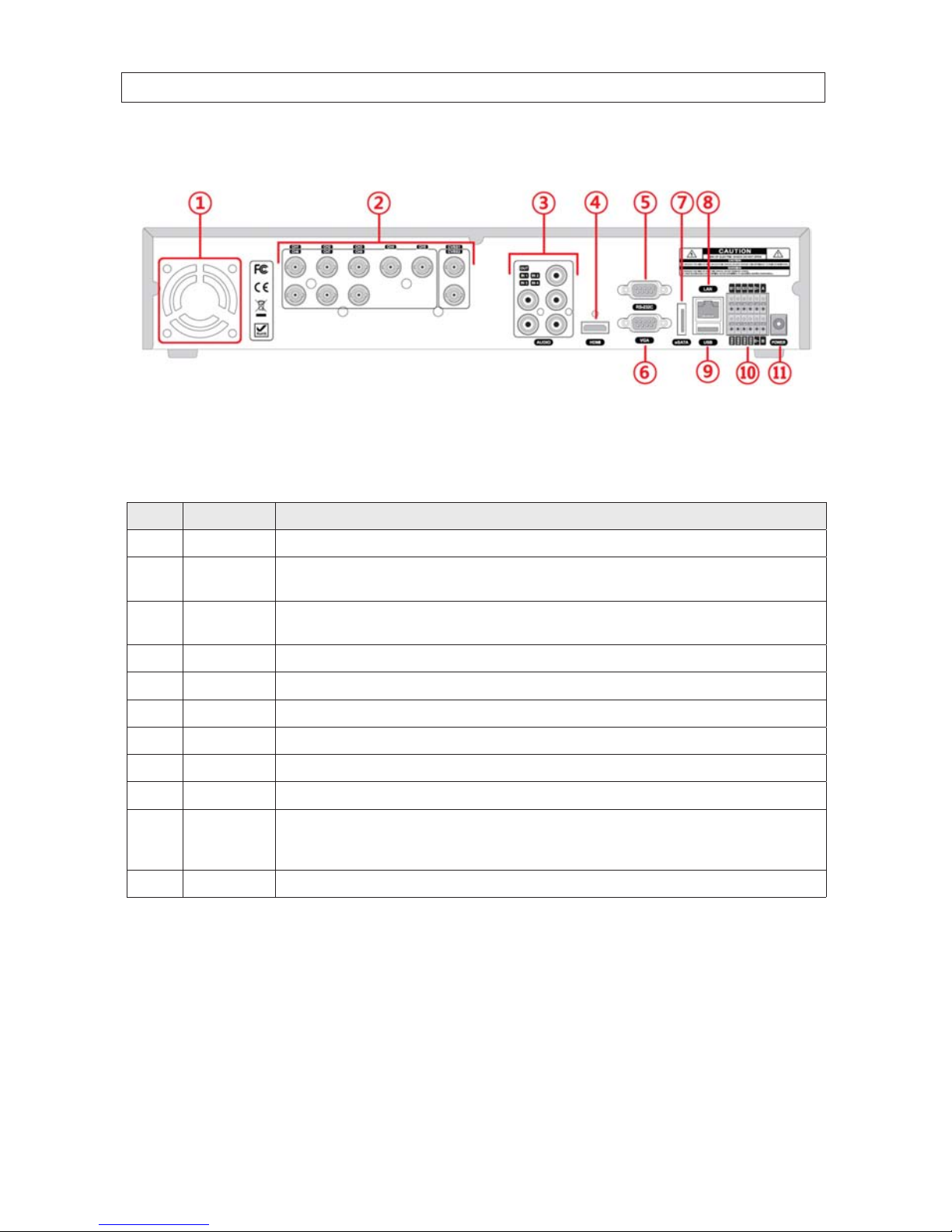
2.2.2 BLK-DH200800DHDVD
8-Channel DVR Rear Panel
Table 4. BLK-DH200800DHDVD Rear Panel Connectors
No. Name Descript ion
1 Fan Airow outlet
2
VIDEO IN
VIDEO OUT
8 BNC connectors for compo site video input
CVBS1, CVBS2 co mposite vide o output
3
AUDIO IN
AUDIO OUT
4 RCA connectors for audio input
1 RCA connector for audio ou tput
4 HDMI HDMI video out .
5 RS-232 interface Used for testing only. .
6 VGA Connec tor for a VGA monitor.
7 eSATA port Connector for external storage
8 ETHERNET RJ-45 connector f or LAN connec tion.
9 USB Use with a USB ash dr ive to archive st ill images and videos, and upgr ade rmware, or use to connect a USB mouse to the DVR
10
RS-485, sensor
and alarm
terminations
See description b elow.
11 POWER SO CKET Connec t DC12V 5A power adaptor
SECTION 2: HARDWARE OVERVIEW AND SETUP
6
2.2.3 BLK-DH201600DHDVD
16-Channel DVR Rear Panel
Table 5. BLK-DH201600DHDVD Rear Panel Connectors
No. Name Descript ion
1 Fan Airow outlet
2
VIDEO IN
VIDEO OUT
4 BNC connectors for compo site video input
CVBS1, CVBS2 co mposite vide o output
3
AUDIO IN
AUDIO OUT
4 RCA connectors for audio input
1 RCA connector for audio ou tput
4 HDMI HDMI video out .
5 RS-232 interface Used for testing only. .
6 VGA Connec tor for a VGA monitor.
7 eSATA port Connector for external storage
8 ETHERNET RJ-45 connector f or LAN connec tion.
9 USB Use with a USB ash dr ive to archive st ill images and videos, and upgr ade rmware, or use to connect a USB mouse to the DVR
10
RS-485, sensor
and alarm
terminations
See description b elow.
11 POWER SO CKET Connec t DC12V 5A power adaptor
SECTION 2: HARDWARE OVERVIEW AND SETUP
7H.264 DVR User Manual
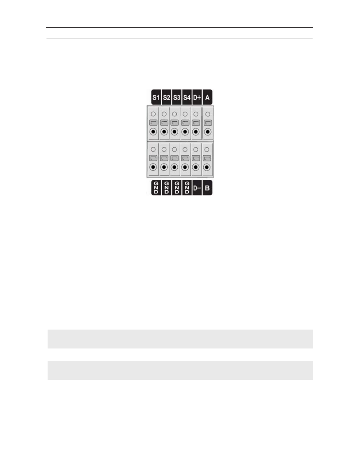
2.2.4 RS485, sensor and alarm termination block
Use the back panel termination block to connect sensor, RS-485, and alarm out cables.
Pin block denitions:
S1, GND: Sensor 1 input
S2, GND: Sensor 2 input
S3, GND: Sensor 3 input
S4, GND: Sensor 4 input
D+, D-: RS-485A and RS-485Bt
A, B: Alarm output
NOTE
S1 - S4 sensor inputs can be normally open (N.O.) or normally closed (N.C.). To congure the sensor type, go to
SETUP -> Device -> Sensor: Type. .
NOTE
A - B (alarm out) can be triggered by any single of combination of sensors and motion on or video loss in up to four camera
channels. To congure alarm causing conditions, go to: SETUP -> Device -> Alarm Out.
SECTION 2: HARDWARE OVERVIEW AND SETUP
8
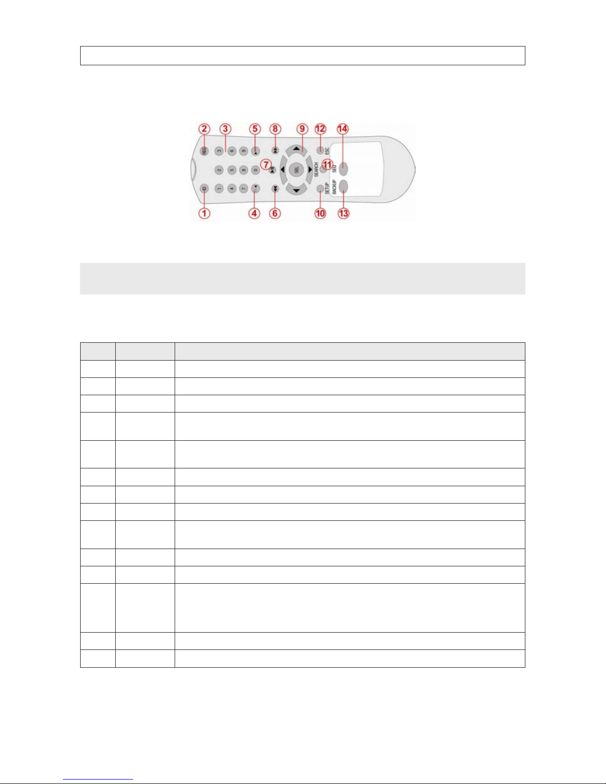
2.3 Remote Control
Typical Remote Control
NOTE
The remote control provided with your DVR may appear dierent from the one shown above. However, the buttons function as
described in the table below.
Table 6. Remote Control Button Functions
No. Name Function
1 ID When a remote control ID number is se tup in DVR, press this bu tton before the number.
2 REC To start and s top manual recording.
3 0 .. 9 To select channel (1, 2, 3, ..) or to enter a DVR ID number.
4 F/REW
During Playback – To move the p layback position 60 secon ds back.
During Pause – To move the playback position 1 frame back.
5 F/ADV
During Playback – To move the p layback position 60 secon ds forward.
During Pause – To move the playback position moves 1 frame for ward.
6 REW To rewind the recordin g. Press again to increas e the rewind speed.
7 PLAY/PAUSE To play or to pause the recording in playb ack mode.
8 FF To fast forward the recording. Pre ss again to increase the fast f orward spe ed.
9
Direc tion
Buttons
Press to move to menu items or select a channel.
10 SETUP To open the SETUP menu.
11 SEARCH To go to the SEARCH menu.
12 ESC
During setup – To return to the previous menu screen.
During playback – To exit p layback mode
System lock – To lock a s ystem when pressin g ESC button f or 5 seconds.
System unlock – To unlock a sy stem when pressing ESC but ton for 5 seconds.
13 BACKUP To start a backup operations in live or playback mode.
14 SEQ To start au to sequencing the screen in f ull screen mo de. (Toggle)
SECTION 2: HARDWARE OVERVIEW AND SETUP
9H.264 DVR User Manual
2.4 DVD-R/W Optical drive installation
If your DVR does not include an internal DVD-R/W drive, use the following procedure to install one. The DVD-R/W can be used to
archive stored data including video clips and snapshots. Your DVR will accommodate one standard-size desktop system DVD-R/W
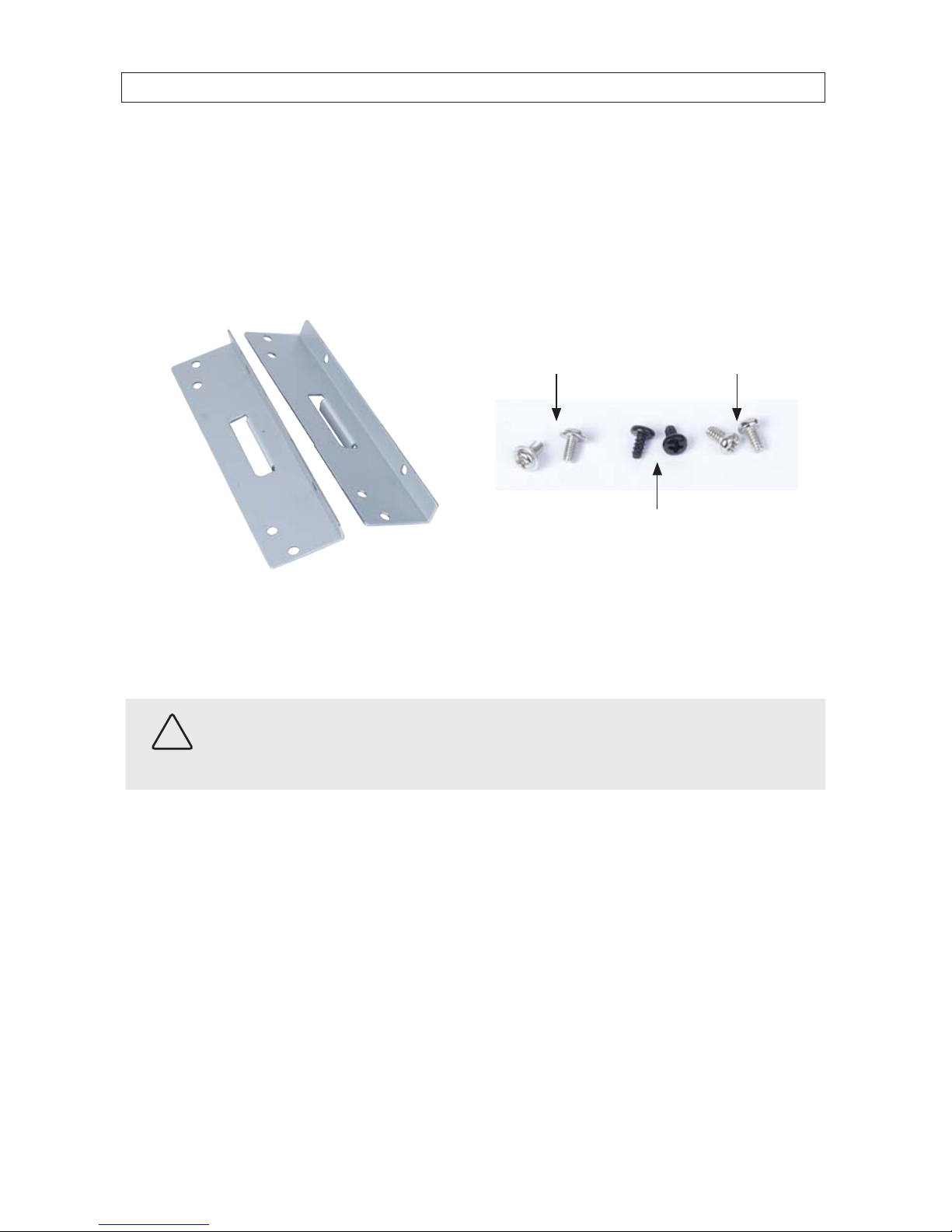
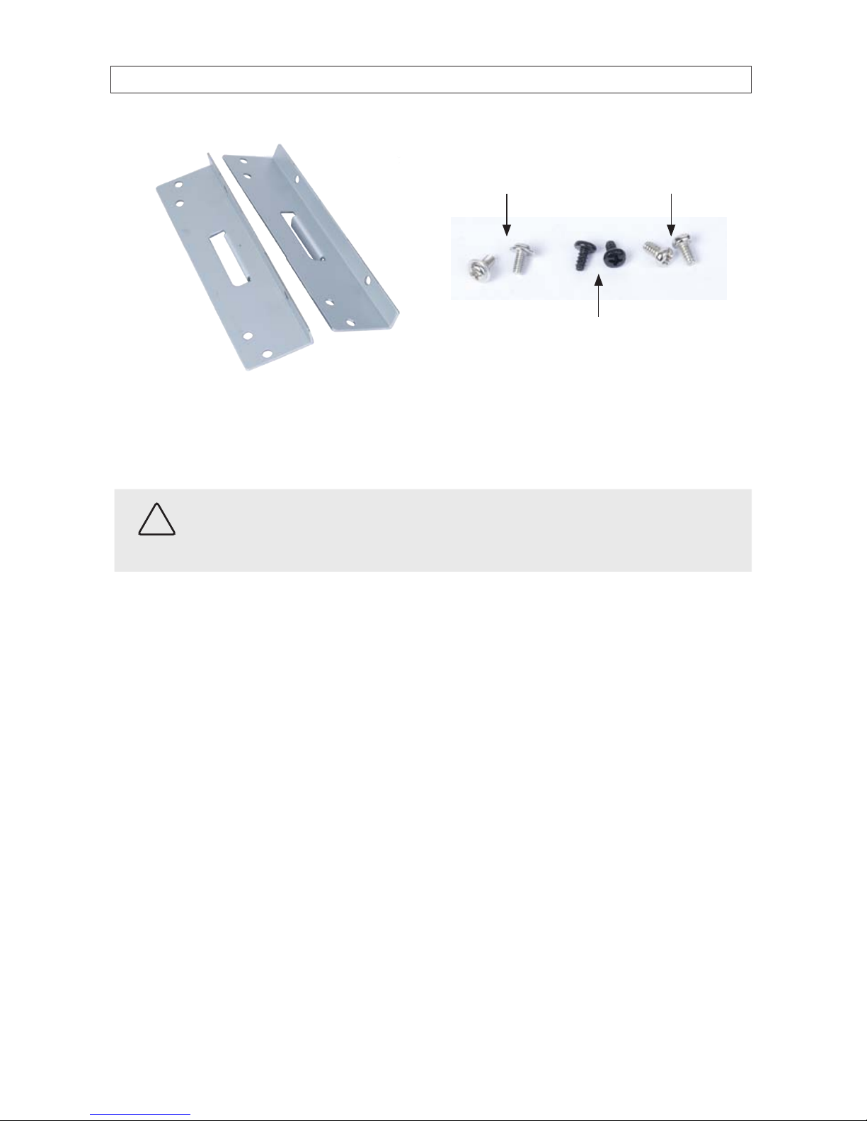
drive with a serial-ATA (SATA) interface. If your DVR was purchased without a DVD-R/W drive or HDD drive, a hardware kit,
including mounting brackets, screws and cables is included with the DVR.
For attaching bracket
to DVD-R/W (at-head,
ne-thread screws (4))
For attaching bracket to
HDD (pan-head, medium-
thread screws (4))
For attaching bracket
to chassis (pan-head,
course-thread screws)
Mounting brackets (one pair per drive) Screw types
To install a DVD-RW drive, carefully follow the procedure below. Although this procedure is illustrated for a 16-channel DVR, it is
identical for a 4- or 8-channel DVR.
CAUTION
Follow recommended electrostatic discharge (ESD) guidelines while performing this procedure. Install the DVD-R/W drive in
a static-free environment, wearing a certied ESD wrist strap. If a static free environment and ESD wrist strap is not available,
touch the bare metal of the DVR chassis frequently when installing the drive to dissipate the static charge naturally generated
on your skin and clothing. .
1. If your DVR is powered on, use the menu system to perform a System Shutdown.
a. Right click anywhere on the live view screen, then click SYSTEM SHUTDOWN in the pop-up menu (see “3.1 Starting
the system for the rst time” on page 17), or click the SYSTEM SHUTDOWN icon on the taskbar.
b. Follow the on-screen instructions for shutting down the system.
2. Disconnect the power adapter from the back of the DVR.
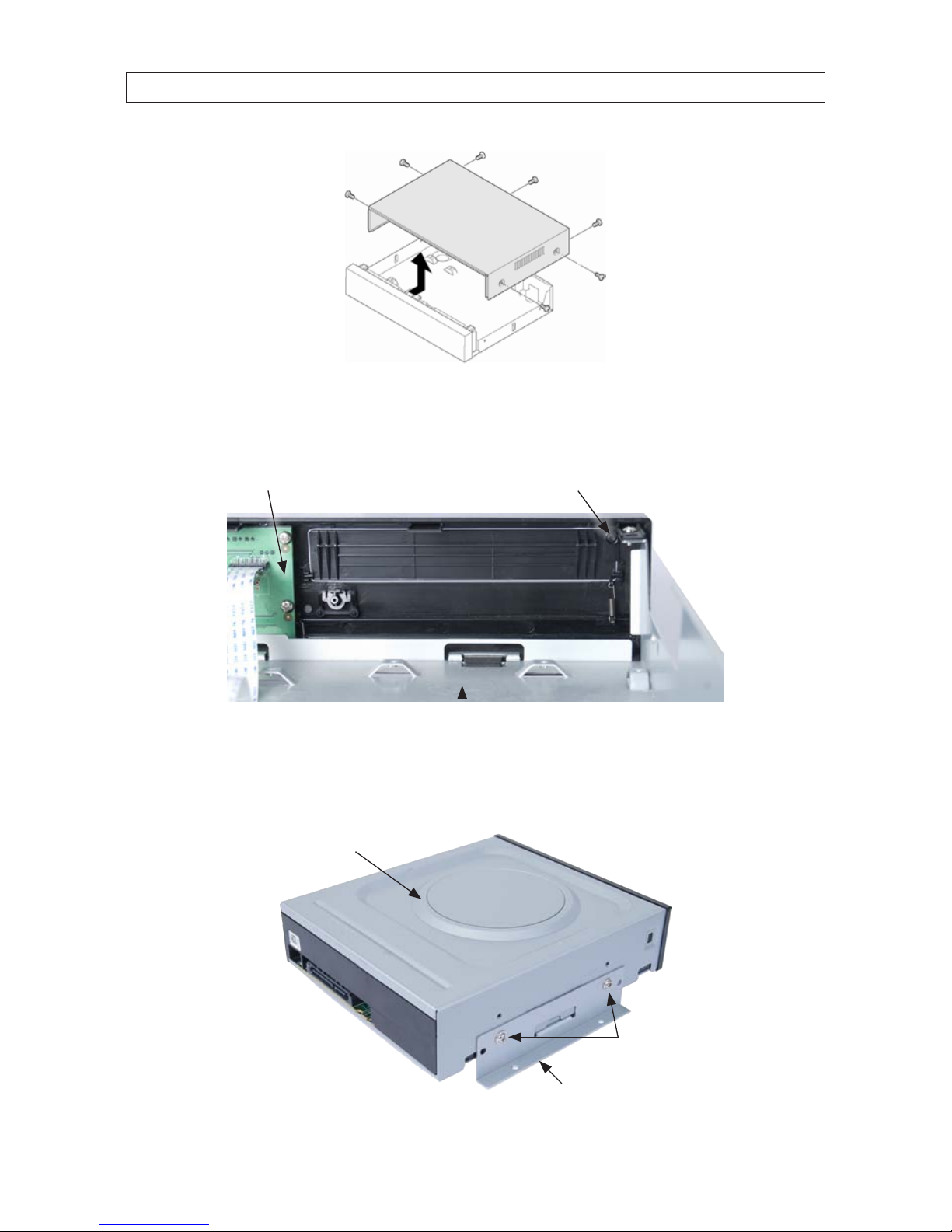
3. Remove the top cover from the DVR by removing the three cover screws on the back of the chassis, and the two on each side.
See the drawing below.
SECTION 2: HARDWARE OVERVIEW AND SETUP
10
SECTION 2: HARDWARE OVERVIEW AND SETUP
4. Remove the optical drive tray door retain screw from the inside of the DVR front panel. See the picture below. Use a #1
Phillips screwdriver.
Optical drive tray door
retaining screw location
Back side of
DVR front panel
Optical drive bay
5. Attach a mounting bracket to each side of the DVD-R/W drive as shown below using the at-head ne thread screws
provided. Use two screws for each bracket. Tighten the screws until snug.
DVD-R/W drive
Mounting bracket
Flat-head ne-thread
screws (2)
11H.264 DVR User Manual
SECTION 2: HARDWARE OVERVIEW AND SETUP
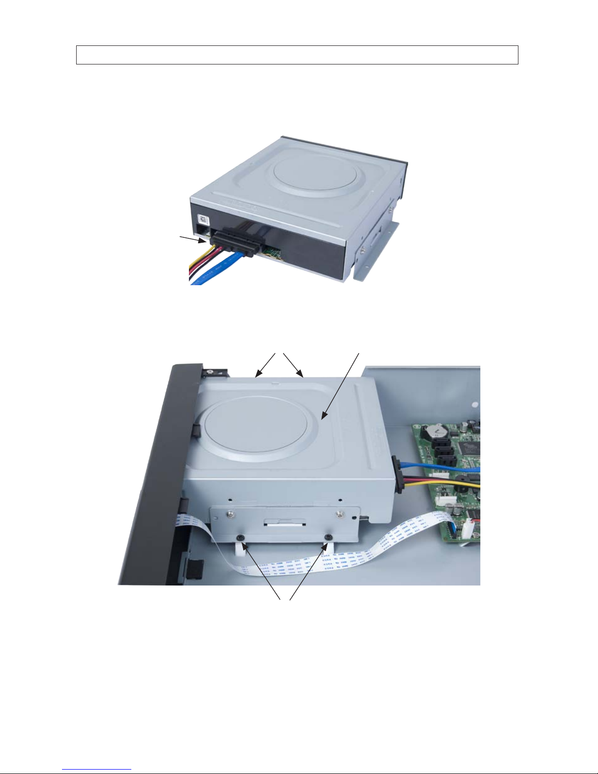
6. Plug a SATA data and power cable assembly into the mating connectors on the back of the DVD-R/W drive. Ensure the
connector is fully seated.
SATA data and
power cable
7. Position the DVD-R/W drive in the optical drive bay as shown below. Secure the drive to the chassis with four screws through
the mounting brackets, two on each side. Use black pan-head course-thread screws provided. Tighten the screws until snug.
DVD-R/W drive in optical drive bayScrews
Screws
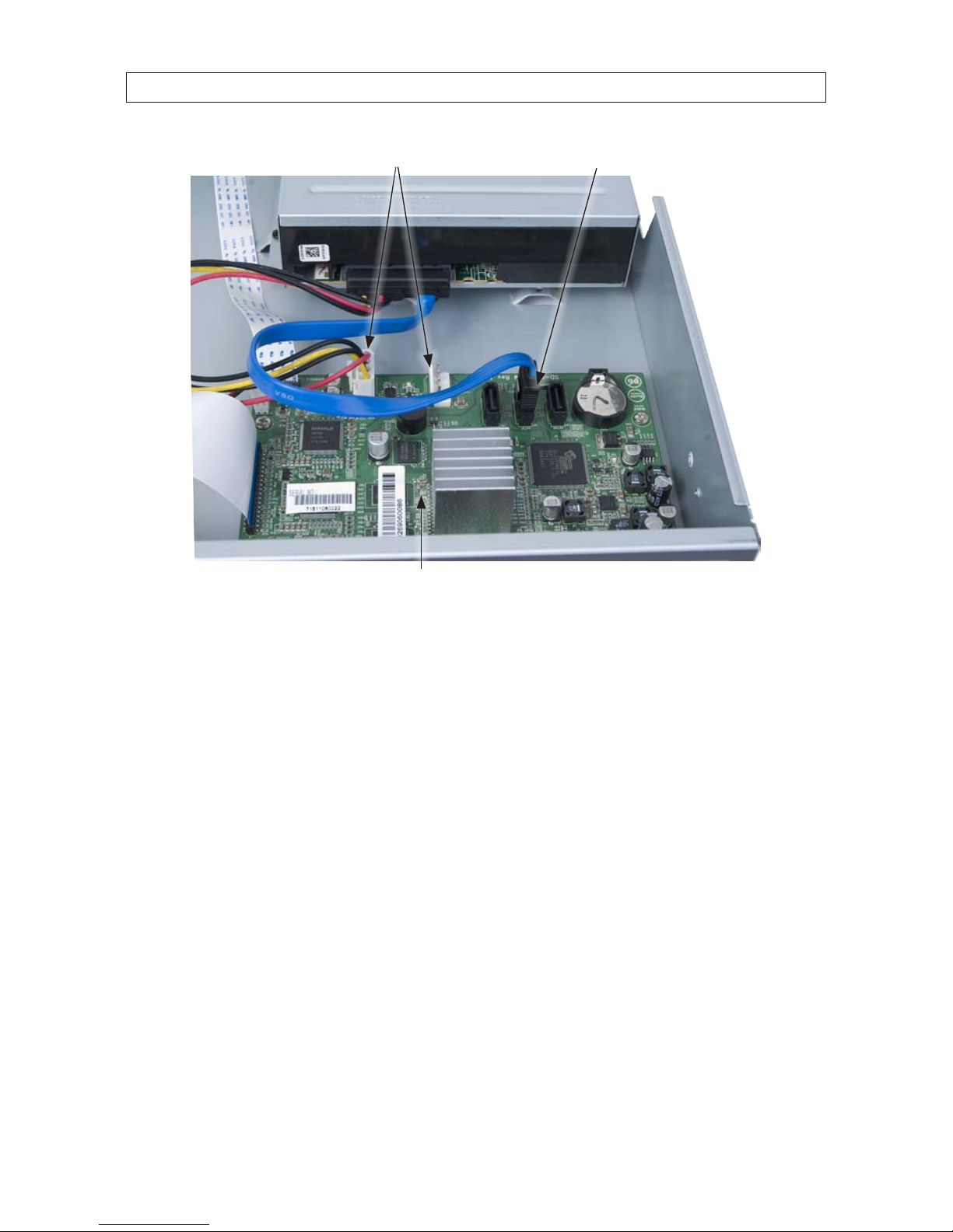
8. Plug the SATA data cable (blue cable) into the SATA1 connector on the PC board, then plug the SATA power cable into one of
the SATA power connectors on the PC board.
12
SECTION 2: HARDWARE OVERVIEW AND SETUP
SATA1 connector
SATA power connectors
PC board
Ensure that the data and power cable connectors are fully seated onto the connectors on the PC board.
9. Reinstall the DVR cover using the 7 screws removed earlier.
10. Reattach the power adapter to the back of the DVR.
2.5 HDD installation
The HDD is used to store video and snapshots recorded by the DVR. Normally, DVRs have one internal HDD and one internal DVDR/W drive. However, a second internal HDD can be installed in place of the DVD drive, if needed.
Your DVR will accommodate one standard-size desktop system HDD with a SATA interface. When choosing an HDD to install, select
one from the list provided in “APPENDIX A DVR Compatible Hard Disk Drives” on page 104 to ensure the best performance. If your DVR
was purchased without an HDD, a hardware kit, including mounting brackets, screws and cables is included with the DVR.
13H.264 DVR User Manual
SECTION 2: HARDWARE OVERVIEW AND SETUP
13
For attaching bracket
to DVD-R/W (at-head,
ne-thread screws (4))
For attaching bracket to
HDD (pan-head, medium-
thread screws (4))
For attaching bracket
to chassis (pan-head,
course-thread screws)
Mounting Brackets (one pair per drive) Screw types
To install an HDD, carefully follow the procedure below. Although this procedure is illustrated for a 16-channel DVR, it is identical for
a 4- or 8-channel DVR.
CAUTION
Follow recommended electrostatic discharge (ESD) guidelines while performing this procedure. Install the HDD in a static-free
environment, wearing a certied ESD wrist strap. If a static free environment and ESD wrist strap is not available, touch the bare
metal of the DVR chassis frequently when installing the drive to dissipate the static charge naturally generated on your skin and
clothing. .
1. If your DVR is powered on, use the menu system to perform a System Shutdown.
a. Right click anywhere on the live view screen, then click SYSTEM SHUTDOWN in the pop-up menu (see “3.1 Starting
the system for the rst time” on page 17), or click the SYSTEM SHUTDOWN icon on the task bar.
b. Follow the on-screen instructions for shutting down the system.
2. Disconnect the power adapter from the back of the DVR.
3. Remove the top cover from the DVR by removing the three cover screws on the back of the chassis, and the two on each side.
See the drawing below.

14
SECTION 2: HARDWARE OVERVIEW AND SETUP
4. Attach a mounting bracket to each side of the HDD as shown below using the pan-head medium- thread screws provided.
Use two screws for each bracket. Tighten the screws until snug.
HDD
Mounting bracket
Pan-head mediumthread screws (2)
5. Plug a SATA data and power cable assembly into the mating connectors on the back of the HDD. Ensure the connector is fully
seated.
SATA data and
power cable

15H.264 DVR User Manual
SECTION 2: HARDWARE OVERVIEW AND SETUP
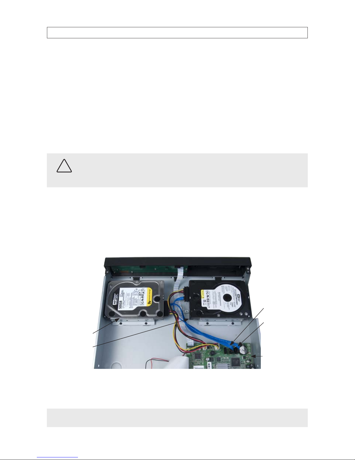
6. Position the HDD into the HDD bay as shown below. Secure the drive to the chassis with four screws through the mounting
brackets, two on each side of the HDD. Use black pan-head course-thread screws provided. Tighten the screws until snug.
Screws (2) between HDD and
back of DVR front panel
Screws
DVR front panel
DVD-R/W drive
7. Plug the SATA data cable (blue cable) into the SATA0 connector on the PC board, then plug the SATA power cable into one of
the SATA power connectors on the PC board.
SATA0 connectorSATA power connectors
PC board
HDD
16
SECTION 2: HARDWARE OVERVIEW AND SETUP
Ensure that the data and power cable connectors are fully seated onto the connectors on the PC board.
8. Reinstall the DVR cover using the 7 screws removed earlier.
9. Reattach the power adapter to the back of the DVR.
2.5.1 Installing a 2nd internal HDD
The DVR can include two internal HDDs, with the second HDD installed in the DVD-R/W (optical) drive bay. To install a 2nd HDD, do
the following.
CAUTION
Follow recommended electrostatic discharge (ESD) guidelines while performing this procedure. Install the HDD in a static-free
environment, wearing a certied ESD wrist strap. If a static free environment and ESD wrist strap is not available, touch the bare
metal of the DVR chassis frequently when installing the drive to dissipate the static charge naturally generated on your skin and
clothing.
1. If a DVD-RW drive is installed in the optical drive bay, remove it by reversing the procedure included above in “2.4 DVD-R/W
Optical drive installation” on page 9.
2. Attach the mounting brackets and data/power cable to the 2nd HDD. See “2.5 HDD installation” on page 12 above.
3. Position the HDD in the optical bay as shown below, and attach it to the chassis using 4 screws, 2 on each side.
SATA1 connector
SATA0 connector
Primary HDD
Secondary HDD
PC board
4. Connect the HDD SATA data cable (blue) to the SATA1 connector on the PC board.
5. Connect the HDD SATA power cable to one of the mating connectors on the PC board.
NOTE
In a DVR with 2 HDDs, the primary HDD is connected to the SATA0 connector and the secondary HDD is connected to the SATA1
connector.
17H.264 DVR User Manual
SECTION 3: SYSTEM SETUP
SECTION 3
System Setup
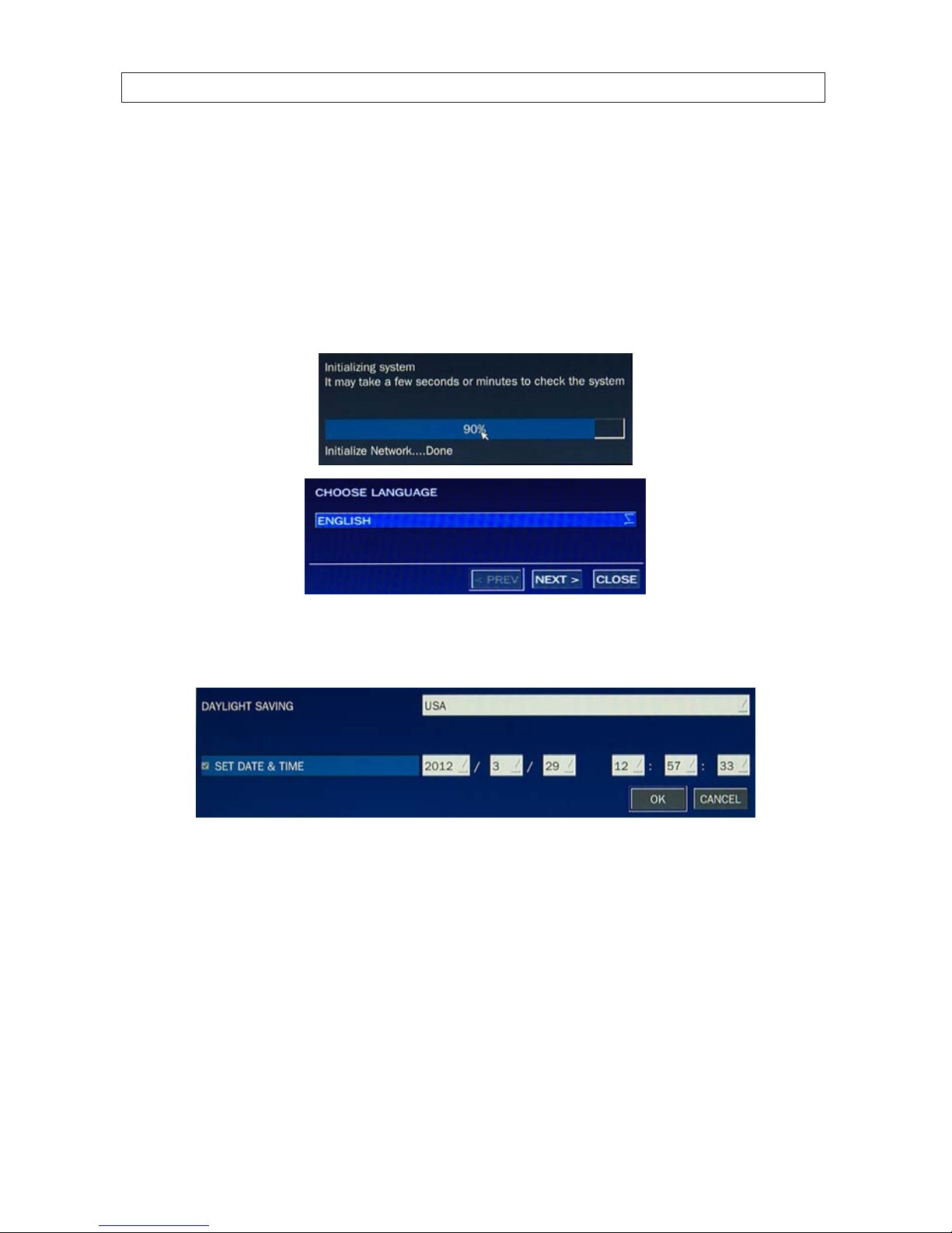
3.1 Starting the system for the rst time
When booting the system for the rst time, the following messages appear. After the initialization sequence completes, select your
preferred language and set the date and time.
When the Set date and time window opens, use the dropdown lists to show the correct date and time, then click Finish. The
date and time setting is used to timestamp recordings.

18
SECTION 3: SYSTEM SETUP
Typical System Desktop Display With One Camera Active
3.1.1 Entering the SETUP menu
6. To enter the SETUP menu, right click on the desktop or
press the SETUP button on the remote control, then click
the SETUP
entry in the pop-up menu. A LOGIN window
will open.
7. In the LOGIN window, open the virtual keyboard and enter the PASSWORD, or use the direction buttons on the front panel.
The default password is “1111”.
Virtual
Keyboard
Button
After entering the password, the SETUP window will open.
19H.264 DVR User Manual
SECTION 3: SYSTEM SETUP
NOTE
For improved security, change the password. You can select a new password through the SECURITY tab in the SETUP menu.
Open a menu by clicking the tab. To close the window, click Cancel. To save changes made to the menus before closing the
window, click OK.
For a summary of the elements in each SETUP submenu (tab), refer to Appendix C.
Navigating the menus
You can navigate through the menu system, change option values, and click buttons with the mouse. Entry elds usually
have drop-down menus you can open to select preset parameter values. Other parameters elds open submenus or
keyboards you can use to enter names and other values. You can also navigate through the menu items using the direction
button, p, q, t, or u and change option values with the SEL button. Always select (or click) OK to save new settings
and close the SETUP menus. Press the ESC button at any time to exit the SETUP menus.
NOTE
In the following descriptions of the SETUP menus, the instructions for navigating the system includes use of the front panel
buttons only. Using a mouse for menu navigation and setup of system options can be easier and faster.
20
SECTION 3: SYSTEM SETUP
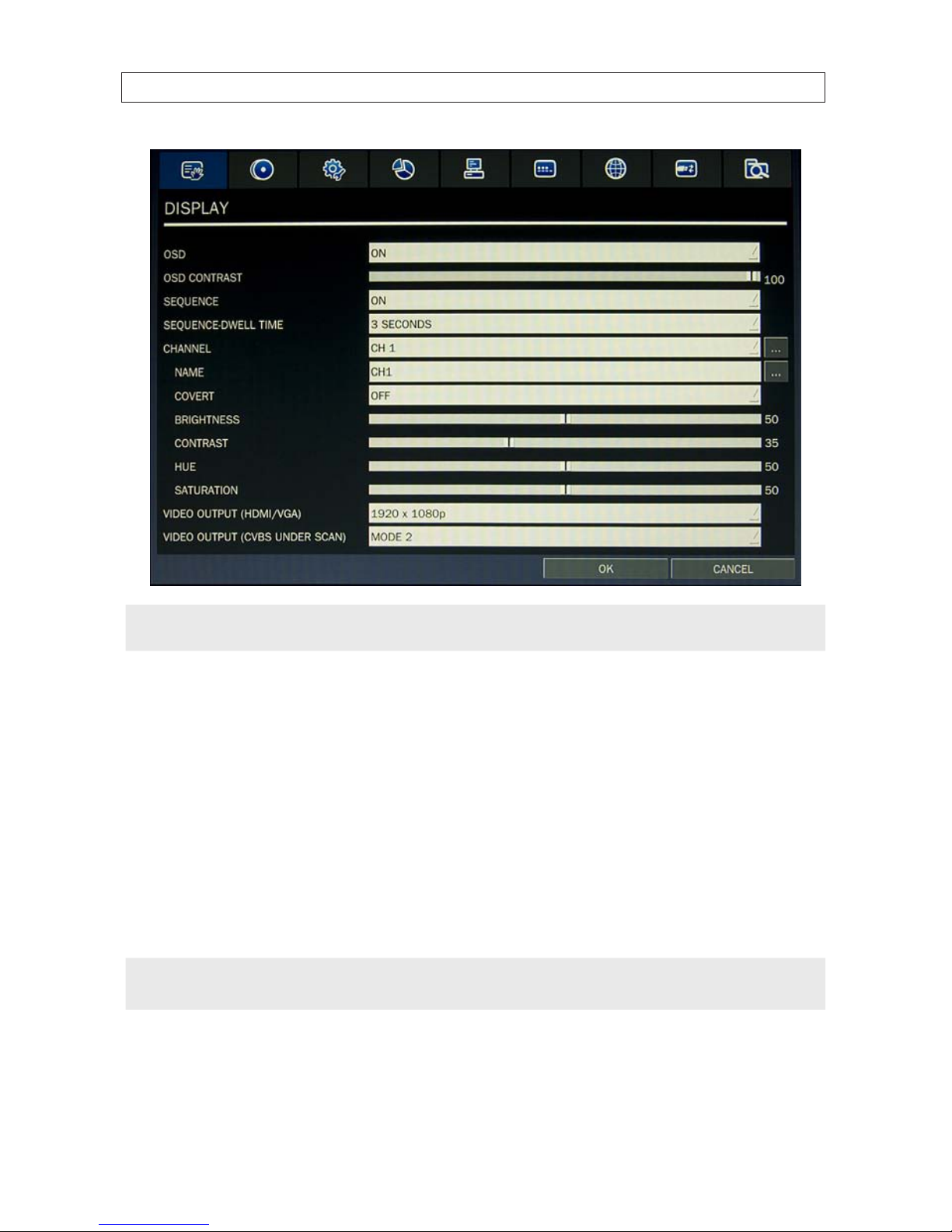
3.2 DISPLAY menu
Opening the SETUP menu, or clicking the DISPLAY tab, opens the DISPLAY menu.
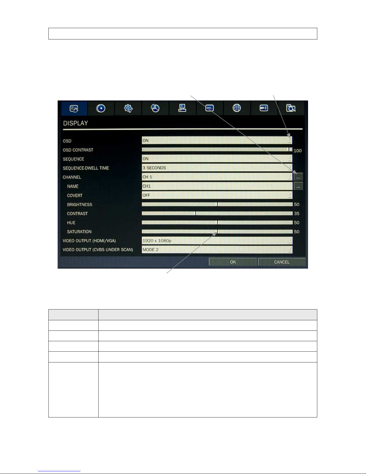
Open Submenu
Drag to adjust
Open Drop-down List
Table 7. DISPLAY menu options
Item Descript ion
OSD Enable/disable the on-screen display.
OSD CONTR AST Set the visibili ty level of the OSD. (0 ~ 100)
SEQUENCE Enable/disable sequential display of video in full screen mode.
SEQ-DWELL TIME Set the dwell time of each quad-split or 9 -channel display in se quential display mode. (3 - 60 seconds)
CHANNEL In the channel submenu, yo u can tune the display settings for all cameras at once, or setup each c amera individually. Click the
channel drop-down list to selec t the channel, then use the click t he submenu but tons to NAME the c hannel and set the COVERT
propert y (enable/disab le live display mod e). Drag the marker on the image adju stment bars to per fect the image.
BRIGHTNESS: Change the b rightness value of th e selected c hannel. (0 ~ 100)
CONTRA ST: Change the contras t value of the selected channel. (0 ~ 100)
HUE: Change the hue value of the selected channel. (0 ~ 100)
SATURATION: Change the saturation value of the selected channel. (0 ~ 100)
Click
OK to save t he setting s and close the window.
21H.264 DVR User Manual
SECTION 3: SYSTEM SETUP
Item Descript ion
VIDEO OUTPUT ( VGA) Click the submenu but ton to open a list of monito r resolutions, then c lick the resolution you prefer. Click OK.
VIDEO OUTPUT
(CVBS UND ER SCAN)
TBS.
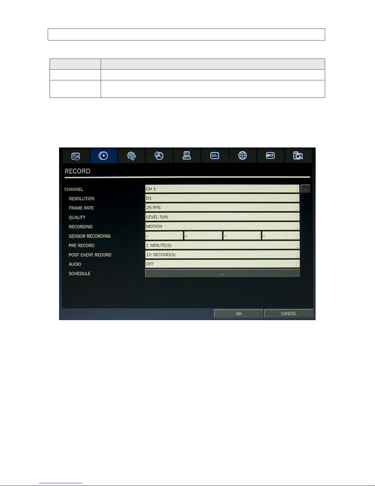
3.3 RECORD menu
Clicking the RECORD tab opens the RECORD menu.
22
SECTION 3: SYSTEM SETUP
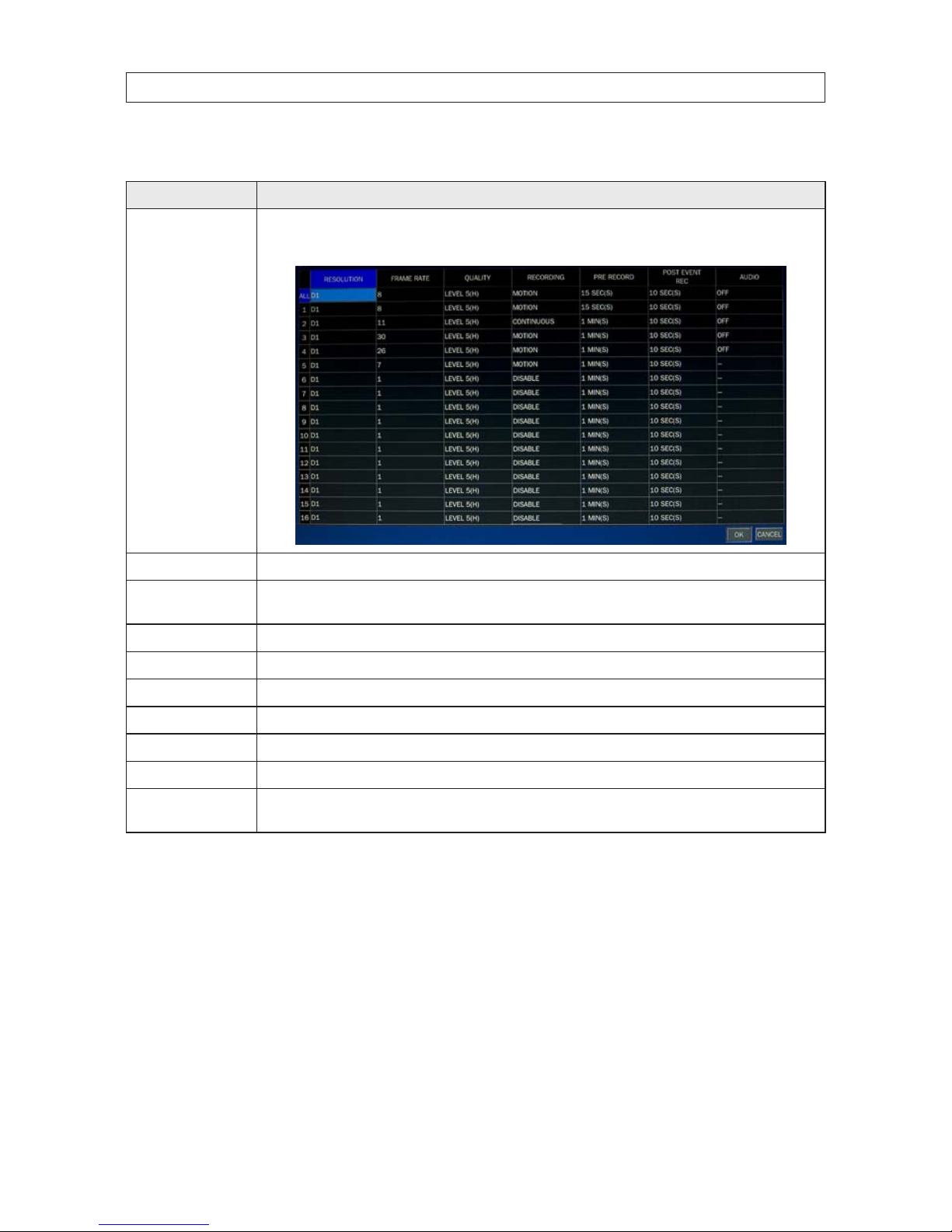
Table 8. Menu Items in Recording Mode Setup
Menu Item Description
CHANNEL In the Record Channel submenu, you can set the recording modes fo r all cameras at once, or setup each camera individually.
Click th e submenu button to open the setup window. Clic k a eld to highlight it, clic k the down arrow in the eld, then s elect the
option you want f rom the drop-down menu. Click
OK to save t he setting s and close the window.
RESOLUTION Select either CIF, Half D1, or D1.
FRAME RATE Set the f rame rate for the specied channel (1 ~ 30 fps). The sum of the f rame rates fr om each channel cannot exceed t he maxi-
mum frame rate s for a specic recording resolution. See the Sp ecications section for the maximum video frame o f your r ecorder.
QUALIT Y Selec t the recording quality for the specied channel (Level 1 (low) to Level 5 (high)).
RECORDING Assign the recording mode for each channel. Options are: Disable, Continuous, Motion,Sensor,Schedule.
PRE RECORD Enable/disable pre-event re cording. Opti ons are OFF, 15 SEC, 30 SEC, 1 MIN, 3 MIN, 20 MIN. .
POST EVENT RE CORD Set the post event recording time duration for the specied c hannel. (10 ~ 60 seconds)
SENSOR R ECORDING Enable setting up to 4 sensor s for the specied c hannel.
AUDIO Enable/disable audio recording for channel 1 .. 4 only.
SCHEDULE Click the submenu icon to open the re cording schedule se tup window. To congure this feature, s ee the sub-sect ion Recording
Schedules below.
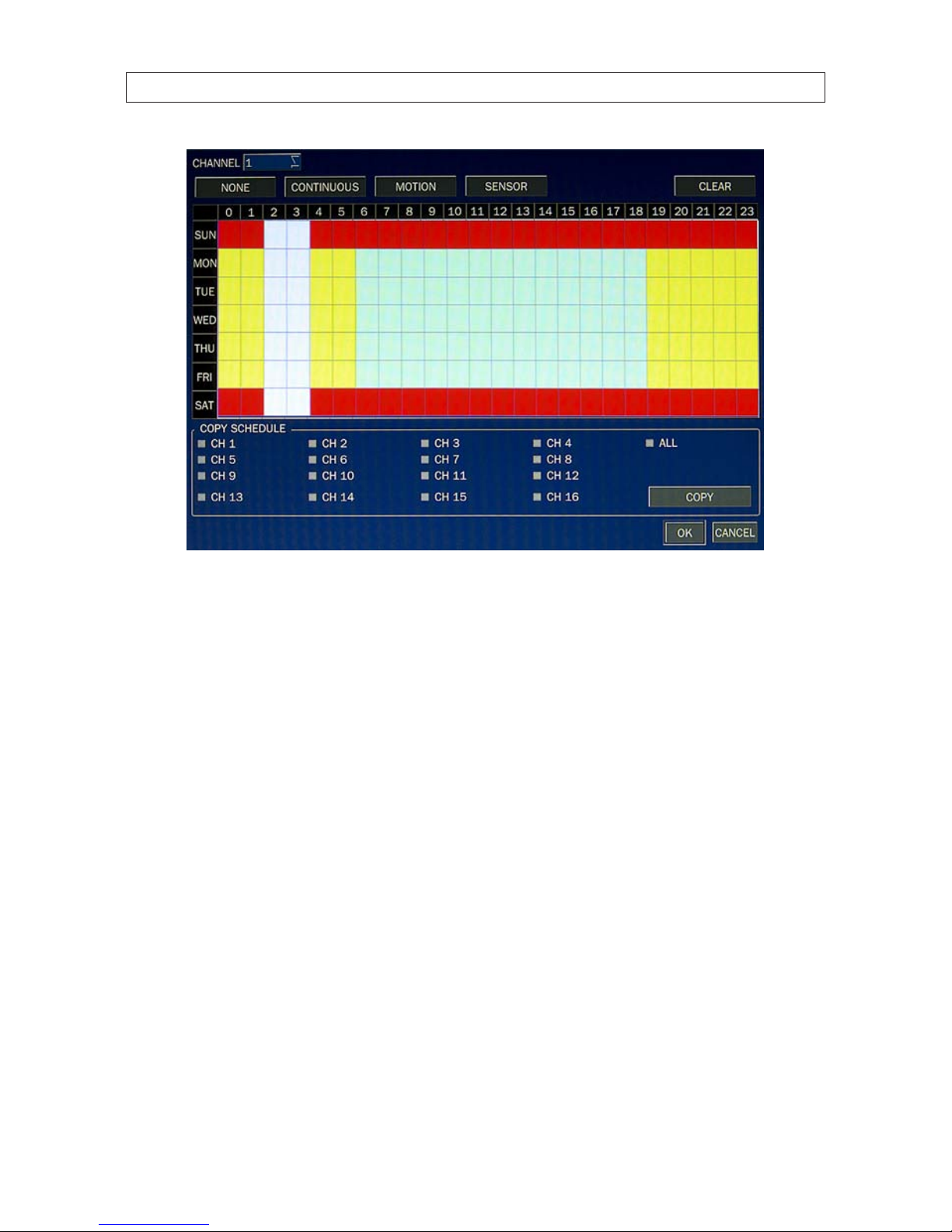
3.3.1 Recording Schedules
To setup a weekly recording schedule, click the SCHEDULE submenu bar in the RECORD menu. A recording mode (NONE,
CONTINUOUS, MOTION, or SENSOR) can be applied to any hour of the week for each camera.

23H.264 DVR User Manual
SECTION 3: SYSTEM SETUP
[CHANNEL]: Select the channel for the schedule you are setting.
[MODE]: Click the recording mode (NONE, CONTINUOUS, MOTION, or SENSOR) to apply to the schedule, then drag the mouse cursor
across the days and hours in the grid you where you want to use that mode. Timeslots are color coded for the record mode applied
to them: CONTINUOUS - green, MOTION - yellow, and SENSOR - red, NONE - white.
[COPY SCHEDULE]: To copy the schedule you setup to other cameras, click the camera channel number(s), then click COPY. You can
also use the front panel buttons,
p, q, t, u, and SEL buttons to perform these selections.
Click OK to save your settings, or press ESC to return to the RECORD menu.
24
SECTION 3: SYSTEM SETUP
3.4 DEVICE menu
Clicking the DEVICE tab opens the DEVICE menu. To return to SETUP menu, press the ESC button.

25H.264 DVR User Manual
SECTION 3: SYSTEM SETUP
Table 9. Menu Items in Device Setup Screen
Item Descript ion
ALARM OUT S et the sensor, mot ion, and video loss for each alar m.
ALARM OUT: 1 only.
SENSOR IN: Enable alarm out by sens or (up to 4 inputs).
MOTION ON: Enable alarm ou t by camera motion (up to 4 cameras can be monitored).
VIDEO LOSS ON: Enable alarm out by cam era video loss (up to 4 camer as can be monito red).
ALARM DURATION: S et the alarm dwell time. (5 ~ 6 0 seconds or innite (cont inuous)).
ERROR ALARM: Set the er ror type for the alar m activation. (OFF, ALL, HDD ERROR , VIDEO LOSS).

26
SECTION 3: SYSTEM SETUP
Item Descript ion
CONTROLLER AND PTZ To control the PTZ f unctions of the camera, connec t the PTZ controller to th e RS-485 po rt on the back of the chassis with
CAT 5 (or equivalent) cable. Setup the CONTROLLER AND PTZ submenu SPEED and ID to match t he controller an d camera
conguration.
CHANNEL: Channel conne cted to a PTZ device
NAME: Protocol type
SPEED: Baud rate: 19200, 14400, 96 00, 4800, 240 0
ID: 0 ~ 63
SPOT OUT Enable/disable display of the channel when an event is active.
SPOT ON EVENT: Enable/disable display of the channel wh en an event is active..
SPOT EVENT DWELL TIME: Set t he dwell time for the event act ivated channel (1 - 10 sec).
SEQUENCE: Enable/disable sequential display of spot c hannel(s) in full screen. If ON is selected, the spot channel is
displayed.
SEQUENCE-DWELL TIME: Set t he dwell time for the spot channel display (1-10 sec).
SPOT CHANNEL: Select a channel for spot monitoring. Press SEL and selec t channel using the p, q, t, and u buttons,
then press SEL.
CHANNEL Selec t specied channel for motion zone setup.

27H.264 DVR User Manual
SECTION 3: SYSTEM SETUP
Item Descript ion
MOTION ZONE Selec t either Full Zone or Par tial Zone for motion sensing.
FULL ZONE: The motion sens or is active on t he whole scre en. Set the level of sensi tivity for MOTION SENSITIVITY.
PARTIAL ZONE: Selec ting Partial Zone f or the channel, then clicking the submenu but ton, opens a widow containing the
camera image overlaid w ith a 22 x 15 block area s. You can s elect motion sensing for t he blocks in the areas individually
by click ing on them, or you c an select a larger area by dragging the mouse cu rsor across a rectangle of blocks. Block areas
selec ted for motion sensing are shaded green. To dis able motion sensing on a s elected block, click on it.
To return to the Device menu, right c lick on the scre en, or press the E SC button on the front panel.
MOTION SE NSITIVITY Set the motion sensit ivity for the specied channel. (1 ~ 9).
KEY TONE Enable/dis able tone when key is pressed.
REMOTE CONTROL ID Selec t an ID for the remote control dev ice.
1. Selec t ID number.
2. On the remote control, press the same number a s the ID set in the DVR.
3. An icon will be displayed on L ive screen that corresponds to the remote control. (0 ~ 99)
SENSOR Selec t sensor numb er. (1 .. 4)
TYPE Set the type of sensor for the specie d channel. (OFF, N/O (normal op en), N/C (normal clos ed)).
3.5 STORAGE menu
Clicking the STORAGE tab opens the storage menu. Navigate through the menu items using mouse. You can also navigate the
menus with the p, q, t, and u buttons, and press SEL to select options.

28
SECTION 3: SYSTEM SETUP
Table 10. Menu Items in STORAGE Setup Screen
Item Descript ion
OVERWRITE If enabled, the DVR will continue recording when the drive is full, over writing the o ldest infor mation rst . If disabled, record -
ing will s top when the hard drive is f ull.
DISK FORMAT Select Y ES or NO to format the hard drive (disk). Caut ion: Format ting the hard dr ive will erase all infor mation on the disk.
Archive all data that you may need before formatting the disk.

29H.264 DVR User Manual
SECTION 3: SYSTEM SETUP
Item Descript ion
DISK INFO Click th e submenu button to view hard dr ive information
Click DETAIL to show th e performance heal th of the drives.
RECORDING LIMIT Enable/dis able a recording limit (day s).
RECORDING LIMIT DAYS Set the recording limit in days (1- 90 days). If set to 1 day, data old er than 24 hours will b e removed.
S.M.A .R.T. Click th e submenu button to view hard dr ive S.M.A.R .T. data for each hard dr ive.
Selec t the options on the S.M.A.R.T. menu as nee ded.
30
SECTION 3: SYSTEM SETUP
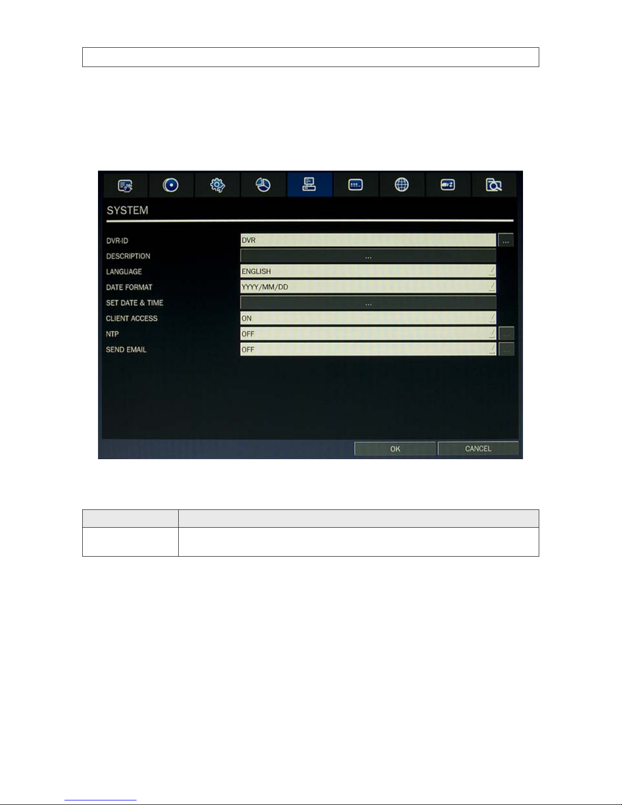
3.6 SYSTEM menu
Clicking the SYSTEM tab opens the system menu. Navigate through the menu items using mouse. You can also navigate the menus
with the p, q, t, and u buttons, and press SEL to select options.
Table 11. Menu Items in SYSTEM Setup Screen
Item Descript ion
DVR ID Selec t the submenu button to open the vir tual keyboard, then click your way to a ne w name for your DVR. The DVR ID c an
have a mos t 10 char acters.. Click OK when nished.
31H.264 DVR User Manual
SECTION 3: SYSTEM SETUP
Item Descript ion
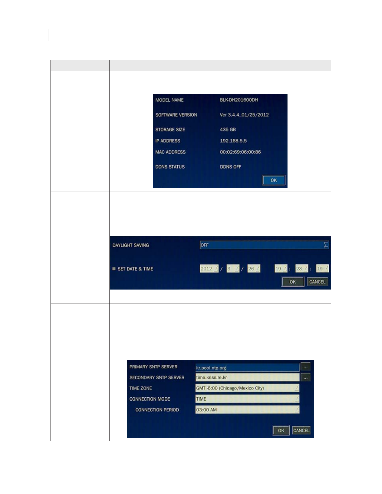
DESCRIPTION Click the DESCRIPTION submenu button to open an information showing a summary of your DVR. OPres s the SEL butto n to
view sy stem information (hardware version, soft ware version, s torage size, IP addres s, MAC address, an d DDNS status). NOTE :
This win dow shows the soft ware version number. Click OK to close the window.
LANGUAGE Open th e drop-down list to selec t your preferred menu system language. Se veral language options are available.
DATE FORMAT
Selec t the date format using the p, q, t, and u buttons. Options include: Y YYY/MM/DD, MM/D D/Y YYY, DD/MM/YYYY,
YYY Y-MM-DD, MM-DD-YY YY, DD- MM-YYYY.
SET DATE & TIME Click the submenu button to open the DATE & TIME setup win dow. Click each eld and sele ct the current value from the drop -
down lis t. In the DAYLIGHT SAVINGS list, s elect OFF, USA, EU (Euro pean union) or OTHER S. Click OK to commit the sett ings.
CLIENT ACCESS Enable (ON) or Disable (OFF ) remote access through network client soft ware.
NTP Click th e NTP eld and select ON, then click the submenu but ton to open the NTP setup menu. Us e this feature to s ynchronize
the clocks of computer sys tems over variable-latenc y data networks.
PRIMARY SNTP SERVER: Use the vir tual keyboard to enter the address of the primary NTP time s erver.
SECONDARY SNTP SERVER: Use the vir tual keyboard to enter the address of the secondar y NTP time server.
TIME ZONE: Select the oset from GMT (Greenwich Mean Time).
CONNECTON MODE: Select an NTP time server connection mode (INTERVAL/TIME).
INTERVAL: Synchronize the clock by hours shown on the connection period option.
TIME: Synchronize the clock at t he time daily show n on the connec tion period m enu. CONNECTI ON PERIOD: 1 ~ 24.
32
SECTION 3: SYSTEM SETUP
Item Descript ion
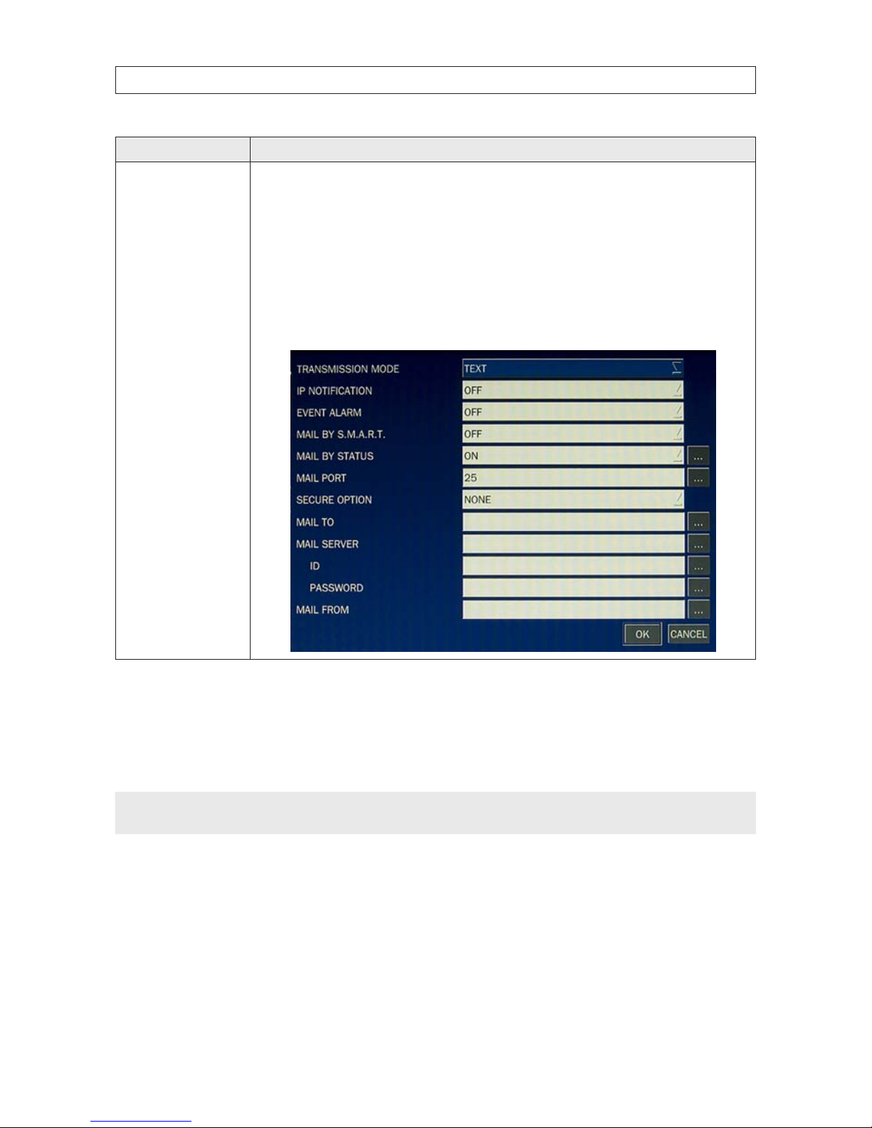
SEND EMAIL Click the SE ND MAIL eld and select ON, then click the submenu but ton to show the setup options .
TRANSMISSION MODE: When an alarm is triggere d, send an image of only the channel that triggered the alarm.
IP NOTIFIC ATION: Enable/disable sending email when the IP address of your DVR is chan ged.
EVENT AL ARM: When an alarm is triggered, enable/disable sending email repor ts of the channel that triggered t he alarm.
MAIL BY S.M.A.R.T.:
MAIL PORT: Port number of th e mail server.
SECURE OP TION: Select secu rity method: NONE, SSL or TL S
MAIL TO: Us e the virtual keybo ard to enter the email addre ss of the recipient.
MAIL SERVER: Use t he virtual keyboard to enter the mail s erver infor mation.
ID: Use the vir tual keyboard to spec ify the user ID for the mail server.
PASSWORD: Use the v irtual keyb oard to specify the connection password f or the mail ser ver.
MAIL FROM: Use the virt ual keyboard to specify the email addres s sent to the destination hos t.
3.7 SECURITY menu
Clicking the SECURITY tab opens the security menu. Navigate through the menu items using mouse. You can also navigate the
menus with the p, q, t, and u buttons, and press SEL to select options.
NOTE
You must be a user with Admin permissions to congure the SECURITY menu.

33H.264 DVR User Manual
SECTION 3: SYSTEM SETUP
Table 12. Menu Items in PASSWORD Setup Screen
Item Descript ion
USER AUTHENTIC ATION Click th e User Authentication submenu but ton to open the PASSWORD an d PERMISSION menu. Check or uncheck boxes to
allow per missions to dierent users for acce ss to areas of the system.
In the PASSWORD CHECK row, check or uncheck t he box to selec t for all users, o r check or uncheck the individual settings for
each user. Press ESC to ret urn to the SECURITY menu. Options are dene d as:
SETUP: Access to t he SETUP menus
PB: Control vide o Playback
PTZ: Co ntrol and congure PTZ (Pan/Tilt/Zoom) de vice settings
R/OFF: Control manual re cording (ON/OFF )
NETWORK: Change network set tings

34
SECTION 3: SYSTEM SETUP
Item Descript ion
USER PASSWORD Click the User Password submenu button to open the pa ssword setup menu. To change a password, sele ct a user from the
drop- down list, th en enter the current, new, and conr m password elds Clic k OK when nished. The f actory default Admin
user password is 1111.
PLAYBACK AUTHORIT Y Click the User Play back Authority submenu button to open the setup menu. Check or uncheck boxes to assign playback right s to
users for vie wing video clips of cameras channels .
NOTE
For improved system security, it is strongly recommended that you change the factory default passwords during the initial
setup of your system.
3.8 NETWORK menu
Clicking the NETWORK tab opens the setup menu. Navigate through the menu items using mouse. You can also navigate the menus
with the p, q, t, and u buttons, and press SEL to select options.
NOTE
You must be a user with Admin permissions to congure the NETWORK menu.
For additional guidelines for determining network settings, refer to the DVR Networking Guide provided with your system. This
guide is also available through your support team.

35H.264 DVR User Manual
SECTION 3: SYSTEM SETUP
Table 13. Menu Items in the NETWORK menu
Item De scription
PORT Click the subm enu button to open a keypad for entering the port number (default: 5445)
WEB PORT Click the submenu button to open a keypad for entering the web sever port number (def ault: 80)
NETWORK TYPE Select a t ype of network connection. O ptions are: DHCP or STATIC. NOTE: Depending o n the type selected, the options in the
network menu will change app ropriately.
DHCP If sele cted, the DVR automatically acquires its network settings from a DHCP server. This ad dress may change without not ice.
STATIC If sele cted, you mus t congure the ne twork set tings manually. These sett ings remain in e ect until manually changed.
IP: Enter the IP address assign ed to the DVR.
GATEWAY: Enter the Gateway IP address assigned for the DVR.
SUBNET MASK: E nter the Subnet Mask for the subnet where the DVR is conne cted.
DNS: Enter the DNS primar y and secondary server addres ses.

36
SECTION 3: SYSTEM SETUP
Item De scription
DDNS To use DDNS, open the drop-down list and selec t SERVER1, then click the submenu button to the right. S elect ddnscenter.com
from the thre e DDNS server s. (If you selec t another DDNS server, the DVR cannot connect to the DD NS properly.)
DDNS (SERVER1): Selec t one of the following DDNS ser vers: in USA, use w ww.ddnscenter.com, in Korea, use w ww.
okddn s.com, or if in the EU, or use w ww.bestddns.com.
DDNS INTERVAL: 5 - 60 minutes.
If you select SERVER 2 from the drop-down list, you can congure the DVR to use a general-purpose DDNS ser ver.
NETWORK STREAM Click the submenu button to open netwo rk stream setup submenu This menu is used to congure the res olution, frame rate,
and quali ty at which live video f rom each camer a can stream across the network . The total data rate permissible is dep endent
on the mo del of your DVR. Refer to the Spec ications sect ion for more information. C Set the preferred options using the dropdown lis ts, then sele ct OK.
3.8.1 Network ports
When you connect one or more DVRs to a network through an IP sharing device, each DVR must be assigned a unique TCP port
number for access from outside the LAN. Additionally, the IP sharing device must be congured to forward the assigned port to the
specic DVR.
NOTE
This port number is listed next to the Port menu option in the Network Setup screen. If you access the DVR only from within the
same LAN, the TCP port number does not need to be changed.

37H.264 DVR User Manual
Network access beyond a router
To access the DVR beyond a router (rewall), you must open TCP ports for commands, for live channels, and for storage channels.
The default DVR port numbers are 5445 and the web port number 80. If this port is not opened properly, you cannot access the DVR
outside a router.
3.9 CONFIG menu
Clicking the CONFIG tab opens the system conguration menu. Navigate through the menu items using mouse. You can also
navigate the menus with the p, q, t, and u buttons, and press SEL to select options.
Table 14. CONFIG menu items
Item Description
SAVE SETUP TO A USB Click th e submenu icon. To save the cur rent system co nguration to t he USB ash drive, plug the ash dri ve into the USB por t on
the front panel, click OK to conr m the operati on, then follow the on-screen prompts to complete the save. NOTE: If the message
“CHECK USB” appear s, repeat the process until “SAVE SUCCESS” is shown.
SECTION 3: SYSTEM SETUP

38
Item Description
LOAD SETUP FROM
A USB
Click th e submenu icon. To upload a saved DVR conguration from a USB ash drive, plug the ash drive into t he front panel USB
port, click OK to conrm the operat ion, then follow the on-screen prompts to complete the upload.
LOAD DEFAULT Click th e submenu icon. Selec t YES to load the system default settings. NOTE: The following items are not re set: language, DVR ID,
Security User Aut hentication, Securit y User P/W, date format, DLS sett ings, network set tings, HDD overwr ite, limit recording, HDD
serial number, and HDD ERROR time.
LOAD FACTORY
DEFAULT
Click th e submenu icon. Selec t YES to reset the sys tem to the factory d efault set tings.
SOFT WARE UP GRADE Click the submenu icon. Select SC AN to search the USB le for r mware, then follow the on-screen instructions to complete the
upload.
SECTION 3: SYSTEM SETUP

39H.264 DVR User Manual
SECTION 4
Live, Search, and Playback
In the Live screen, video inputs from the cameras are displayed the On-screen display (OSD) features as congured in the Display
Setup screen. OSD icons that indicate the status of the DVR are shown along the bottom of the screen.
Table 15. Status Indicator Icons in Live Viewing Screen
Icon Description
Power O. To power o the s ystem, click this icon t hen follow the on-screen instructions.
Lock/Unlock SETUP but ton.
Setup b utton. Click this bu tton to open the SETUP menu.
Audio button. Click this but ton to set the audio reception typ e: audio mute, single audio channel, or 4 audio channels. To set a sin gle
audio channel, r st select a speci c channel on the live screen.
Search button. Click this bu tton to open the search menu.
Backup but ton. Click this button to per form a backup.
PTZ but ton for control of PTZ camer as. When this button is clicke d, a PTZ control window will open.
SECTION 4: LIVE, SEARCH, AND PLAYBACK

40
SECTION 4: LIVE, SEARCH, AND PLAYBACK
Icon Description
Sequence but ton. Click this button to use a sequence fu nction.
Manual Re cord button. Click t his button to b egin recording.
Alarm- out function on/o button. When an alarm is in progress, click this but ton to stop reporting the alarm.
Click th e split screen icon to change the current split screen mode.
Indicates that the lock is set.
Indicates that alarm is set. To set the alar m function, press the Alarm but ton on the front panel.
Indicates that the alarm output is ac tivated.
Audio mute. To set audio mute, press the Audio button on the f ront panel.
Single audio channel. To set audio single channel for t he selecte d channel only, press the Audio but ton on the front panel.
To mix audio channels, press the Audio but ton on the lef t side.
Alarm indicator. When an alarm is ac tivated (sensor or motion alarm) in the v ideo channel, this icon will be highlighte d bright red.
Indicates that a net work client is connec ted to the DVR.
Indicates that sequencing mode is enabled.
The cur rent date and time.
Remote co ntrol ID display. If a remote ID is not set, the me ssage “A(all)” is displaye d.
Display s the amount of recording space used on the hard disk from 0-99%.
Indicates that HDD is re cycled (full and over writing oldest data with new data).
Continuous recordin g in progress.
Manual re cording in progress. To set Manual recording mo de, press the Re cord button on the front panel.
Motion alarm re cording in progress.
Sensor recording in progre ss.

41H.264 DVR User Manual
SECTION 4: LIVE, SEARCH, AND PLAYBACK
OSD menu
You can open the on-screen display menu with the mouse by right-clicking anywhere on the Live screen. Options in the OSD
menu are also represented by the icons in the tray at the bottom of the screen. See “Table 15. Status Indicator Icons in Live Viewing
Screen” on page 39 for a description of these icons.
4.1 SEARCH menu
To open the SEARCH menu, press the SEARCH button on the front panel or click the SEARCH icon on the Live screen.
Recorded data can be searched in the following ways: TIMELINE, EVENT, GO TO FIRST TIME, GO TO LAST TIME, GO TO SPECIFIC TIME,
ARCHIVE, and LOG.

42
SECTION 4: LIVE, SEARCH, AND PLAYBACK
4.1.1 TIME-LINE search
The TIME-LINE search window is used to nd stored video by using the time line bar. Select TIME LINE in the SEARCH menu, then
select NEXT. A calendar window will open.
The highlighted days in the calendar window indicate that data was recorded at that time. The day selected is highlighted blue.
Select the day of interest, then select NEXT.
Marker
In the TIME LINE window, the highlighted bars show the time of day when data was recorded. Drag the marker to the time when
you want to begin playing a recording, click the channel number of interest, then click NEXT to play the video. To expand the
timeline, click the icon in the upper-right corner between the t and u buttons. To stop the video playback, press the ESC button
on the front panel.

43H.264 DVR User Manual
SECTION 4: LIVE, SEARCH, AND PLAYBACK
4.1.2 EVENT search
Use EVENT search to quickly nd recordings associated with specic events. To open the EVENT search window, select EVENT on
the SEARCH window, then select NEXT. A calendar window will open (see above).
The highlighted days in the calendar window indicate that video was recorded at that time. Select the day of interest, then select
NEXT.
In the Event list window, click the event of interest, then click NEXT to play the video. Press the ESC button to stop playing the video
and return to the event list window.
The submenu button in the upper right corner opens a channel selection window where you can select the specic channel you
want to play. Select the channel, the press the ESC button to return to the event list window.
4.1.3 GO TO FIRST TIME search
You can access from the oldest recorded data on the DVR by selecting GO TO FIRST TIME on the SEARCH window. Press the ESC to
return to the SEARCH window.
4.1.4 GO TO LAST TIME search
You can access from the last minute recorded data on the DVR by selecting GO TO LAST TME on the SEARCH window. Press the ESC
to return to the SEARCH window.
4.1.5 GO TO SPECIFIC TIME search
In the SEARCH window, select GO TO SPECIFIC TIME, then use the mouse with the drop-down lists or the p, q, t, and u
buttons to enter the starting time of the video you want to play.

44
To stop playing video, press the front panel ESC button or click the T icon. If no video was recorded at the time you entered, a NO
DATA EXIST message will appear.
4.2 ARCHIVE search
Backed up data can be retrieved trough the Archive search and then backed up to portable media for use away from the DVR.
NOTE
Before you can search for an Archived video clip, clips must rst be backed up. See Backup video clip below.
To perform an Archive search (search of backed up recorded video or photo), select ARCHIVE in the SEARCH window. A calendar
window will open. The highlighted days in the calendar window indicate that data was backed up on those days. The data backed
up may be recorded (timestamped) on a dierent day. Select the day when the data was archived, then select NEXT.
SECTION 4: LIVE, SEARCH, AND PLAYBACK
45H.264 DVR User Manual
SECTION 4: LIVE, SEARCH, AND PLAYBACK
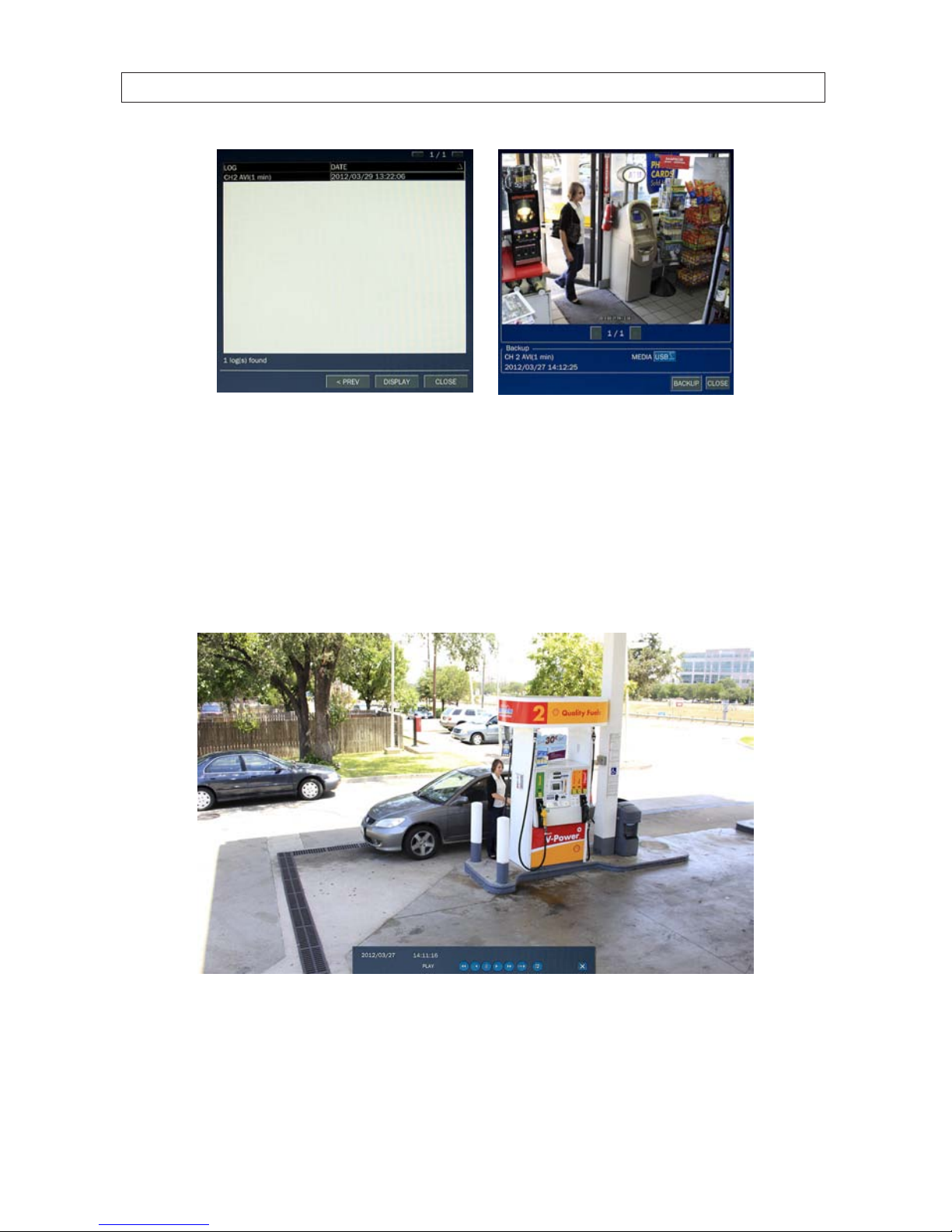
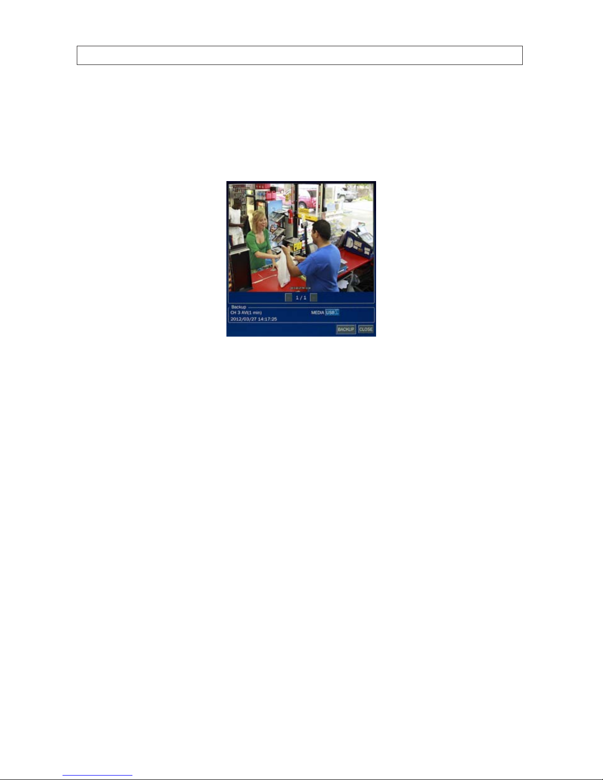
In the archive LOG list, select the le entry with the date and time when the data was backed up, then select DISPLAY. In the
ARCHIVE IMAGE window, the timestamp of the recorded is shown in the Backup frame. Select the image and MEDIA location, then
click BACKUP. To close the ARCHIVE IMAGE window, press ESC or click CLOSE.
4.3 PLAY mode
Playing a recorded event changes the DVR mode from SEARCH to PLAY. While in PLAY mode, you can return to the SEARCH screen
by pressing the front panel ESC button or clicking the
T icon.
Playback controls are located at the bottom of the screen.

46
SECTION 4: LIVE, SEARCH, AND PLAYBACK
Mode Backup Close
Timestamp
Play controls
Table 16. Playback controls (PLAY Mode)
Icon Des cription
Go to the previous menu screen or searc h window, or exit f rom the menu.
t t
Selec t to rewind the recording. Select again to in crease the rew ind speed.
-- t
Jump/step back ward. The playb ack position moves 6 0 seconds back.
u / II
Selec t to play or pause a recording.
u --
Jump/step for ward. Playback posit ion moves 60 se conds ahead.
u u
Selec t to fast for ward the recording. Selec t again to increa se the fast forward speed.
-- u-
Slow playback.
Selec t to backup video clip..
4.4 Backup video clip
You can archive the video clip by clicking the Backup button in Play mode (see the screen above. The system adds all backed-up
video clips to the Archive search list. The Backup button is located on the play control bar.
Timestamp marker Backup button
Play motion controls Close Play mode button
To archive the clip:
1. Click the Backup button.
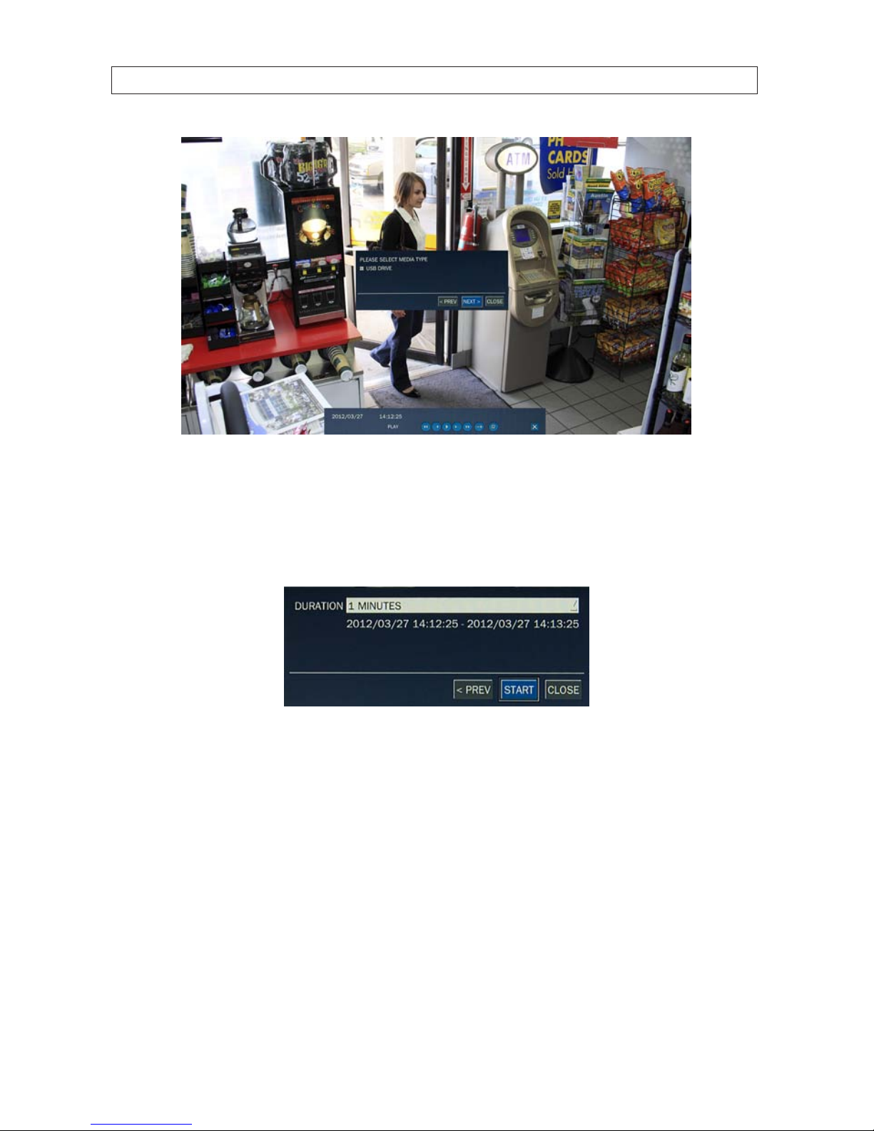
47H.264 DVR User Manual
SECTION 4: LIVE, SEARCH, AND PLAYBACK
2. Select the device you want to backup (archive) to. All archive devices are listed in the media window.
3. Click NEXT.
4. In the window that opens, select the duration of the video clip from the drop-down list, then click START.
Allow the backup operation to complete before continuing.

48
SECTION 5: PTZ CONTROL
SECTION 5
PTZ Control
To control the PTZ functions of the camera, select Camera PTZ on the OSD menu. Use the p, q, t, and u buttons to select the
channel of the PTZ camera and features you want to control.
Table 17. Button functions in PTZ control
Item Desc ription
INITIALIZE Initialize the PTZ se ttings of the selec ted camera.
PAN / TILT
Selec t PAN/ TILT using the p q t and u bu tton, then and press SEL. Adjust the tilt (UP/
DOWN)/pan (LEFT/RIGHT) position using the p, q, t, and u buttons.
ZOOM / FOCUS
Selec t ZOOM/FOCUS using the p, q, t, and u buttons, then press SEL. Adjust t he zoom
(UP/DOWN)/fo cus (LEFT/RIGH T) position using the p, q, t, an d u buttons.
OSD
Selec t OSD to enter the menu. Cont rol keys are Right, Lef t, UP, Down, Select, Far (REW K EY),
and Near (F F KEY). Press th e ESC button to retur n to the previou s menu. Press the PTZ bu tton
to close the OSD menu.
AUTOSCAN
Press t he right key (u) to star t auto scan. Pre ss the left ke y (t) to stop au to scan.
PRESE T
Selec t PRESET, then press th e left key (t). A number input wind ow will appear. Set the
number (3 digits) using th e number key, then pre ss the SEL to conr m the preset number for
the cur rent position. Pres s the right key (u) and enter the number (3 digi ts) to go to the preset
posit ion.
TOUR
Selec t TOUR and press t he right (u) key. A number inpu t window will open. Sele ct a number
(1 digit) using a number key, then press SEL to start the tour. Press the le ft (t) key to stop the
tour. Pres et the number of t he tour group in the OSD menu.
NUMBER For the TOUR and PRESE T menu.
Press ESC to return to t he main menu.
The Preset, Tour, OSD, and Autoscan function are only available on some camera models.

49H.264 DVR User Manual
SECTION 6 : BACKUP
SECTION 6
Backup
Still images and video clips can be backed up in both Live mode and Playback mode, and written to a USB ash drive (with FAT32
format) or CD/DVD. A CODEC installer (CODEC required for playing AVI les with Windows Media Player) is also written to the
backup device.
6.1 Still image BACKUP onto USB ash drive
Still images can be captured and backed up onto the USB ash drive or CD/DVD while in Live mode or during video playback. To
initiate a backup, press the BACKUP button or select the BACK UP menu to launch the backup (archive) function.
1. If in Live mode, select the channel to backup the image from. The BACKUP window will open.
2. Select the media you want to save the image on. If you want to backup the image to a USB ash drive, insert the drive into
the USB port on the back or front of the DVR. If you want to backup to a CD or DVD, place a blank CD-R/W or DVD-R/W disk
into the DVD drive. If no DVD-RW drive is installed in the DVR, the only backup option is USB.
3. Click START. When the backup is complete, a message will appear. When the DVR backs up to a USB ash drive, it will create
a directory on the ash drive with a date-coded named in the format “YYYYMMDD” (ex. “20110210”) and write the le
there.
6.2 Video BACKUP
Recorded video can be backed up onto the USB ash drive or CD/DVD-RW drive in playback mode. To perform the backup:
1. In playback mode, press the BACKUP button to launch the archiving function.
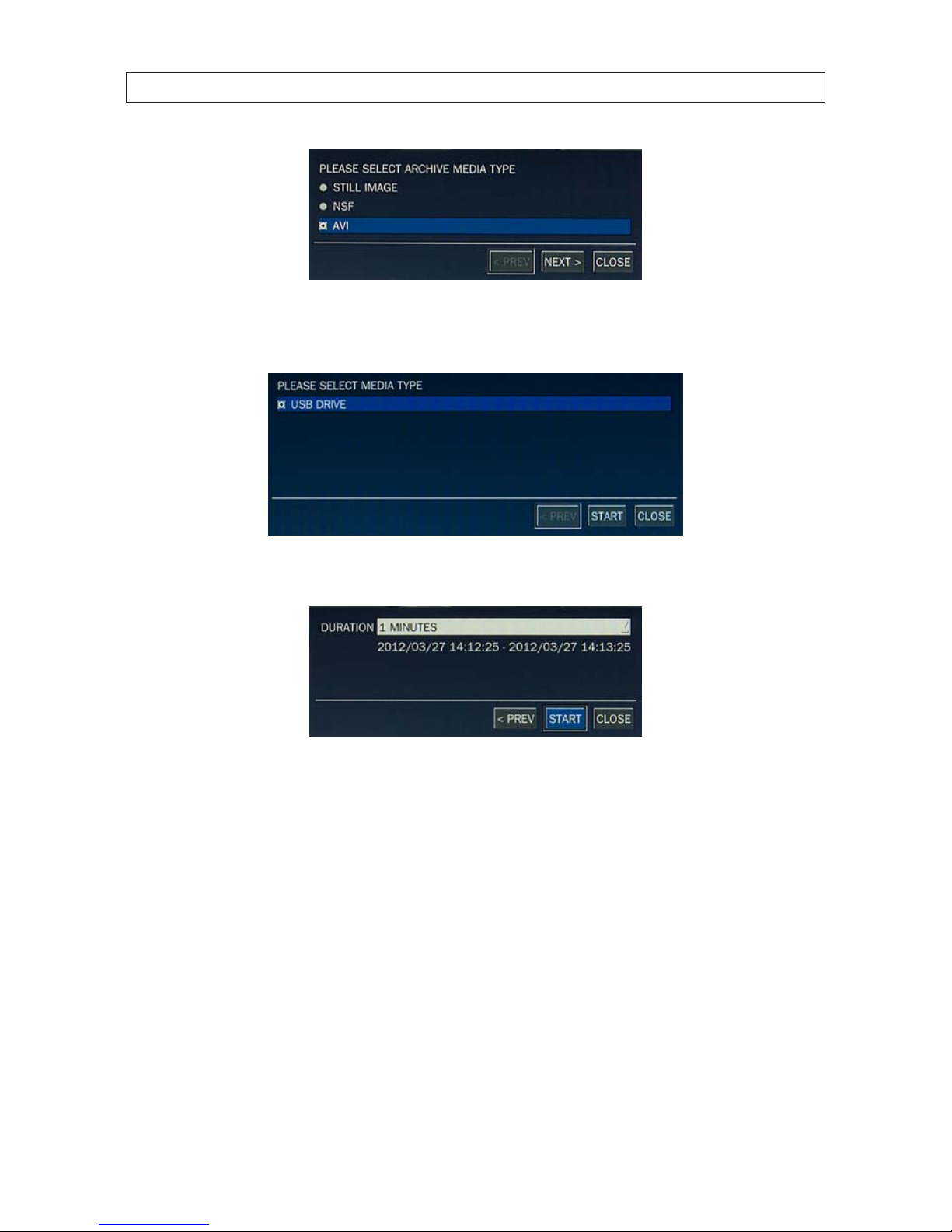
2. When the BACKUP window opens, select STILL IMAGE, NSF (native video format), or AVI (video format), then select Next.
50
SECTION 6 : BACKUP
3. In the media window, select the media type you want to backup to. If no DVD-RW drive is installed in the DVR, the only
backup option is USB.
4. In the BACKUP window, select the channels to backup (if shown), the duration (from the drop-down list), then select Start.
5. Select START. When the backup is complete, a message will appear. When the DVR backs up to a USB ash drive, it will
create a directory on the ash drive with a date-coded name in the format “YYYYMMDD” (ex. “20120327”) and write the le
there.
6.3 BACKUP still images or video from the ARCHIVE list
Video clips and images stored in the ARCHIVE list on your hard drive can be copied to a USB ash drive or a CD/DVD. To perform the
copy:
1. Use the mouse or the p, q, t, u, and SEL buttons to open the SEARCH window and select ARCHIVE. A calendar window
will open. Dates highlighted in the calendar window indicate that archived data exists for those days.
2. In the calendar window, select a date, then select Next.
51H.264 DVR User Manual
SECTION 6 : BACKUP
3. Scroll through the archive list and highlight the le of interest. Select DISPLAY.
4. In the ARCHIVE IMAGED window, select the media (USB or CD/DVD-R). If you want to copy the le to a USB ash drive, insert
the drive into the USB port on the back or front of the DVR. If you want to backup to a CD or DVD, place a CD-R/W or DVDR/W disk into the DVD drive.
5. Select BACKUP to copy the le to the media drive.
6. When the backup is complete, select CLOSE button to return to the LOG list window.
6.4 Playing backed up video clips
Video clips are backed up from the DVR in AVI or NSF format. AVI les can be played in Microsoft® Windows® with Window Media®
Player and other players compatible with AVI formatted les. A CODEC installer, written to the backup device with the AVI le,
should be executed before playing AVI les with Media Player.

52
SECTION 7: REMOTE CLIENT SOFTWARE
SECTION 7
Remote Client Software
Remote Client software is used to remotely monitor a single DVR. It can be used to display live images from your cameras, search for
and play back recorded data, monitor alarms, control PTZ devices, and capture and backup data.
NOTE
In a high bandwidth network, a maximum of four users can access one DVR simultaneously. In a low bandwidth network it is
recommended that only one user access the DVR at a time.
7.1 PC Requirements
For the Remote Client software, the minimum PC requirements are:
• CPU: Intel® Pentium® IV, 1.4 GHz or higher
• Memory: 512MB (1GB or larger is recommended.)
• VGA memory: 16 MB (64 MB or larger is recommended.)
• Resolution: 1024 x 768
• Supported operating systems: Microsoft® Windows® 2000, Windows XP Professional, Windows XP Home, Windows 7
• DirectX®: DirectX 8.1 or higher
7.2 Installing the Remote Client
1. Insert the provided CD in the CD drive. Open a le list of the CD, then double-click “RemoteClient(xxxxxx).exe” to install the
le.
CD Contents (typical)
2. Browse for the preferred destination location in the InstallSheild Wizard window, then click “Next”.

53H.264 DVR User Manual
SECTION 7: REMOTE CLIENT SOFTWARE
3. Select the preferred program folder, then click “Next”. The setup status screen will open.
4. Select a Program Folder, then click Next. The Remote Client will be installed and a Remote Client icon will appear on the
desktop.
5. Close the InstallShield window.
7.3 Remote Client initial display
To open the Remote Client, double-click the icon on the desktop, or open it through the Windows Start menu.

54
SECTION 7: REMOTE CLIENT SOFTWARE
Table 18. Remote Client window components
Button Function Descr iption
WINDOW CONTROL
Buttons for expanding t he image to full screen (press ESC to re turn to
normal viewing), minimizing the window, expan ding window to full
screen, and closing the window.
DATE & TIME Display s the current date and time.
CONNEC T/DISCONNEC T Connec t/disconnect a DVR .
SEARCH/LIVE Switches fro m Live mode to Search mode.
KEYPAD
Selec t a channel. Click the channel button, or doub le-click the channel on
the Live view sc reen.
SPLIT-SCREEN MODE Selec t a split-screen mode 4 -, 9-, or 16-channel display.,
PAN/TILT - /ZO OM/
FOCUS
Control the PAN/TILT and ZOOM/FOC US features on the remote camer a. To
swir tch between the PT an d ZF dials, click the but ton in the center.

55H.264 DVR User Manual
SECTION 7: REMOTE CLIENT SOFTWARE
Button Function Descr iption
PTZ camera funct ions:
Scan, Tour, Menu
Controls
These icons invoke Scan, Tour and Menu Controls set up in a PTZ camera.
FUNCTIONS
CAPTURE: Capture a still image of the s creen.
PLAY/PAUSE: Play/freeze live video
BACKUP: Initiate backup oper ation (record on/o).
PRESET: Select c amera position pre set.
SETUP: Open th e setup menus.
ALARM: The ON/O FF button of the alarm o utput of the DVR . When an
alarm is active, this button is red.
HDD USAGE DVR HDD space use d Indicator.
NETWORK BANDWIDTH Shows the tran sferred frames and net work bandwidth.
AUDIO Adjust the volume. Click the (speaker) icon on the le ft to mute the volume.
LOG WINDOW
7.4 Setup
The Remote Client includes several setup options, including presets for the DVRs you want to connect to. To open the setup menus,
click the Setup button.
7.4.1 General Setup
When the Setup menu is opened, the General options are displayed.

56
SECTION 7: REMOTE CLIENT SOFTWARE
General options include:
• Security Option: Set a password for security options. If set, you must enter the password when accessing any of the security
functions.
• Save Path: Specify the location backup and still image captures are saved.
• Automatic Reconnection: If a user selects this function, the client will automatically try to connect to the previously
connected IP address if the network connection is lost.
• Time Format: Select the format for displaying the time.
After entering all elds in the Site Additions window, click OK to save your entries and exit the Setup menus.
7.4.2 Site Setup
To open the Site menu, click the Site entry in the left frame of the Setup window.
Initially, no site (DVR) is listed. To add a site, click the Addition button.

57H.264 DVR User Manual
SECTION 7: REMOTE CLIENT SOFTWARE
In the Site Addition menu, enter:
• Site Name: Enter an appropriate name for the DVR you will connect to.
• IP Address: Enter the IP address and web port number (if other than 80).
• Port No: Enter the port number for the DVR. The default DVR port number is 5445.
• ID: Enter your login ID (login name).
• PASSWORD: Enter the password associated with the login ID. The default login ID and password are Admin and 1111.
• Channels: Enter the number of channels supported by your DVR (4, 8, or 16).
After entering all elds in the Site Additions menu, click OK to save your entries and exit the Setup menus.
7.4.3 Event Setup
To open the Event menu, click the Event entry in the left frame of the Setup window. The Event menu allows you to congure how
the client will display and log event information received from the DVR.

58
SECTION 7: REMOTE CLIENT SOFTWARE
In the Event Setup menu, set the following:
• Log Path: Click the browse button to identify where event log les are saved.
• Log Size: Set the maximum size in megabytes of the event log le space.
• Event Log: For each event type, select the checkbox to save the event data in the log le.
• Event Icon: For each event type, select the checkbox to display the event on live video.
• Event List: For each event type, select the checkbox to show the event in the Event List in live mode.
After entering all elds in the Site Additions menu, click OK to save your entries and exit the Setup menus.
7.4.4 Event Search Setup
The Event Search window is used to display a list of the logged events that occurred during a specied time period. Use the
dropdown lists to choose the From and To times, then browse to the location of the log le. To save the list of events to another le,
click Save. An event timestamp can be used to easily nd the video recordings of the event.

59H.264 DVR User Manual
SECTION 7: REMOTE CLIENT SOFTWARE
After entering all elds in the Event Search menu, click OK to save your entries and exit the Setup menus.
7.4.5 Record Setup
To open the Record menu, click the Record entry in the left frame of the Setup window. The Record menu allows you to congure
the conditions that trigger live video recording.
In the Record menu, set the following:
• Record Condition: Select Always or Event, then Auto record.
• Event: If Event was selected as the Record Condition, select the type of event and the duration of the recording.
• Channels: Select the channels to be recorded during the conditions selected above.
After entering all elds in the Record menu, click OK to save your entries and exit the Setup menus.
7.4.6 Record Disk Setup
To open the Record Disk menu, click the Disk entry in the left frame of the Setup window. Use the Disk menu to select the location
where recorded data is saved, and the amount of space on the disk to allocate for recordings.

60
SECTION 7: REMOTE CLIENT SOFTWARE
In the Disk menu, select the storage drive from the dropdown list, then enter the size of the storage buer in megabytes. Choose
either Replace oldest les or Stop recording when the disk is full. Click OK to save your entries and exit the Setup menus.
7.4.7 Display Setup
Use the Display Setup menu in multi-monitor systems to correct the image on a secondary monitor. Use of this feature may degrade
the performance of the DVR.
7.4.8 Language Setup
To open the Language menu, click the Language entry in the left frame of the Setup window. Choose the preferred on-screen
language from the dropdown list, then click OK to save the selection and close the Setup menu.
7.5 Connecting to a DVR
To connect to a DVR, click the Connect button. The Connect dialog window will open. The Connect window is lled by the entry
made in the Setup Site menu.

61H.264 DVR User Manual
SECTION 7: REMOTE CLIENT SOFTWARE
In the Connect window, use the dropdown lists to select the DVR you want to connect to, then click OK. A Live view window from
your DVR will be displayed.
7.5.1 Bidirectional Audio
The Remote Client supports bidirectional audio between the client PC and a DVR. To use bidirectional audio, the client PC must have
a microphone and speakers. At the DVR, connect a microphone to the audio-in connectors, and a pair of amplied speakers to the
audio-out connectors.

62
SECTION 7: REMOTE CLIENT SOFTWARE
7.6 Remote Search mode and functions
After connecting to the DVR, the Remote Client can be used to search for and playback recorded video. Video clips can then be
backed up to a USB drive or local hard disk. To open the Search screen, click the Search button.
Table 19. Remote Client Search window components
Button Function Descr iption
WINDOW CONTROL
Buttons for expanding t he image to full screen (press ESC to re turn to
normal viewing), minimizing the window, expan ding window to full
screen, and closing the window.
DATE & TIME Display s the current date and time.
CONNEC T/DISCONNEC T Connec t/disconnect network connection.
LIVE/SEARCH Switches fro m search mode to live mode.
KEYPAD
Selec t a channel. Click the channel button, or doub le-click the channel
on the live view screen. NOTE: The number of channel but tons shown
indicates the capac ity of the DVR.
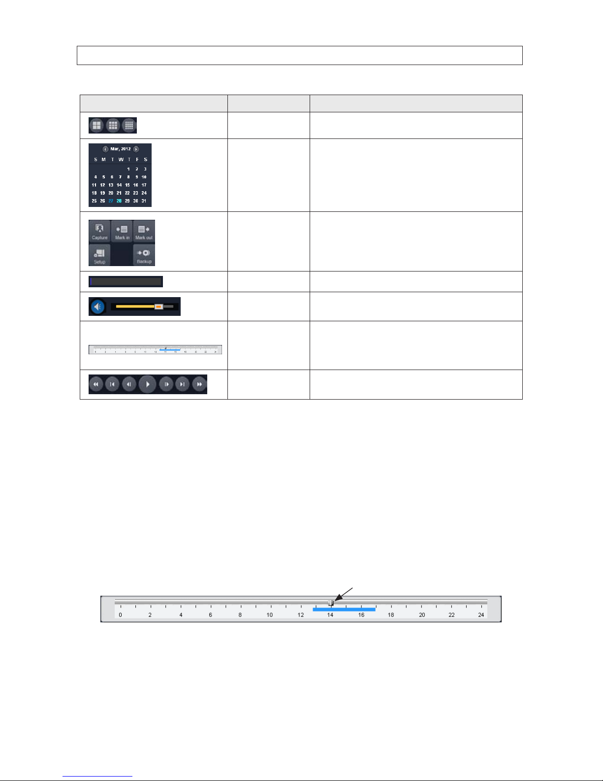
63H.264 DVR User Manual
SECTION 7: REMOTE CLIENT SOFTWARE
Button Function Descr iption
SPLIT-SCREEN MODE Selec t a split-screen mode 4 -, 9-, or 16-channel display.,
CALENDAR
In the calendar f rame, dates wi th recorded video are colored in light blue.
Click th e date of the recorded video you w ant to nd or play.
FUNCTIONS
CAPTURE: Capture a still image of the s creen/camera.
MARK IN: Set the s tart time at the marker position
MARK OUT: Set the end t ime at the marker position
SETUP: Display t he setup scre en of the network viewer.
BACKUP: B ackup the video clip f rom MARK IN time to MARK OUT time
HDD USAGE DVR HDD space use d Indicator.
AUDIO Adjust the volume. The audio is on o r muted by clicking the speaker icon.
TIMELINE Bar
Display s a timeline for the date selec ted in the calendar fr ame. Time spans
when video is re corded are marked in blue. To expand the display for an
hour when vide o was recorded, drag th e marker to the hour you want to
expand, then click the 0 - 60 but ton (locate d below the time line).
PLAYBACK BUTTONS
Use the playbac k buttons to control v ideo playback. The playbac k buttons
are labeled wit h the standard icons us ed for video play control.
7.6.1 Searching for and playing video recorded by the DVR
1. At the Remote Client, connect to the DVR.
2. Press the SEARCH button. The client will change from live mode to search mode.
3. In the calendar frame, click the date when video was recorded.
4. Drag the marker on the timeline to the time at which you want to play recorded video. To expand the hour within which the
marker lies, click the 0 - 60 button below the time line.
Marker
5. Click the PLAY button to begin playing video at the marker position.

64
SECTION 7: REMOTE CLIENT SOFTWARE
7.6.2 Backing up video from the DVR on the Remote Client PC
Video recorded in the DVR can be backed up on the PC where the Remote Client is installed. Video clips are saved in AVI format.
1. At the Remote Client, connect to the DVR.
2. Click the SEARCH button. The client will change from live mode to search mode.
3. In the calendar frame, click the date when the video was recorded.
4. Drag the marker on the timeline to the time at which you want to play recorded video.
Marker
To expand the hour within which the marker lies, click the 0 - 60 button below the time line.
5. Play the video to determine the time where you want to start backing up a clip, then pause the playback and click the MARK
IN button.
6. Continue playing the video to determine the time where you want to end the clip, then stop the playback and click the
MARK OUT button. The time span between the MARK IN and MARK OUT times will be highlighted in dark green.
Mark In Mark Out
7. Click the PLAY button to view the video clip you marked.

65H.264 DVR User Manual
SECTION 7: REMOTE CLIENT SOFTWARE
8. To backup the video clip you marked, stop the video playback, then press the BACKUP button. The Backup menu window
will open.
9. In the Backup menu, select the options you want, then click OK.
10. A pop-up window will appear when the backup operation is complete. Click OK to close the backup operation.
NOTE
Video backup can take several minutes to complete, depending on the number of channels selected and the duration of the clip.

66
SECTION 7: REMOTE CLIENT SOFTWARE
7.6.3 Image capture
A still image of a screen can be captured in either Live mode or Search mode, then saved as a BMP or JPEG le. To capture a still
image of the screen, click the Capture button. A Capture menu will open.
In the Capture menu, select the options you want, then click OK. An image of the screen will be saved at the location you specied.
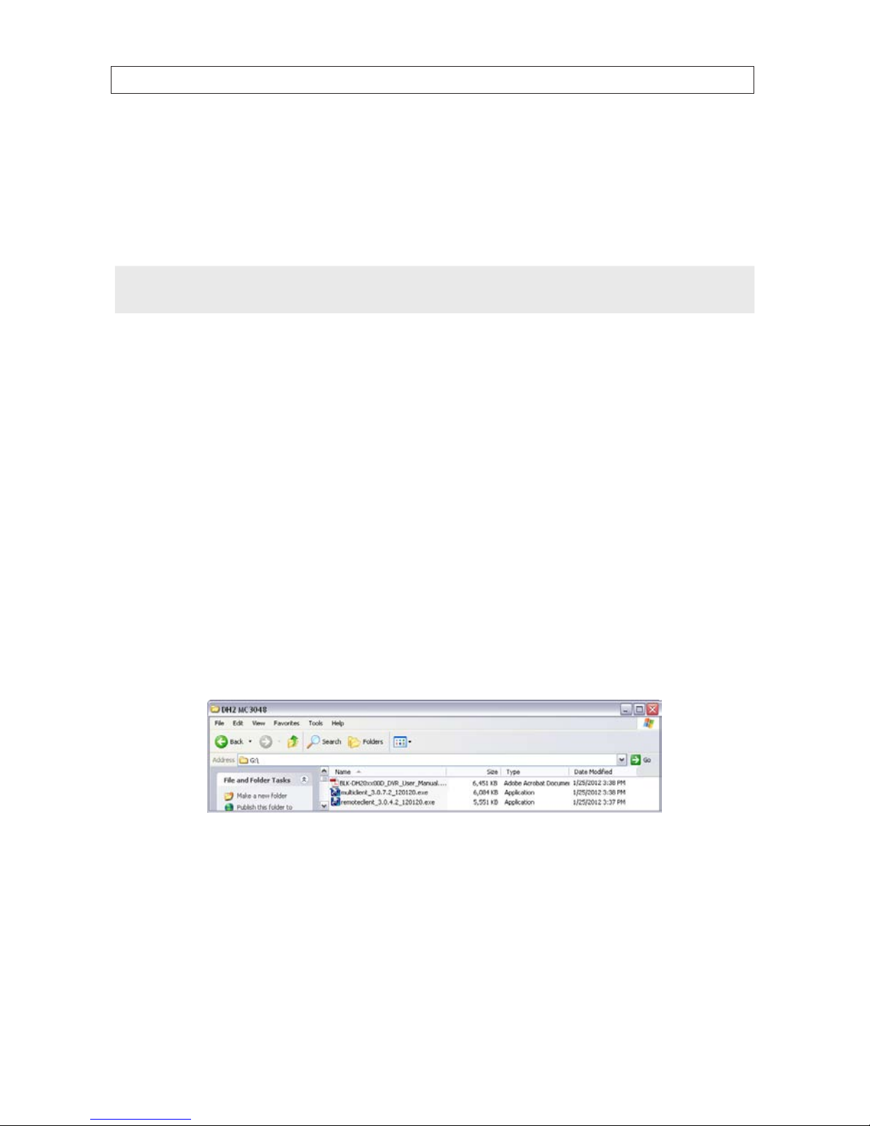
67H.264 DVR User Manual
SECTION 8: MULTI CLIENT SOFTWARE
SECTION 8
Multi Client Software
Multi Client software can monitor several DVRs (sites) simultaneously. It can display to up 256 live video channels on one screen,
playback video clips, control PTZ cameras, monitor alarms, and be congured with 2-way audio communication through the DVR.
NOTE
In a high bandwidth network, a maximum of four users can access one DVR simultaneously. In a low bandwidth network it is
recommended that only one user access the DVR at a time.
8.1 PC Requirements
For the Multi Client software, the minimum PC requirements are:
• CPU: Intel® Pentium® IV, 2GHz or faster
• Memory: 512MB (1GB or larger is recommended.)
• VGA memory: 16MB (64MB or larger is recommended.)
• Resolution: 1024 x 768
• Disk space: 1GB
• Supported operating systems: Microsoft® Windows® 2000, Windows XP Professional, Windows XP Home, Windows 7
• Network: 10/100BASE-T network
• DirectX: DirectX 8.1 or higher
8.2 Installing the Multi Client
1. Insert the provided CD in the CD drive. Open a le list of the CD, then double-click “MultiClient(xxxxxx).exe” to install the le.
CD Contents (typical)
2. Browse for the preferred destination location in the InstallSheild Wizard window, then click “Next”.

68
SECTION 8: MULTI CLIENT SOFTWARE
3. Select the program folder and click “Next”. The setup status screen is displayed.
4. Select a Program Folder for the Start menu, then click Next. The Multi Client will be installed and a “Multi Client” icon will
be displayed on the desktop.
5. Close the InstallShield window.
8.3 Multi Client initial display
To open the Multi Client, double click the icon on the desktop or open it through the Windows Start menu.

69H.264 DVR User Manual
SECTION 8: MULTI CLIENT SOFTWARE
Table 20. Multi Client screen components
Button Function Descr iption
WINDOW CONTROL
Buttons for expanding t he image to full screen (press ESC to re turn to normal
viewing), minimizing the window, expanding window to f ull screen, and closing
the window.
LOCAL PL AYBACK Search for video les record ed on the local P C.
REMOTE PLAYBACK Search for v ideo les recorded o n the DVR.
SITE CONT ROLS: Refresh,
Site Addition, Site Delete,
Net Finder
Icons in the upper-right corner of the screen. Applies control to sites selected in the
site lis t below. These icons link to: re fresh thumbnail, site addit ion, site delete, net
nder (si te modify)
SITE LIS T
List of sites ad ded to the DVR. The site list appears in the pane b eneath the site
contro ls icons.
CONNEC T Click to connect to sites selected in the frame above.
DISCONNECT Click to disconnect to sites selected in the frame ab ove.
SETUP Open the setup menus
CAPTURE Capture a still image of t he screen.
EVENT LIST Opens the list of events lo gged by the Mult i Client.

70
SECTION 8: MULTI CLIENT SOFTWARE
Button Function Descr iption
PAUSE Freezes the screen
ALARM
RECORD Enable/disable recordin g of live video.
SPEAKER, MICROPHO NE Controls for adjusting the volume of t he speaker and micropho ne.
PTZ camera funct ions:
Camera Preset, Scan,
Tour, Menu Controls
These icons invoke Preset, Scan, Tour and Menu Controls setup in the PTZ c amera.
PAN/TILT - /ZO OM/
FOCUS
Control the PAN/TILT and ZOOM/FOC US features on the remote camer a. To swi tch
between th e PT and ZF dials, clic k the button in the center.
CHANNEL SPLIT Use to selec t the number of channels (1/4/9/16) shown on the sc reen.
SITE SPLIT Use to select the numb er of DVRs (1/4/9/16) shown on the sc reen.
8.3.1 Using Net Finder
The Net Finder feature discovers BLK-DH20xx DVRs on the subnet, and can be used to quickly add it to Multi Client. To use Net
Finder:
1. Click the Net Finder icon in the upper left corner of the window.
Net Finder
2. In the Net Finder window, click the Find button to list the BLK-DH20xx DVRs on your network. Net Finder will list the DVRs
added to Multi Client in the left frame, and DVRs discovered on the network in the right frame.

71H.264 DVR User Manual
SECTION 8: MULTI CLIENT SOFTWARE
3. In the Net Finder right pane, click the DVR you want to add, then click the Add button.
In the Site Addition window, add a Site Name and an administrative ID and Password. In the screen above, the site name
entered is Desk.
4. Click OK to save your settings. The site you added will appear in the left frame of the Net Finder window, and the site list
frame on the left side of the Multi Client window.
8.3.2 Event List
Clicking the Event List icon opens the Event List window for the current Multi Client session.

72
SECTION 8: MULTI CLIENT SOFTWARE
8.4 Setup
The Multi Client includes several setup options. To open the setup menus, click the Setup button.
8.4.1 General Setup
When the Setup menu is opened, the General options are displayed.
General options include:
• Security Option: Set a password for security options. If set, you must enter the password when accessing selected security
functions.
• Save Path: Specify the location backup and still image captures are saved.
• Automatic Reconnection: If a user selects this function, the client will automatically try to reconnect to the previously
connected IP address if the network connection is lost.
• Time Format: Select the format for displaying the time.
After entering all elds in the Site Additions window, click OK to save your entries and exit the Setup menus.
8.4.2 Event Setup
To open the Event menu, click the Event entry in the left frame of the Setup window. The Event menu allows you to congure how
the client will display and log event information received from the DVR.

73H.264 DVR User Manual
SECTION 8: MULTI CLIENT SOFTWARE
In the Event Setup menu, set the following:
• Log Path: Click the browse button to identify where event log les are saved.
• Log Size: Set the maximum size in megabytes of the event log le space.
• Event Log: For each event type, select the checkbox to save the event data in the log le.
• Event List: For each event type, select the checkbox to show the event in the Event List in live mode.
After entering all elds in the Site Additions menu, click OK to save your entries and exit the Setup menus.
8.4.3 Event Search Setup
The Event Search window is used to display a list of the logged events that occurred during a specied time period. Use the
drop-down lists to choose the From and To times, then browse to the location of the log le. Click Find. To save the list of events to
another le, click Save. An event timestamp can be used to easily nd the video recordings of the event.

74
SECTION 8: MULTI CLIENT SOFTWARE
After entering all elds in the Event Search menu, click OK to save your entries and exit the Setup menus.
8.4.4 Record Setup
To open the Record menu, click the Record entry in the left frame of the Setup window. The Record menu allows you to select the
conditions with which live video from the cameras is recorded.
In the Record menu, set the following:
• Record Condition: Select Always or Event, then Auto record.
• Event: If Event was selected as the Record Condition, select the type of event and the duration of the recording.
• Channels: Select the channels to be recorded during the conditions selected above.

75H.264 DVR User Manual
SECTION 8: MULTI CLIENT SOFTWARE
After entering all elds in the Record menu, click OK to save your entries and exit the Setup menus.
8.4.5 Record Disk Setup
To open the Record Disk menu, click the Disk entry in the left frame of the Setup window. The Disk menu allows you to select the
location where recorded data is saved, and the amount of space on the disk to allocate for recordings.
In the Disk menu, select the storage drive from the dropdown list, then enter the size of the storage buer in megabytes. Choose
either Replace oldest les or Stop recording when the disk is full. Click OK to save your entries and exit the Setup menus.
8.4.6 Display Setup
To open the Display menu, click the Display entry in the left frame of the Setup window. The Display menu allows you to select
the kinds of information and events messages that appear on the scree. Each site you connect to can be congured dierently.
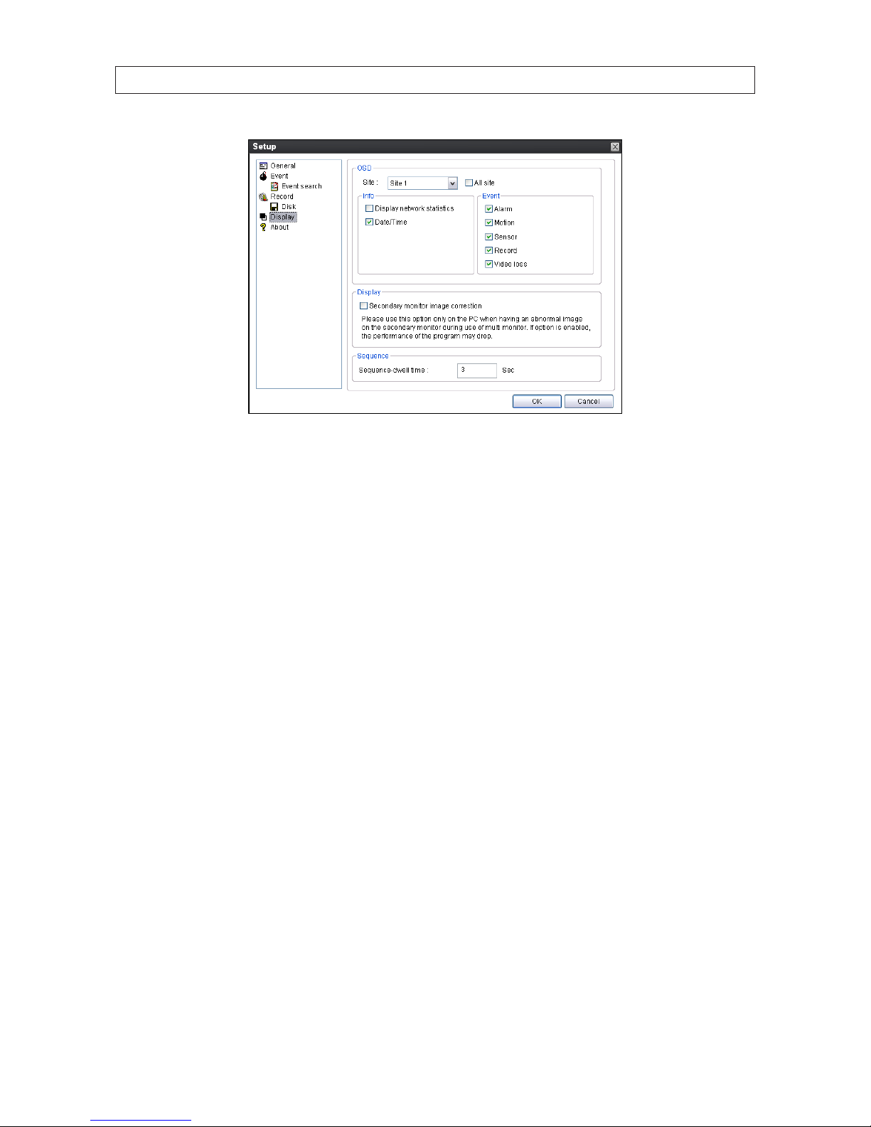
76
SECTION 8: MULTI CLIENT SOFTWARE
After selecting the preferred options in the Display menu for each site, click OK to save your entries and exit the Setup menus.
8.4.7 About Setup
The About Setup screen displays the version level of the Multi Client Software. The abbreviated copyright statement is also shown.
8.5 Connecting to a DVR
To connect to a DVR for the rst time:
1. Click the Site Addition button. The Site Addition dialog window will open.

77H.264 DVR User Manual
SECTION 8: MULTI CLIENT SOFTWARE
Site
Addition
button
2. In the Site Addition menu, enter:
— Site Name: Enter an appropriate name for the DVR you will connect to.
— IP Address: Enter the IP address and web port number (if other than 80).
— Port No: Enter the port number for the DVR. The default DVR port number is 5445.
— ID: Enter your login ID (login name). The default administrator ID is Admin.
— PASSWORD: Enter the password associated with the login name. The default administrator password is 1111.
3. After entering all elds in the Site Additions menu (see above) click OK to save your entries. An entry for the DVR you
added will appear in the site list frame (below the Site Addition icon).
4. Click the checkbox in the entry you added to the site list.
Select
Checkbox
5. Click the Connect button to connect to the DVR.
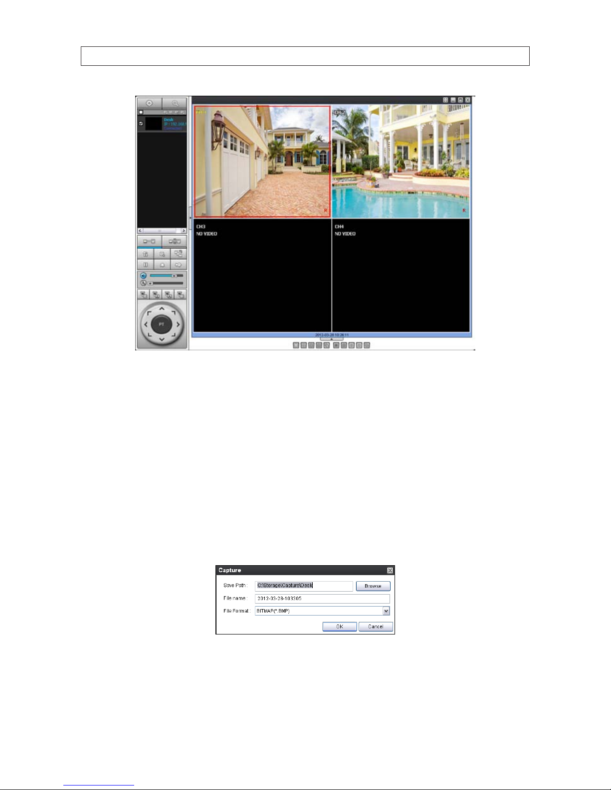
78
SECTION 8: MULTI CLIENT SOFTWARE
Multi Client DVR Live View
8.5.1 Bidirectional Audio
The Multi Client supports bidirectional audio between the client PC and a DVR. To use bidirectional audio, the client PC requires
connections for a microphone and speakers. At the DVR, connect a microphone to the audio-in connectors, and a pair of amplied
speakers to the audio-out connectors.
8.5.2 Capture
A still-image of a screen can be captured in either Live mode or Search mode and saved as a BMP or JPEG le. To capture a still
image of the screen, click the Capture button. A Capture menu will open.
In the Capture menu, select the options you want, then click OK. An image of the screen will be saved at the location you
specied. By default, captured images are saved in the directory specied in the Setup / General menu. However, the Save Path
can be changed in the Capture menu if necessary.
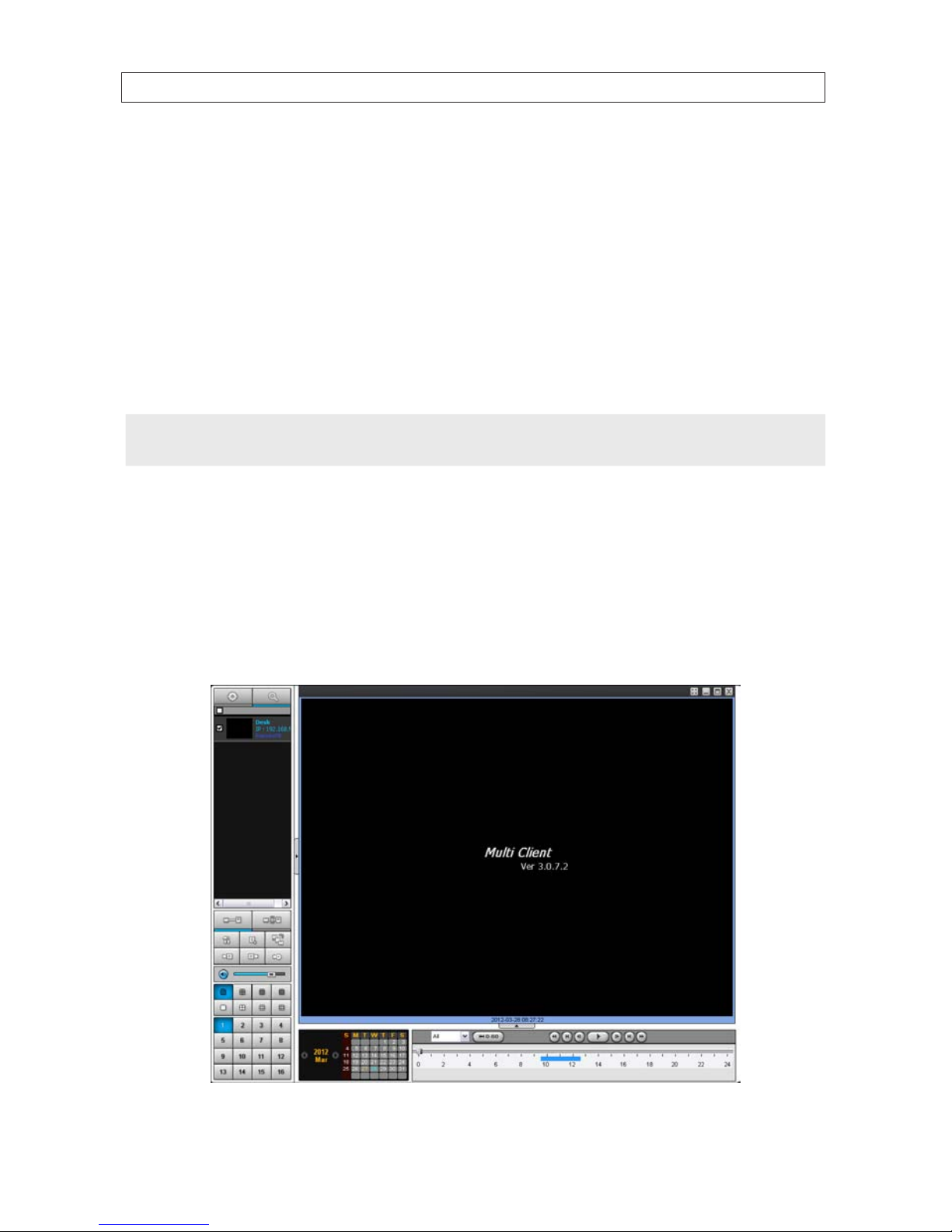
79H.264 DVR User Manual
SECTION 8: MULTI CLIENT SOFTWARE
8.5.3 Record
Video recording of the live screen can be manually started and stopped by clicking the Record button. When video is being
recorded, the Record button is highlighted blue. To stop recording, click the Record button again. By default, recorded video is
saved in the path specied in the Setup / General menu.
8.6 Remote playback and backup
The Multi Client can be used to search for and playback video clips in the DVR. Video clips can then be backed up to a local USB drive
or disk.
NOTE
The Event List may provide valuable information on when alarms and other events occurred. To open the Event List, click the
Events List button.
8.6.1 Remote playback
To search for and recorded video from the DVR:
1. At the Multi Client initial screen, connect to the DVR.
2. Click the Remote playback button. The client will open a Search mode window.

80
SECTION 8: MULTI CLIENT SOFTWARE
Table 21. Multi Client search window components
Button Function Description
FUNCTIONS
SETUP: Opens t he Setup menu
CAPTURE: Capture a still image of the s creen/camera.
EVENT LIST: Displays logge d DVR events.
MARK IN: Set the s tart time at the marker position
MARK OUT: Set the end t ime at the marker position
BACKUP: O pens a menu to backup the sect ion of video between the MARK IN
time and M ARK OUT time
AUDIO Adjust the volume. T he audio is on or muted by clicking t he speaker icon.
MULTI-DVR DISPLAY/
MULTI-CHANNEL
DISPLAY MODE
Display multiple DVRs
Selec t a split-scre en mode 1-, 4-, 9-, or 16- channel display.,
Channel selec t S elect a channel.
CALENDAR
In the calendar f rame, days wit h recorded video are co lored in light tan. Click
the date of the recorded video you want to nd or play. Dates colored tan have
data recorded. The date colored blue is the date selected; the timeline shows
when dat a was recorded on that day.
TIMELINE Bar
Display s a timeline for the date selected in th e calendar frame. Time spans when
video is recorded are marked in blue. To expand the display for an hour when
video w as recorded, drag the marker to t he hour you want to e xpand, then click
the 0 - 60 bu tton (located below the time line).
PLAYBACK BUTTONS
Use the playbac k buttons to control v ideo playback. The playbac k buttons are
labele d with the standard icons use d for video play control.
3. Select the DVR (checkbox) of the unit you want to see recorded video from.
4. In the calendar frame, click the date when the video of interest was recorded.
5. Drag the marker on the timeline to the time at which you want to play recorded video.
Marker
To expand the hour within which the marker lies, click the 0 - 60 button above the timeline.
6. Click the PLAY button to begin playing video at the marker position.

81H.264 DVR User Manual
SECTION 8: MULTI CLIENT SOFTWARE
8.6.2 Backing up video from the DVR on the Multi Client PC
Video recorded in the DVR can be backed up on the PC where the Multi Client is installed. Video clips are saved in AVI or NFS format.
1. At the Multi Client, connect to the DVR.
2. Click the Remote playback button. The client will change from Live mode to the Search mode.
3. Select the DVR (checkbox) of the unit you want to see video from.
4. In the calendar frame, click the date when the video of interest was recorded.
5. Drag the marker on the timeline to the time at which you want to play recorded video.
Marker
To expand the hour within which the marker lies, click the 0 - 60 button above the timeline.

82
6. Play the video to determine the time where you want to start backing up a clip, then stop the playback and click the MARK
IN button.
7. Continue playing the video to determine the time where you want to end the clip, then stop the playback and click the
MARK OUT button. The time span between the MARK IN and MARK OUT times will be highlighted in dark green.
Mark In Mark Out
8. To backup the video clip, click the BACKUP button. The Backup menu window will open.
9. In the Backup menu, select the options you want, then click OK.
10. A pop-up window will appear when the backup operation is complete. Click OK to close the Backup operation.
NOTE
Video backup can take several minutes to complete, depending on the number of channels selected and the duration of the clip.
8.7 Local playback
Use the Local Playback feature to play video recorded by the Multi Client record feature and saved on the local PC. To play these
recordings:
SECTION 8: MULTI CLIENT SOFTWARE

83H.264 DVR User Manual
SECTION 8: MULTI CLIENT SOFTWARE
1. Click the Local playback button. The playback window will open.
2. In the directory frame, select the site(s) you want to play recordings of. The calendar will indicate which days have recorded
video les on the local PC.
3. Click the day of the recording you want to play, then drag the marker to the time when video was recorded.
Click the 0 - 60 button above the timeline to expand the time scale.
4. Use the video play control buttons above the timeline to play the video.

84
8.7.1 AVI backup during playback
Video recorded by the Multi Client is saved on the local PC in .NDB le format. To save the video clip of a recorded le in .AVI le
format (compatible with most media players), perform a backup operation:
1. Play the video le that contains the segment you want to save in .AVI format. (See Local playback above.)
2. Play the video to determine the time where you want to start backing up a clip, then stop the playback and click the MARK
IN button.
3. Continue playing the video to determine the time where you want to end the clip, then stop the playback and click the
MARK OUT button. The time span between the MARK IN and MARK OUT times will be highlighted in dark green.
Mark In Mark Out
4. To backup the video clip, press the BACKUP button. The Backup menu window will open.
SECTION 8: MULTI CLIENT SOFTWARE

85H.264 DVR User Manual
SECTION 8: MULTI CLIENT SOFTWARE
5. In the Backup menu, select the options you want, including the AVI le format, then click OK.
6. A pop-up window will appear when the backup operation is complete. Click OK to close the Backup operation.
NOTE
Video backup can take several minutes to complete, depending on the number of channels selected and the duration of the clip.
NOTE
If your media player cannot play the le backed-up in AVI le format, it probably doesn’t use the correct CODEC. Update your
H.264 CODEC and retry playing the le.

86
SECTION 9: WEB CLIENT
SECTION 9
Web Client
Web Client, the network-based administrative interface to the DVR, is used with Microsoft Internet Explorer® (IE) tool used to
monitor and control the DVR remotely. To use this feature, the DVR must rst be congured and connected to a network. The URL
(internet address) of the DVR depending the path used to connect to it.
If your computer is networked on the same local network as the DVR you are accessing, the URL is the IP address shown in the DVR
System Information window. In the example shown below, the URL is the IP ADDRESS: 192.168.5.60.
If you are accessing your DVR across the internet, your DVR may be addressed through a port forwarded by a router or a device
that connects the network with the DVR to the Internet, or through a connection to a DDNS web service such as ddnscenter.com
(preferred). To use this service for accessing your DVR across the internet, refer to ddnscenter.com for more information.
9.1 Connecting to the DVR with IE
After your DVR is setup on a local LAN, use IE to connect to it to verify the DVR connectability. This connection increases exibility for
monitoring and conguring your security system.
Before you can connect to the DVR with IE, the (default) security settings in IE are modied slightly to allow it to install an software
from the DVR.
1. At your PC, load IE.
2. Open the IE Tools pull-down menu and select Internet Options. Click the Security tab.

87H.264 DVR User Manual
SECTION 9: WEB CLIENT
3. Click the Custom Level... button. In the Settings list, change the following settings from Disable to Prompt:
Download unsigned ActiveX controls
Initialize and script ActiveX controls not marked as safe for scripting
Click OK, then click YES in the Warning window.

88
SECTION 9: WEB CLIENT
In the Internet Options window, click Apply, then click OK to close the window.
NOTE
If your computer operating system is Windows Vista or Windows 7, User Account Control can interfere with the normal
operation of the DVR user interface. To disable UAC, open the Control Panel > User Account > User Account window, clear the
Use User Account Control (UAC) to help protect your computer check box, then click OK. A computer restart may
be required.
4. In the IE URL eld, enter the IP address assigned to your DVR. Using the example shown above, enter:
192.168.5.60
5. If a message appears to load the SCTechnologies Client, click Install. Follow the prompts to Install the program.
After the Web Client loads, the Connect screen will be available.

89H.264 DVR User Manual
SECTION 9: WEB CLIENT
WebViewer
Status
Frame
WebViewer
View
Screen
Table 22. Web Client Live window components
Button Function Descr iption
TIMES TAMP
Times tamp window. When Web Client is not connected, it shows the PC time. When
Web Client is connected and showing live video, it indicates th e DVR timestamp.
When Web Client is playing video, it is t he timestamp of the video f rame.
CONNEC T / DISCONNECT Used to initiate a connection to a DVR, or disconnec t from a DVR.
SEARCH / LIVE Used to switch between the search window and the live mode window.
CHANNEL SELEC T Used to select and display one channel.
SPLIT SCREEN SELECT Used to select the scre en split: 2x2, 3x3, 4x4

90
SECTION 9: WEB CLIENT
Button Function Descr iption
PTZ DIRECTIONAL
CONTRO l
Click th e center button until PT appear s. Click the PTZ camer a to select it, then click
the dire ctional icons to move t he camera in that direc tion.
PTZ Zoom/Focus Cont rol
Click th e center button until ZF appear s. Click the PTZ camera to select it, then click the
upper an d lower icons to zoom in and out, click the right and left icons to fo cus.
AutoScan, Tour, OSD
Setup b uttons
AutoSc an chanes the dial control to play/stop the autoscan feature, and select the
camera channel to autoscan. Tour displays channels sequentially in f ull screen mod e.
OSD Setup opens the Web Client on- screen display controls menu s.
Mic On/O , Audio On/
O, Volume Control
Use the se features to control the audio sys tem. When the Mic and Audio icons are
gray, thos e components are disabled.
Capture, Pause, Preset,
Setup b uttons
Capture: us ed to capture a ph oto of the screen.
PAUSE: use to f reeze the screen in live mode, or fre eze playback.
Preset:
Setup: Opens the DVR Setup menu sys tem
6. Click the Connect button. A Connect webpage diaglog menu window will open.
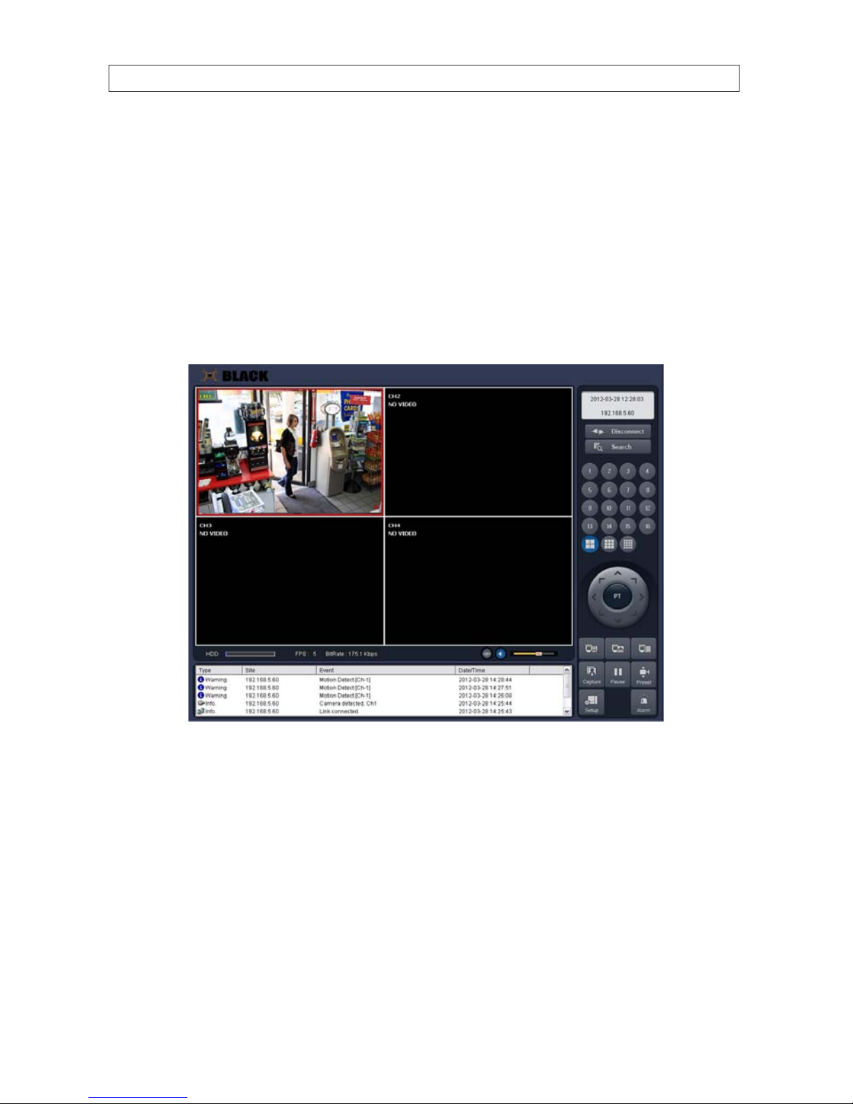
91H.264 DVR User Manual
SECTION 9: WEB CLIENTS
In the Webpage Dialog menu, enter:
— Server address: For access across a local network (Web Client PC on the same subnet as the DVR), use the DVR IP
address. For access from the internet, use the DDNS URL (if available) or router/modem IP address with forwarded
port number.
— Port: Port number of the DVR (default = 5445)
— ID: Username. The default username for the DVR is Admin.
— Password: Password for the user ID. For ID Admin, the default password is 1111.
7. Click Connect to connect to your DVR. After connecting to the DVR, the connection status will appear in the Status frame,
and the DVR camera views will appear in the view screen.
9.2 Setup
The Setup feature enables you to congure your DVR through Web Client. The Setup menu system includes the following submenus:
Display, Record, Device, Storage, System, Network, and Upgrade. Components in these submenus are similar to those in the DVR
SETUP submenus (refer to Section 3 for denitions).
To enter the Setup menus after connecting to your DVR, click the Setup button in the lower right corner of the window, enter the
Admin password in the WEB SETUP window, then click LOGIN. After several seconds, the DISPLAY menu will appear.

92
SECTION 9: WEB CLIENT
After making changes to a menu, click the APPLY button. To revert to the current settings (the original settings or the settings
during the previous APPLY). click RELOAD. To exit the Setup menus, click the T icon in the upper right corner to close the window.
9.2.1 Setup DISPLAY
Use the Display submenu to setup the sequential viewing of the channel and adjust the video quality of the display.
9.2.2 Setup RECORD
Use the Record submenu to setup the recording mode for each camera channel.
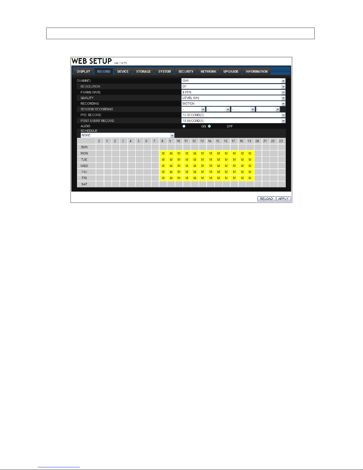
93H.264 DVR User Manual
SECTION 9: WEB CLIENT
9.2.3 Setup DEVICE
Use the Device submenu to setup the Device, Alarm out, PTZ, and Spot Out conguration.

94
SECTION 9: WEB CLIENT
9.2.4 Setup STORAGE
Use the Storage submenu to setup the recording conguration of the DVR HDD.
 Loading...