

Observint Technologies BLK-CPD700, BLK-CPD700R, BLK-CPV700, BLK-CPV700R User Manual
BLK-CP700 Series
High Performance 700TVL
Varifocal CCTV Dome Cameras
User Manual
Products: BLK-CPD700, BLK-CPD700R, BLK-CPV700, BLK-CPV700R
BLK-CPD700 and BLK-CPV700R
Please read this manual before using your camera, and always follow the instructions for
safety and proper use. Save this manual for future reference.
BLK-CPD700-CPV700_CM
4/10/14
ii
WARNING
!
Changes or modications not expressly approved by the manufacturer could void the user’s authority to operate the
equipment.
CAUTION
To prevent electric shock and risk of re hazards, do NOT use other than the specied power source.
REGULATORY NOTICE
This device complies with Part 15 of the FCC Rules. Operation is subject to the following two conditions:
(1) This device may not cause harmful interference, and
(2) This device must accept any interference received, including interference that may cause undesired operation.
This equipment has been tested and found to comply with the limits for a Class A digital device, pursuant to Part
15 of the FCC Rules. These limits are designed to provide reasonable protection against harmful interference in a
residential installation.
This equipment generates, uses, and can radiate radio frequency energy and, if not installed and use in
accordance with the instructions, may cause harmful interference to radio communications.
Operation of this equipment in a residential area is likely to cause interference, in which case the user will be
required to correct the interference at his own expense.
LEGAL NOTICE
Observint Technologies (Observint) products are designed to meet safety and performance standards with the use
of specic Observint authorized accessories. Observint disclaims liability associated with the use of non-Observint
authorized accessories.
The recording, transmission, or broadcast of any person’s voice without their consent or a court order is strictly
prohibited by law.
Observint makes no representations concerning the legality of certain product applications such as the making,
transmission, or recording of video and/or audio signals of others without their knowledge and/or consent. We
encourage you to check and comply with all applicable local, state, and federal laws and regulations before
engaging in any form of surveillance or any transmission of radio frequencies.
Other trademarks and trade names may be used in this document to refer to either the entities claiming the marks
and names or their products. Observint disclaims any proprietary interest in trademarks and trade names other than
its own.
No part of this document may be reproduced or distributed in any form or by any means without the express written
permission of Observint
© 2013, 2014 by Observint Technologies. All Rights Reserved.
11000 N. Mopac Expressway, Building 300, Austin, TX 78759
For Sales and Support, please contact your distributor.

iii
High Performance 700TVL CCTV Dome Camera User Manual
Table of Contents
SECTION 1 Introduction .......................................................................1
1.1 Features ............................................................................1
1.1.1 What’s in the box ................................................................2
1.1.2 Tools you need ..................................................................2
1.1.3 Optional mounting brackets .......................................................3
SECTION 2 Installation ........................................................................4
2.1 General Guidelines ...................................................................4
2.2 Mounting the camera. . . . . . . . . . . . . . . . . . . . . . . . . . . . . . . . . . . . . . . . . . . . . . . . . . . . . . . . . . . . . . . . .4
2.2.1 Mounting the camera onto a surface ...............................................4
2.2.2 Installing the camera with a mounting bracket. . . . . . . . . . . . . . . . . . . . . . . . . . . . . . . . . . . . . . .7
2.3 Camera FOV adjustments ..............................................................9
SECTION 3 Software Setup ....................................................................11
3.1 LENS ..............................................................................11
3.2 EXPOSURE .........................................................................12
3.3 WHITE BAL .........................................................................15
3.4 DAY/NIGHT .........................................................................16
3.5 3DNR. . . . . . . . . . . . . . . . . . . . . . . . . . . . . . . . . . . . . . . . . . . . . . . . . . . . . . . . . . . . . . . . . . . . . . . . . . . . . .18
3.6 SPECIAL ...........................................................................19
3.7 Adjust .............................................................................24
3.8 RESET .............................................................................25
3.9 EXIT ...............................................................................26
SECTION 4 Cleaning ..........................................................................27
SECTION 5 Specications .....................................................................28
APPENDIX A Troubleshooting ...................................................................30
A.1 IR level adjustment ..................................................................30
APPENDIX B Camera Dimensions ................................................................31

iv
Precautions
• This camera should be installed by qualied personnel only.
• There are no user serviceable parts inside.
• Do not disassemble this camera other than to make initial adjustments.
• Use a UL approved regulated 24 volt AC or 12 volt DC power supply.
• Use appropriate low voltage power cable to prevent re or electrical shock.
• Please insure that your installation area can support the weight of the camera.
Handle this camera carefully
• Do not use a strong or abrasive detergent when cleaning the camera.
• Do not install near cooling or heating devices.
• Do not install the camera in extreme temperature conditions. Use the camera in environments where temperature
is within 14°F to 122°F. Use adequate ventilation if a camera is installed where high temperatures may occur.
• Do not install or use the camera in an environment where the humidity is high. Very high humidity levels can
reduce image quality.
• Do not install the camera under unstable lighting conditions. Severe lighting change or icker can cause the camera
to work improperly.
• Do not touch the front lens of the camera. Be careful not to leave ngerprints on the lens or camera dome.
• Do not drop the camera or subject it to physical shocks.
• Do not expose the camera to rain or spill liquids on it. If it gets wet, wipe dry immediately. Liquids can contain
minerals that corrode the electronic components.
• Do not expose the camera to radioactivity. If exposed to radioactivity the CCD will fail.
• Do not disassemble the camera. There are no user-serviceable parts inside it.
• Do not drop the camera or subject them to physical shocks. It can cause malfunctions to occur.
• Never point the camera at a strong light, or exposing it to a spotlight or an object reecting the strong light.
Smear or blooming may occur, and it can damage the image sensor.
• Before applying power to the camera, check the power source to ensure that it is within specications.
1
High Performance 700TVL CCTV Dome Camera User Manual
SECTION 1: INTRODUCTION
SECTION 1
Introduction
These high performance CCTV dome cameras feature a very high resolution Sony® CCD sensor providing 700 TVL, dual voltage
range (24 Vac, 12 Vdc), and on-screen display (OSD) for control and setup. The BLK-CPV700 and BLK-CPV700R cameras feature a
vandal-proof case and indoor/outdoor
1.1 Features
• High resolution: color 700 TV Lines
• DIS (Digital Image Stabilizer) feature stabilizes the video image when the camera is out of focus due to wind or climate.
• DC Auto Iris varifocal Lens(2.8-12 mm)
• OSD control functions
• Vandleproof, indoor/outdoor enclosure (BLK-CPV700, BLK-CPV700R only)
• Smart-IR produces vivid images in total darkness - True Day/Night with ICR (BLK-CPD700R, BLK-CPV700R only).
• Smart 3DNR prevents image blurring of moving object. Activates only if moving objects are detected.
• Defog function improves the clarity of images taken in poor conditions such as fog, smoke, rain or snow.
• Customizable backlight compensation (BLC) and motion detection (MD) areas
• In limited and low light conditions, Sens-Up (maximum x256) helps produce more visible and clearer images.
• Motion detection zones for up to 4 areas
• Privacy masking for up to 8 areas
• Signal/Noise ration 52 dB
• Dual power (24 Vac / 12 Vdc) option
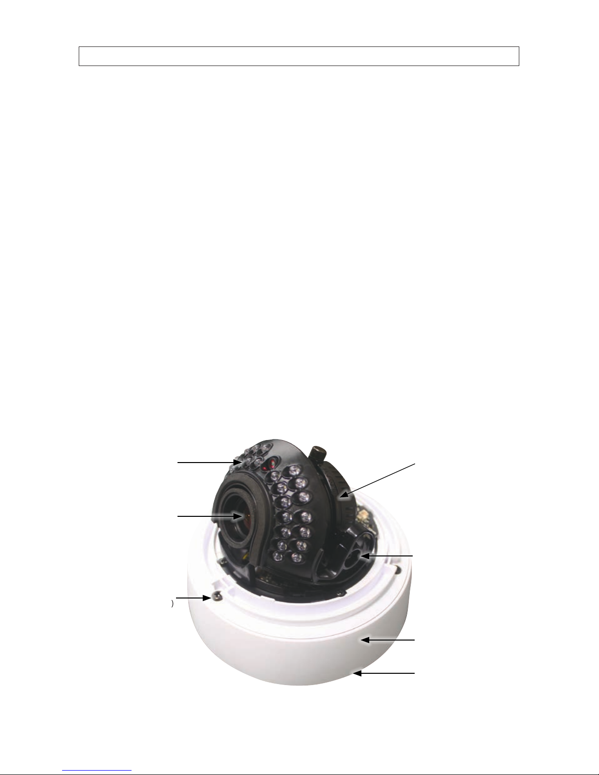
IR LEDs
(BLK-CDP700R
BLK-CDV700R
only)
Base
Base seal
(BLK- CPV700
series only)
Camera module
Gimbal mount
DC Auto-iris
Varifocal lens
(2.8mm - 12mm)
Camera module to
base captive screw (3)
BLK-CPD700R camera (dome removed)
2
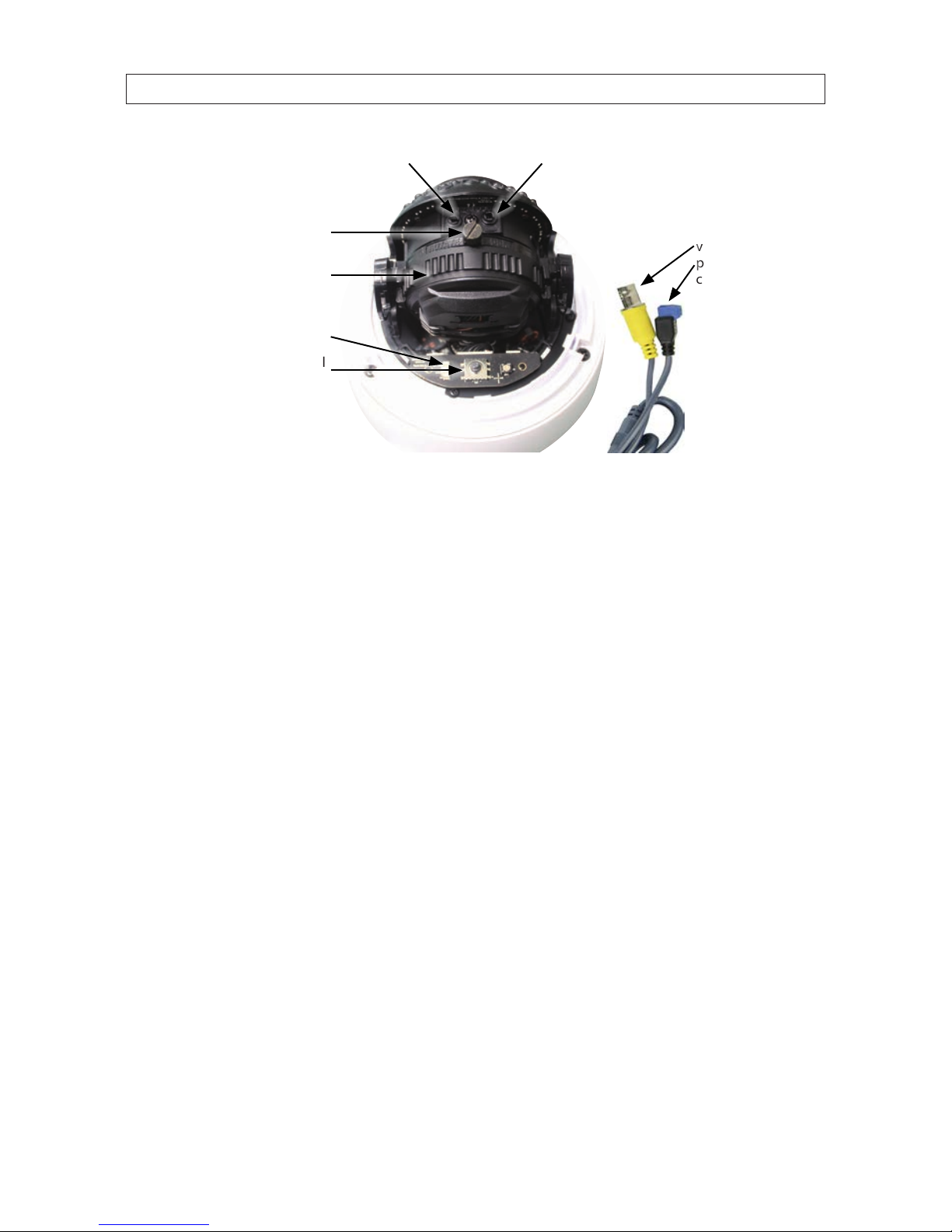
Focus adjustZoom adjust
Rotate lock screw
Rotate ring
OSD control
board
Drop cable
video,
power,
connectors
Video test port
BLK-CPD700R camera module back
1.1.1 What’s in the box
Your camera includes the following:
• Camera assembly
• Four (4) coarse-threaded screws and wall inserts to secure the base to the mounting surface
• Torx® (T-20) L-wrench for removing the dome (BLK-CPV700 series only)
• Power adapter cable (with female plug) for power drop cable
• Video test port to BNC adapter cable
• Screw driver
• This manual
1.1.2 Tools you need
To install the camera, you will need:
• 12 Vdc or 24 Vac power source
• Tools for mounting the camera
• Phillips #1 and #2 screwdriver
• Video and power extension cables, if needed
• Hand-held CCTV video setup monitor (optional)
SECTION 1: INTRODUCTION
3
High Performance 700TVL CCTV Dome Camera User Manual
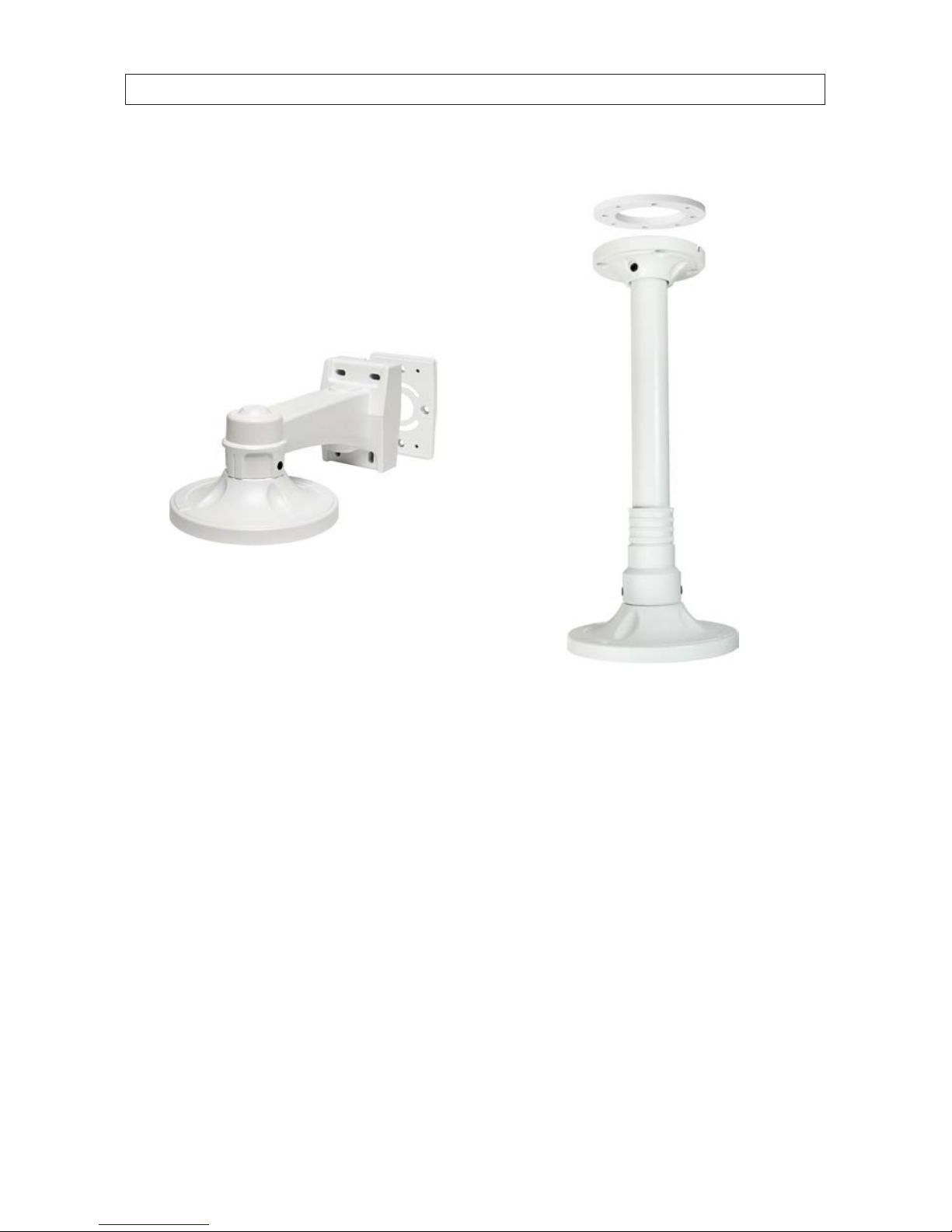
1.1.3 Optional mounting brackets
Two optional mounting brackets are available for the BLK-CP700
series cameras:
• BLK-WALLMT: Wall mount bracket
• BLK-PENDMT: Pendant mount bracket
BLK-WALLMT bracket
BLK-PENDMT bracket
SECTION 1: INTRODUCTION
4
SECTION 2: INSTALLATION
SECTION 2
Installation
2.1 General Guidelines
• Camera Lens: Handle the camera dome carefully to prevent scratching or soiling the dome and lens. If the dome or lens
becomes soiled, clean it only with approved products. See the Cleaning section later in this manual.
• Monitor impedance: Set the monitor impedance switch to 75Ω.
• Power supply: To avoid re or shock hazard, use only a UL listed power supply.
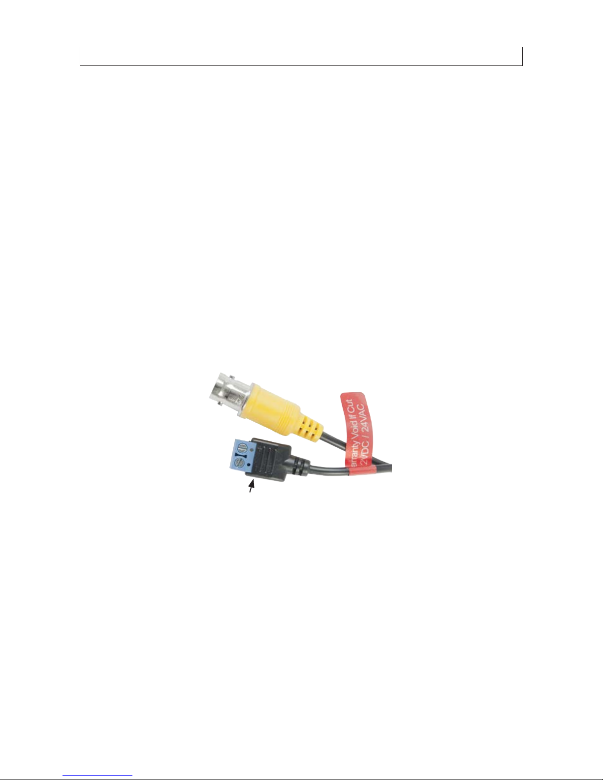
• Camera drop cable: The camera drop cable includes two connectors:
— Power connector (blue terminal block) – Use 24 Vac power source (AC24V 1A adapter) or 12 Vdc power source
(DC12V 1A adapter). When connecting 12 Vdc power to the camera power drop, observe the polarity shown on the
terminal block.
— Video coax connector (BNC, yellow sleeve) – for transmission of the video signal across coax (75 Ω) cable.
Video connector
Polarity indicators
Power terminals
Drop cable connectors
2.2 Mounting the camera
The camera can be mounted onto an electrical box, mounting bracket, or at surface with sucient strength to support it.
2.2.1 Mounting the camera onto a surface
When the camera is surface mounted, the drop cable can be routed through a hole in the center of the base and through the
mounting surface, or the side of the base. 3/4" conduit can be attached to either hole for the protection of the drop cable.

5
High Performance 700TVL CCTV Dome Camera User Manual
SECTION 2: INSTALLATION
1. Remove the camera dome cover from the camera. If you have a BLK-CPD700 series camera, use a coin to pry o the cover. For
BLK-CPV cameras, loosen the four captive dome screws using the Torx L-wrench provided.
2. Remove the camera module from the base by loosing the three captive screws that secure the camera module to the base.
3. Determine (and acquire, if needed) the best type of fasteners for attaching the camera to the mounting surface. The
mounting screws and wall inserts provided are adequate for most surfaces.
4. Using the camera base as a guide, mark the location of the screws that anchor the base to the mounting surface. For
mounting the camera to a surface, mark the four screw locations four holes. See the photo below. If you are routing the drop
cable through the hole in the base and then through the mounting surface, also mark the position of the hole in the center of
the base for the drop cable.
Screw locations for
surface mount
Hole in
base for
drop cable
(conduit)
Cable channel
(between base and surface)
BLK-CPD700 series camera base

6
SECTION 2: INSTALLATION
Screw locations for
surface mount
Hole in
side for
drop cable
(conduit)
Hole in
base for
drop cable
(conduit)
Screw locations
for bracket mount
Cable channel
(between base and seal)
BLK-CPV700 series camera base
5. Drill holes for the screws that anchor the base to the mounting surface. The four (4) course-threaded screws and wall inserts
provided are sucient for mounting the camera to most surfaces. However, other fasteners may be more appropriate.
6. Drill a 3/4” hole through the mounting surface for the drop cable, if necessary.
7. Route the camera drop cable through the base as planned.
8. If you are installing a BLK-CPV700 series camera, position the base seal appropriately onto the base.
9. Anchor the base to the mounting surface using appropriate fasteners.
10. Reattach the camera module to the base. Do not install the dome cover at this time.
11. Connect the camera drop cable video and power leads to a video and power extension cable as needed. If using 12 Vdc to
power your camera, observe the polarity marked on the power drop cable when connecting the power extension cable.
7
High Performance 700TVL CCTV Dome Camera User Manual
SECTION 2: INSTALLATION
CAUTION
When using 12 Vdc powering, use extreme caution to observe the polarity of the of the voltage applied to the camera.
The camera power drop cable connector center lead should receive +12 Vdc when measured to the shield (ground).
NOTE
Drop cable connectors are not waterproof.
12. Attach the far end of the video extension cable to video monitoring equipment such as a DVR.
13. Attach the far end of the power extension cable to a 12 Vdc or 24 Vac power source.
14. Apply power to the camera. Verify that video from the camera can be seen on the video monitor.
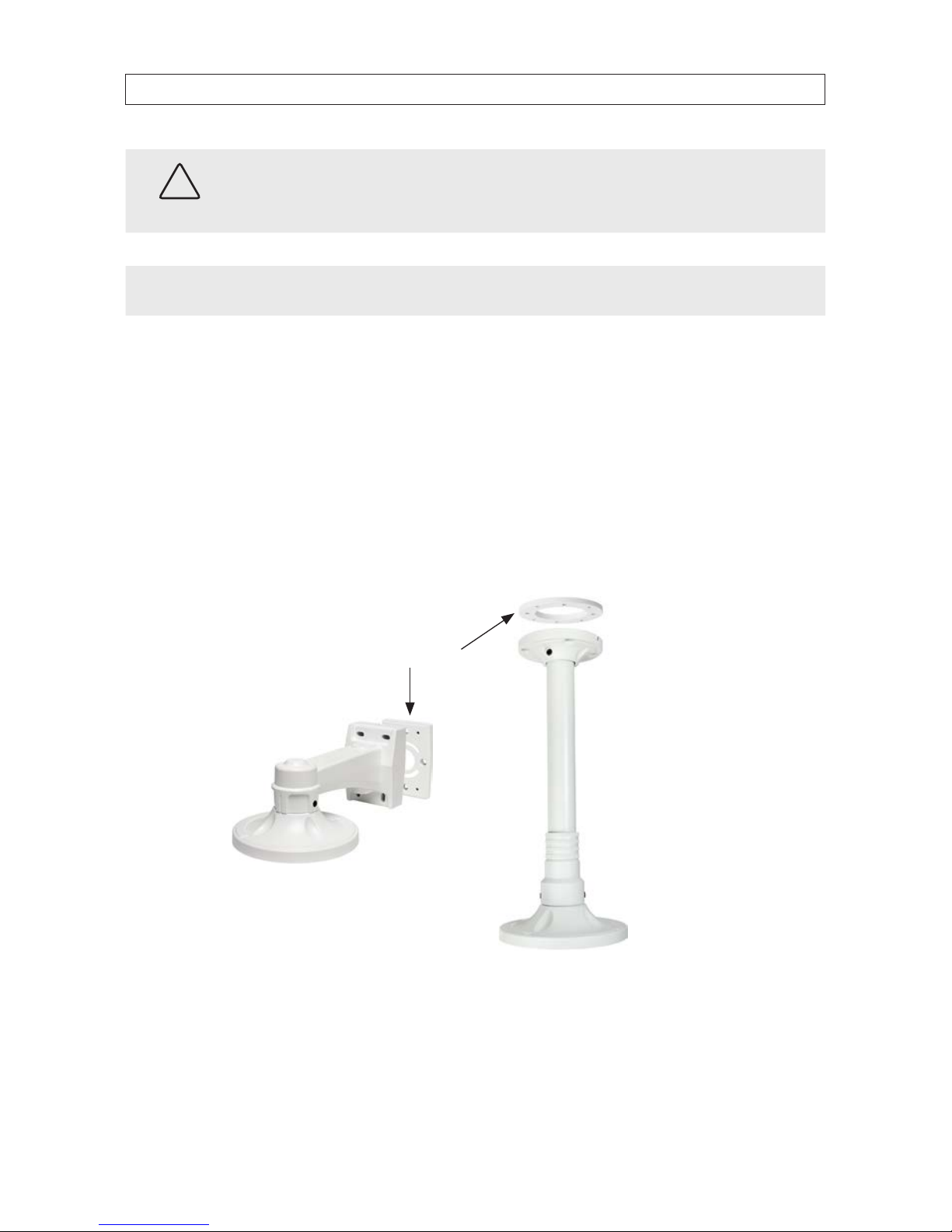
2.2.2 Installing the camera with a mounting bracket
The BLK-CPD700 series cameras and BLK-CPV700 and BLK-CPV700R cameras can be can be installed with either the BLK-WALLMT
(wall mount) or BLK-PENDMT (pendant (ceiling) mount) bracket.
BLK-WALLMT bracket
BLK-PENDMT bracket
Mounting plate
1. Use the bracket mounting plate as a template to mark the locations of the mounting screws and mounting surface through
hole for the drop cable. Note that the drop cable can be routed through a cable channel on the side of the bracket near the
mounting surface.
 Loading...