

Observint Technologies BLK-CPD207VH Quick Installation Manual
BLK-CPD207VH 650 Line Indoor
IR Camera Quick Installation Guide
This document guides you through the basic steps to inst all and use your BLK-CPD207VH camera. The
camera includes 2.8-12 mm lens, OSD setup menus, and 12 Vdc or 24 Vac powering.
Protective Sheet
PUSH
PUSH
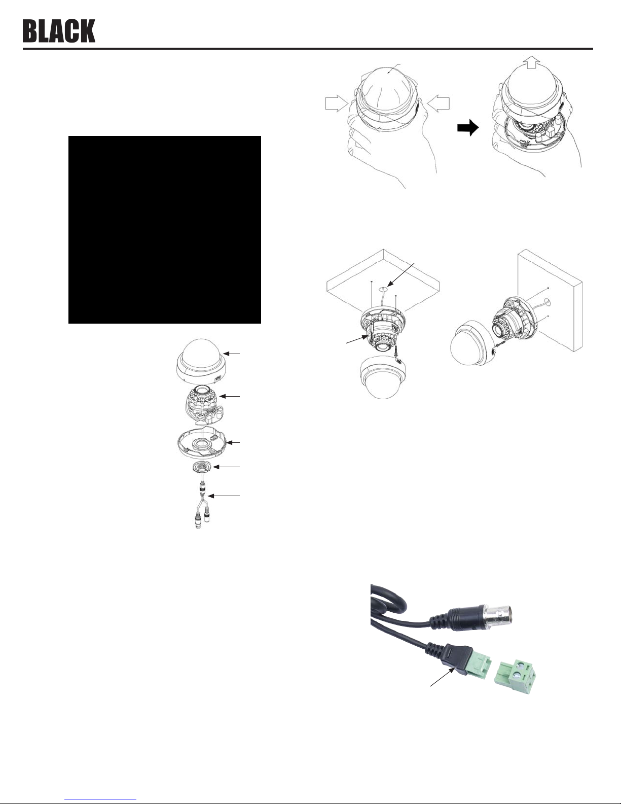
2. Using the base ass embly as a template, mark the locations for the mounting screws (2) and the hole
for the drop cable on the mounting sur face. Note that the drop cable can be routed through a c able
channel in the base an d exit on the side of the camera ass embly. The camera can be mounted on a
ceiling or wall.
Hole for
drop cable
Camera feature s include:
• 650 TV-line resolution in color, 720 TVL B / W
• Advanced Gen V DSP
• Smart DNR technology ecient ly reduces noise
in low light conditions
• 75 foot range with Smar t IR 24-LED IR LED array
• 3-axis camera gimbal - mountable on ceiling,
Dome
Camera
module
wall or sloped sur face
• Day & Night function (ICR)
• Support up to 8 privacy zones
• Digital Wide Dynamic Range (DWDR)
• Multi func tion : High Light Mask, Lens Shading
Base
Seal
Compensation, Smar t Motion Detection
• Smart IR technology greatly improves camera
image in B / W mode when the IR LED array is on
• Multi-language f ull OSD support
Drop
cable
Precautions
• Do not install the c amera outdoors.
• Do not install the c amera in locations subject to moisture or vibration.
• Do not scratch the camera, especially lens or dome cover.
• Operate the camera within the specied temper ature range 14 °F ~ 122 °F (-10 °C ~ 50 °C).
• Handle with care. Dropping it can cause serious damage to the camera.
• Do not install the c amera in locations where direc t sunlight shines onto or be reec ted onto the lens.
• Use a 12 Vdc, 1A regulated power adapter, or 24 Vac power adaptor.
Installation
1.
Remove the camera dome by pressing on the PUSH marks, then lif ting the dome o the base. Se e
below. Do not remove the protec tive sheet at this time.
Screw
3. Select the best fas teners to secure the camera to the surface on which it will to be mounted. Screws
provided with the camera are adequate many surface types.
4. Drill holes in the mo unting surface as required f or the mounting screws (wall inser ts, etc.), and the
drop cable, if nee ded.
5. Carefully route the camera drop cable through the drop c able hole or the cable channel in the bas e,
then attach the camera to the mounting surf ace.
6. Route a video / power extension c able between your monitoring equipment and the c amera. Note
that the ex tension cable connectors are usually dierent at each end.
7. Connect the v ideo / power extension cable to your camera, then conne ct the other end to a video
monitor and 12 Vdc or 24 Vac power source. NOTE: 1) The camera power cable provides a 2-pin
connector; an adapter with screw-down terminals is included in the box. 2) If powering the camer a
with 12 Vdc, observe the p olarity marked on the power drop cable.
Video drop cable
Power drop cable
12 Vdc polarity guide
Terminal adapter
8. Verify that you c an see video from your camera at the monitoring e quipment.
NOTE: An external video connector is provide d on the camera module. See “Maintenance board”
on page 2. The adapter c able provided with your camera o ers composite video through an RC A
connector to a lo cal monitor.
1 BLK-CPD207VH _CQ
9/26/12
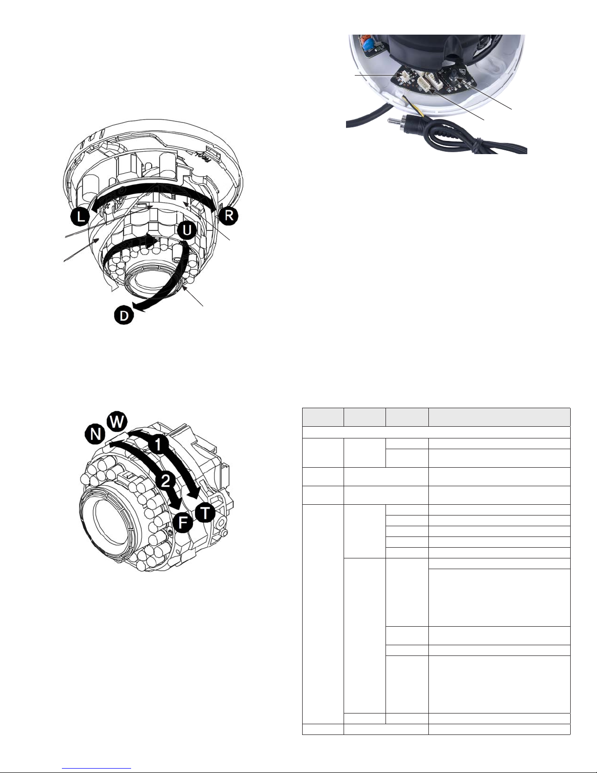
9. While observing the video image from your camer a, adjust the pan, tilt, and roll as follows to point
the camera at your surveillance target: Be careful not to displace the rubber r ing around the lens.
a. Pan adju stment: Grasp the gimbal assembly, then rotate it (0° ~ 360 °) left (L) or right (R).
b. Tilt adjustment: Grasp the protractor, then tilt it up (U) or down (D) (19° ~ 90°).
c. Roll adjustment: Grasp the camera module (within the gimbal), then rotate it (0° ~ 36 0°)
to set the horizon line of the image.
Protractor
(Tilt adjust)
Gimbal
(Pan adjust)
Camera module
(roll adjust)
grasp here
Rubber ring (seal)
10. While observing the video image from your camer a, adjust the zoom and focus set tings as follow
(see graphic below):
a. Zoom: Rotate the Tele (T) - Wide (W) r ing (1) to produce the best view of your surveillance
target.
b. Focus: Rotate the Near (N) - Far (F) ring (2) to produce the best image clarity.
11. Reinstall the dome.
Maintenance board
The maintenance board is part of the camera module assembly. It includes an exter nal video port, a debug
port, and a joystick for using the OSD menus.
External video
connector
Joystick
Debug port
Video adapter cable
Maintenance board and video a dapter cable
• External video connector: Use this connec tor with the adapter cable provided (2-pin to RCA) to
connect to a loc al monitor for observing video from the camera. This feature is useful dur ing camera
setup and troubleshooting.
• Debug por t: Maintenance port for engine ering use only.
• Joystick : Used for accessing and conguring the camera through t he on-screen display (OSD) menus:
The OSD menu structure is shown in the table below.
— Push the joystick down (toward the board) to open the OSD menu system, conrm a selection, or
open a submenu.
— Rock the joys tick toward the UP or DOWN to move vertically through the OSD menus.
— Rock the joys tick toward the LEFT or RIGHT to change the option displayed for an OSD p arameter.
To select the parameter, press the joystick down.
— Example: Using the joystick to setup the camera for high ACG (automatic gain control).
» While observing video from the camera, press the joystick down to open the OSD main menu.
» Rock the joys tick toward the UP or DOWN repeatedly until AGC is highlighted.
» Rock the joys tick toward the LEFT or RIGHT repeatedly until HIGH appears.
» Press the joys tick down to conrm the selec tion.
» Rock the joys tick toward the UP or DOWN repeatedly to highlight RETURN.
» Press the joys tick down to conrm the selec tion (RETURN: close the menu).
OSD Menu Struc ture
Funct ion
setti ng menu
1. EXPOSURE
Lens DC
AGC OFF, LOW, MIDDLE, HIGH
SENSE-UP
BACKLIGH T
3D-DNR OFF, LOW, MID, HIGH, AUTO Reduces n oise in low illumin ation (level sel ectable)
Selec t menu Sub-me nu Content s
Bright ness
E. Shut ter
AUTO, OFF, X2, X4, X8, X16, X32, X64,
X128, X256, X512, X1024
BLC LEVEL OFF, LOW, MID, HIGH : BLC funct ion, level sele ctable
TOP 0 ~ 15: Adjust top po sition of BLC zone
BLC
HLC
D-WDR SET LEV EL 0 ~ 20 : DWDR level a djust
BOTTOM 1 ~ 16 : Adjust bot tom positi on of BLC zone
LEFT 0 ~ 15: Adjus t left posit ion of BLC zone
RIGHT 1 ~ 16 : Adjust rig ht position of B LC zone
HBLC
MODE
HLC LEVEL 1 ~ 100 : Level adjust
MASK 1 ~ 4
0 ~ 99 : Adjust b rightness w ith a DC iris lens
AUTO, 1/60, 1/100FLK, 1/120, 1/250, 1/50 0, 1/1000, 1/2000,
1/4000, 1/1000 0, 1/100000 : Adjus t shutter sp eed
Sets th e AGC level. Note: You can n ot use Auto D&N chan ge mode
when AGC is o.
Use sense -up in low luminan ce (x2 ~ x1024)
OFF : Deac tivates HBLC f unction
MANUAL
HBLC LEVE L : OFF, LOW, MID, HIGH
Make a zone fo r HBLC:
TOP : 0 ~ 15
BOTTOM : 1 ~ 16
LEFT : 0 ~ 15
RIGHT : 1 ~ 16
ALL DAY : Activat es HBLC funct ion all day
NIGHT : Use t he functio n at night only
ON
Make a zone fo r HLC mask:
TOP : 0 ~ 33
BOTTOM : 1 ~ 34
LEFT : 0 ~ 4 4
RIGHT : 1 ~ 45
OFF : HLC MASK O FF
2 © 2012 Observint Technologies, Inc. All rights reserved.
 Loading...