

High Resolution Color Camera
1
INFORMATION - This equipment has been tested and found to comply with
limits for a Class A digital device, pursuant to part 15 of the FCC Rules & CE Rules.
These limits are designed to provide reasonable protection against harmful
interference when the equipment is operated in a commercial environment.
This equipment generates, uses, and can radiate radio frequency energy and, if
not installed and used in accordance with the instruction manual, may cause
harmful interference to radio communications.
Operation of this equipment in a residential area is likely to cause harmful
interference in which case the user will be required to correct the interference at
his own expense.
◆
Do NOT use power sources other than those specified.
◆
Do NOT expose this appliance to rain or moisture.
This installation should be made by a qualified service person and
should conform to all local codes.
The lightning flash with an arrowhead symbol, within an equilateral
triangle is intended to alert the user to the presence of uninsulated
dangerous voltage within the product's enclosure that may be of
sufficient magnitude to constitute a risk of electric shock to persons.
The exclamation point within an equilateral triangle is intended to alert
the user to the presence of important operating and maintenance
(servicing) instructions in the literature accompanying the appliance.
WARNING - Changes or modifications not expressly approved by the
manufacturer could void the user's authority to operate the equipment.
CAUTION : To prevent electric shock and risk of fire hazards:

■
Features
Warning ■
2
High Resolution Color Camera High Resolution Color Camera
3
Horizontal Resolution of 550 TV
Lines
Clear image quality has been achieved by
employing a SONY CCD with 410,000
(effective) pixels, which provides a
horizontal resolution of 550 TV lines.
Electronic IRIS
The electronic IRIS function enables
continuous automatic control of the
shutter between 1/60(1/50)~1/100,000
seconds.
PRIVACY Function
The PRIVACY function conceals the
areas not required to appear on
the image.
High Sensitivity
The built-in high sensitivity SONY COLOR
CCD enables a clear image even at
0.3Lux (0.1Lux B/W)
Programmable GAMMA Processing
Controlled by OSD Menu
The camera functions are controlled by
selecting text displayed on the monitor
screen.
Additional Functions
MOTION DETECTION, MIRROR,
SHARPNESS and COLOR ADJUST
functions are also available.
VIDEO/DC Drive Lens
The video drive lens and the DC drive lens
can be selected by the touch of a switch.
The camera requires periodic inspection.
Contact an authorised technician to carry out the inspection.
Stop using your camera when you find it malfunctioning.
If the camera emits smoke or is unusually hot for a long period,
a fire may be caused.
Do not Install the camera on a surface that can not support it.
If the camera is installed on an inappropriate surface, it may fall
and cause injury.
Do not hold plug with wet hands.
It could cause an electric shock.
Do not dis-assemble the camera.
It may result in an electric shock or other hazards.
Do not use the camera close to a gas or oil leak.
It may result in a fire or other hazards.

■
Contents
4
High Resolution Color Camera High Resolution Color Camera
5
Camera Operation
19
■ Settings
20
■ EXIT
32
ㆍ LENS
21
ㆍ SHUTTER
23
ㆍ WHITE BALANCE
24
ㆍBLC (Back Light Compensation)
25
ㆍ AGC (Auto Gain Control)
26
ㆍ ADJUST
27
ㆍ FUNCTION
28
- CAMERA ID
28
- DAY & NIGHT
29
- MIRROR
30
- MOTION DETECTION
30
- PRIVACY
31
- GAMMA
31
- LANGUAGE
32
- RESET
32
- RETURN
32
Specifications
35
Troubleshooting
33
Features
Precautions
Overview
Installation Procedures
■ Front View
■ Side View
■ Bottom View
■ Rear View
02
06
09
13
09
10
11
12
■ Lens
ㆍWhen Using Auto Iris Lens
ㆍWhen Using C/CS Mount Lens
■
Connecting a Monitor
■
Connecting Power
13
17
18
Components and Accessories
08

■
Precautions
Only use the camera under conditions
where temperatures are between
-10¡C and +50¡C. Be especially
careful to provide ventilation when
operating under high temperatures.
It can cause the image quality to be
poor.
Severe lighting change or flicker can
cause the camera to work improperly.
This is one of the most important parts of
the camera. Be careful not to leave
fingerprints on the lens cover.
Do not install the camera in
extreme temperature conditions.
Do not install or use the camera in an
environment where the humidity is high.
Do not install the camera under
unstable lighting conditions.
Do not touch the front lens of the
camera.
It can cause malfunctions to occur.
If it gets wet, wipe it dry immediately.
Liquids can contain minerals that
corrode the electronic components.
If exposed to radioactivity the CCD
will fail.
It can damage the CCD.
Do not expose the camera to rain
or spill beverage on it.
Do not expose the camera to
radioactivity.
Never keep the camera pointed
directly at strong light.
Do not drop the camera and protect
it from physical shocks.
Note
ㆍIf the camera is exposed to spotlight or object reflecting strong light,
smear or blooming may occur.
ㆍ Please check that the power satisfies the normal specification before
connecting the camera.
6
High Resolution Color Camera High Resolution Color Camera
7
■
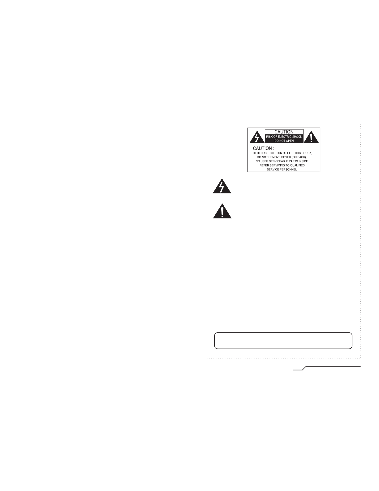
Components and Accessories
Overview ■
8
9
2.
Auto Iris Lens Connector Plug
3. C-Mount Adapter
4. Instruction Manual
1. Ultra High Resolution
WDR Color CCD Camera
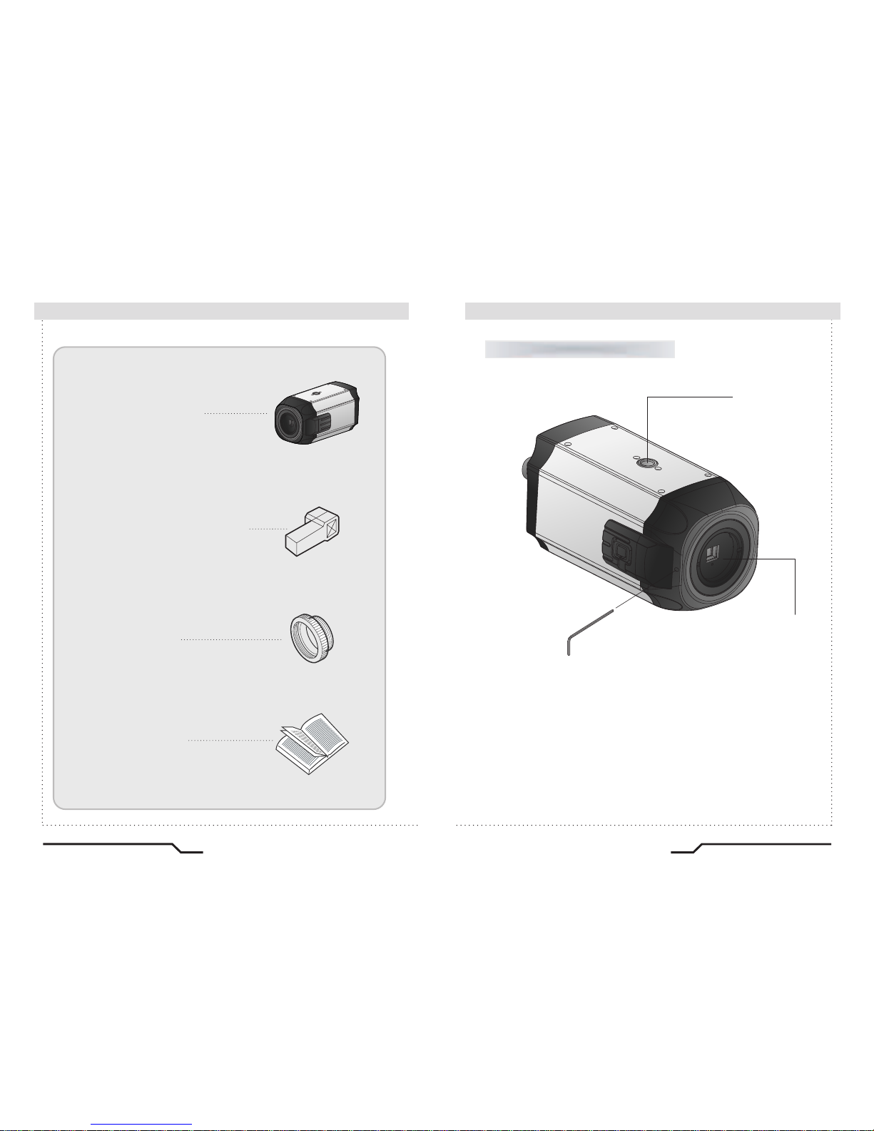
Front View
①Tripod Mounting Bracket Screw Hole
Used to fix the Tripod Mounting Bracket to the top of the camera.
②C-Mount Lens Adapter
Install this adapter to use a C-Mount Lens.
①
②
③
③Back Focus clamp screw
Loosen the clamp screw with a screwdriver before adjusting
the Back Focal length.
High Resolution Color Camera High Resolution Color Camera

■
Overview
10
11
④Auto Iris Lens Connector
Used to connect Auto Iris Lens plug.
Side View Bottom View
④
⑤Tripod Mounting Bracket Screw Hole
Used to fix the camera on a bracket or tripod.
The screw sizes for this hole are as follows:
1/4"-20 UNC (20 THREAD)
L:4.5mm±0.2mm (ISO standard),
or 0.197" (ASA standard)
L
⑤
High Resolution Color Camera High Resolution Color Camera
■
Overview
Installation Procedures ■
12
13
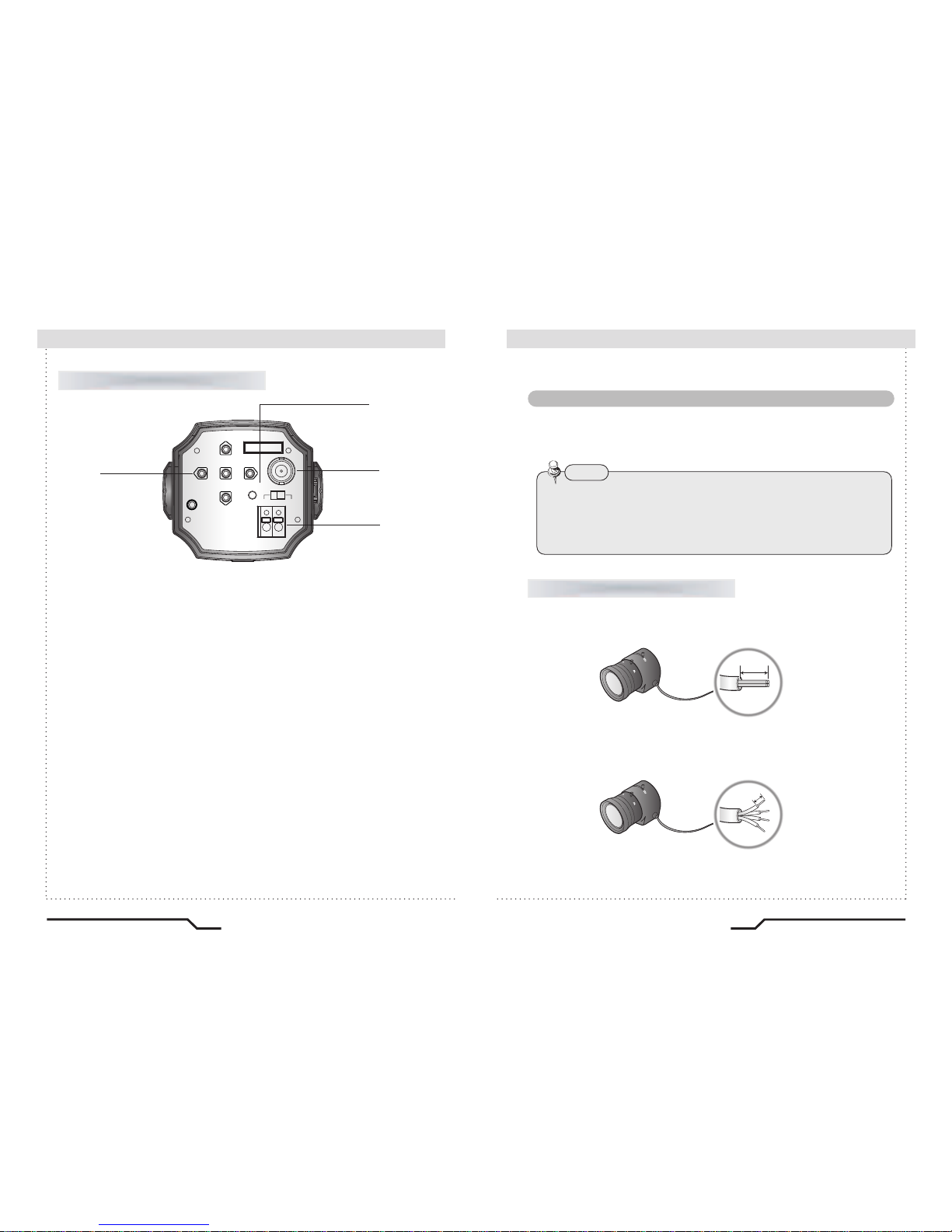
Rear View
⑥Function Setup Button
ㆍSET Button : Displays the menu on the screen. Press this button to confirm
status or after changing a selected item.
ㆍUp and Down Button : Used to move the cursor up or down in the menu
screen to select a desired menu item.
ㆍLeft and Right Button : Used to move the cursor left or right in the menu
⑦Power LED
When power is properly connected, this LED comes on.
⑧Video OUT Port
Video signals are output through this port. Connect this port to the Video IN
port
of a monitor.
⑨Power IN Port
Connect the power as specified for each model here.
Lens
The lens is not supplied with this camera. Purchase a lens suitable for
your environment. This camera accepts the auto iris lens and both
C-and CS-mount lens.
• It is recommended to use the DC type Auto Iris Lens to effectively
enjoy the major functions of this camera.
• Keep the lens surface clean, since if it is contaminated with dirt or
fingerprints the picture quality suffers.
Note
When Using Auto Iris Lens
1. Strip the insulation of the auto iris lens cable 8mm from the end.
.
2. Strip the insulation of the core of the auto iris lens cable to expose a
2mm length.
mm8 .xorppa
mm2 .xorppa
High Resolution Color Camera High Resolution Color Camera
REMOTE
VIDEO OUT
DC VIDEO
POWER
SET
F.G
AC24V/DC12V
⑥
⑦
⑧
⑨

■
Installation Procedures
3. Remove the cover of the auto iris lens connector plug and solder the lens
cable to the connector pin of the plug.
• For a Video Drive Lens
Pin 1: Red (Power)
Pin 2: NC
Pin 3: White (Video Signal)
Pin 4: Black (Ground)
• For a DC Drive Lens
Pin 1: Damping Pin 2: Damping +
Pin 3: Drive +
Pin 4: Drive -
14
15
When Using C/CS Mount Lens
Before installing a lens, identify whether the lens to be installed is a C-Mount
or CS-Mount. This camera is set for a CS-Mount Lens by default. To install a
C-Mount Lens, a simple modification is required.
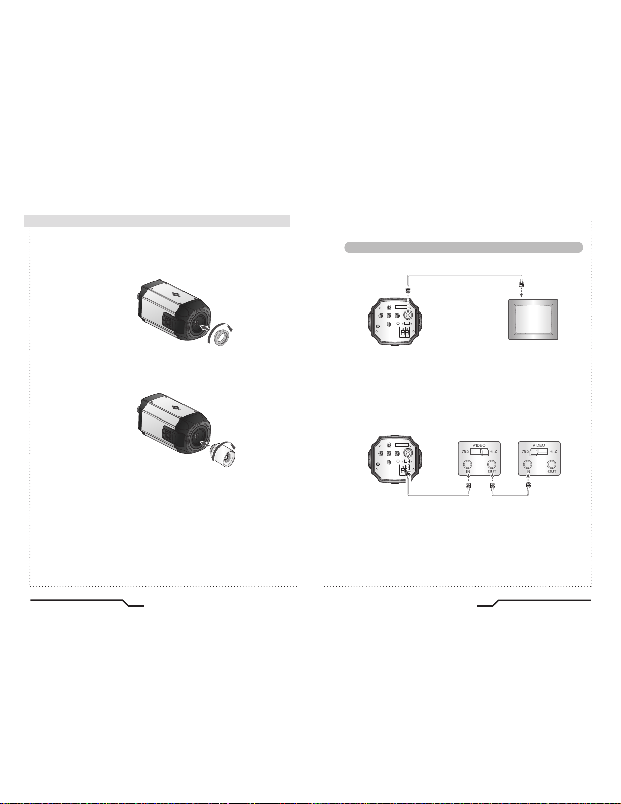
• When Using a CS Mount Lens
Remove the protective glass cover at the front of this product and turn the
CSMount Lens clockwise to install it. And set focus of camera using Back
Focus Control Lever of camera side after combining CS-Mount lens.
• Use the lens connector shown in the following figure. If the dimensions
of the connector are not correct, it may damage the camera, or the lens
may not be installed firmly.
• If the lens is too heavy, the camera becomes unbalanced and there may
be problems. Use a lens that weighs less than 450g.
• When adjusting the Automatic Level Control (ALC) of an auto iris lens,
use Av mode if available. If you use the Pk mode, the picture brightness
may change continuously.
Note
connector
Lens cable
No. 3 Pin
No. 1 Pin
No. 4 Pin
No. 2 Pin
C-Mount Lens: 10mm or less
CS-Mount Lens: 5mm or less
4. Fit the cover of the auto iris lens connector plug, remove the protective
glass cover from the front of the camera, and fasten the auto iris lens
by turning it clockwise.
High Resolution Color Camera High Resolution Color Camera
REMOTE
VIDEO OUT
DC VIDEO
POWER
SET
F.G
AC24V/DC12V
REMOTE
VIDEO OUT
DC VIDEO
POWER
SET
F.G
AC24V/DC12V
■
Installation Procedures
• When Using a C Mount Lens
1. Remove the protective glass cover at the front of this product and turn the
CMount Adapter clockwise to install it.
2. Turn the C-Mount lens clockwise to install it.
3. Set focus of camera using Back Focus Control Lever of camera side after
combining C-Mount lens.
Connecting a Monitor
16
17
Connect the Video OUT port on the rear panel of the camera to a monitor.
•
Since the connection procedure may differ depending on the type of monitor
or peripheral device to be connected, refer to the User Manual for the device
to be connected.
•
Make sure to turn off the device to be connected before making any connections.
• Turn the 75Ω/Hi-Z switches of interim display devices to the Hi-Z position,
and the switches of any final device to the 75 position.
CCD Camera
Monitor
CCD Camera
End monitor
Intermediate
High Resolution Color Camera High Resolution Color Camera
REMOTE
VIDEO OUT
DC VIDEO
POWER
SET
F.G
AC24V/DC12V
■
Installation Procedures
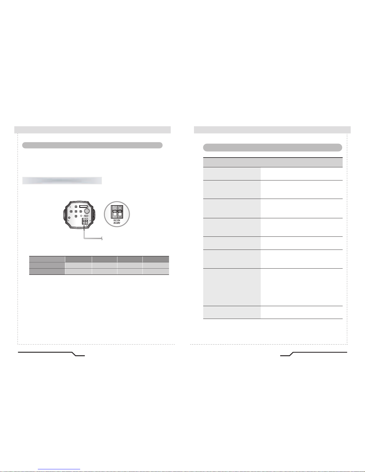
Since power specifications differ depending on the model, make sure to check
your model name and specifications before connecting power.
You can connect power as shown in the following figure.
•
Since the power specification supports both AC and DC, connect AC 24V, 500mA
Adaptor or DC 12V, 500mA Adaptor.
When the resistance value of copper wire is at [20°C(68°F)]
• As shown in the table above, voltage decreases as the wire gets longer.
Therefore use of an excessively long adaptor output line for connection to
the camera may affect the performance of the camera.
※Standard voltage for camera operation : DC 12V±10%, AC 24V±10%
※
There may be some deviation in voltage drop depending on the type of wire
and the manufacturer.
Connecting Power
For AC / DC power
#24(0.22mm2)
Copper wire size(AWG)
#22(0.33mm2) #20(0.52mm2) #18(0.83mm2)
Resistance value( /m)
0.0180.030
0.050
0.078
Voltage drop(V/m)
0.0060.0110.0180.028
18
19
High Resolution Color Camera High Resolution Color Camera
Camera Operation
■
■
Menu
SETUP menu
LENS (selection)
SHUTTER
(
condition and speed control)
WHITE BALANCE control
BLC
(Back Light Compensation)
AGC (Auto Gain control)
ADJUST
FUNTION
EXIT
ㆍMANUAL ㆍDC/VIDEO
ㆍFIXED ㆍAUTO ㆍFLK
ㆍATW
ㆍMANUAL
ㆍAWB ㆍFIXED
ㆍBLC AREA ㆍBLC RATIO
ㆍAGC CONTROL
ㆍCONTRAST ㆍCAMERA ID
ㆍCR - GAINㆍCB - GAIN
ㆍRETURN ㆍCAMERA ID
ㆍDAY / NIGHT ㆍMIRROR
ㆍMOTION ㆍPRIVACY
ㆍGAMMA ㆍLANGUAGE
ㆍRESET

Note
SETUP
LENS DC
SHUTTER FIXED
WHITE BAL. ATW
BLC OFF
3. Press the LEFT or RIGHT button to change modes.
ㆍWhen the LEFT or RIGHT button is pressed, available values and modes
are displayed in order. Keep pressing the button until you get to the
mode you wish to select.
4. Select 'EXIT' and then press the SET button to exit the set up menu.
This function is used to adjust the brightness of the screen.
1. When the SETUP menu is displayed on the screen, position the cursor to point
to 'LENS' by using the UP and DOWN buttons.
2. Select the type of the lens setting to use by pressing the LEFT or RIGHT button.
LENS (selection)
ㆍIf appears at the mode selected, it means that there is a sub-menu
which can be selected by pressing the SET button.
SETUP
LENS DC
SHUTTER FIXED
WHITE BAL. ATW
BLC OFF
AGC ON
ADJUST
FUNCTION
EXIT
Modes can be changed
using the LEFT and
RIGHT buttons.
Select the desired
menu item by
using the UP and
DOWN buttons.
■
Camera Operation
20
High Resolution Color Camera High Resolution Color Camera
21
REMOTE
VIDEO OUT
DC VIDEO
POWER
SET
F.G
AC24V/DC12V
Settings can be made using the 5 buttons located on the back of the camera.
■
Settings
1. Press the SET button
ㆍSettings can now be made. The SETUP menu is displayed on the monitor.
2. Select a menu item from the list available by using the UP and DOWN
buttons.
ㆍ
Funtions are selected using up and down buttons.
ㆍ
The selected position is displayed in blue.
SETUP
LENS DC
SHUTTER FIXED
WHITE BAL. ATW
BLC OFF
AGC ON
ADJUST
FUNCTION
EXIT
UP button
SET button
LEFT button
DOWN button
RIGHT button

High Resolution Color Camera
23
■
Camera Operation
22
High Resolution Color Camera
● DC/VIDEO : Auto Iris Lens selection
● MANUAL : Manual Lens selection
3. Press the SET button to return to the previous menu.
Note
When using an auto iris lens, the setting of the auto iris lens selection
switch, located on the back of the camera, must be on DC or VIDEO
depending on the type of the lens which being used.
(Refer to the picture on page 13)
ㆍ
The brightness of the screen can be adjusted in DC mode. The
brightness can be adjusted within the range of 0 ~255. The optimum
level of brightness can be achieved using this adjustment.
LENS DC
: RETURN
BRIGHTNESS 093
Auto or manual control can be selected.
1. When the SETUP menu is on the screen, position the cursor to point to
'SHUTTER' by using the UP and DOWN buttons.
2. Select the shutter mode by pressing the LEFT or RIGHT button.
● FLK : Select 'FLK' mode when flickering occurs on the screen
due to an imbalance between illumination and frequency.
NTSC Model:1/100, PAL Model: 1/120
● AUTO : Automatic control of the shutter speed is enabled.
When AUTO mode is on, the shutter speed is controlled
automatically according to the brightness of the scene.
● FIXED : The shutter speed can be controlled manually.
● MANUAL mode (256 steps) :
There are 256 pre-defined electronic shutter speeds in manual mode
available for selection; set according to environment conditions.
3. Select 'FIXED' mode for manual shutter speed adjustment.
ㆍ
Selectable speeds are from '1/60' to '1/120,000'sec (NTSC) and '1/50'
to '1/120,000'sec (PAL).
4. Press the SET button when the settings are completed.
SHUTTER (condition and speed control)
SETUP
LENS MANUAL
SHUTTER AUTO
WHITE BAL. ATW
BLC OFF
AGC ON
ADJUST
FUNCTION
EXIT

■
Camera Operation
24
High Resolution Color Camera High Resolution Color Camera
25
ㆍUnder the following conditions the WHITE BALANCE function may not operate
properly. In such cases, please select the AWB mode.
①
When the object's surroundings have a very high colour temperature
(eg, a clear sky and sunset)
②
When the object's surroundings are dark
③
If the camera directly faces a fluorescent light or is installed in a place where
there are considerable changes in illumination, the WHITE BALANCE function
may become unstable.
Note
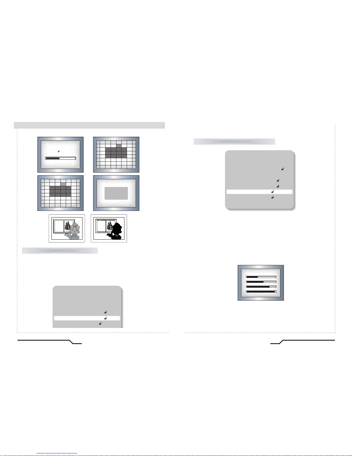
When there is a strong backlight behind the object, clear images of the
background as well as the object can still be obtained by using the
BACKLIGHT function.
1. Position the cursor to point to 'BLC' on the SETUP menu by using the
UP and DOWN buttons.
2. Select the value required by pressing the LEFT or RIGHT button.
3.
Press the SET button to enter the BLC AREA and BLC RATIO menus.
4. The BLC Area contains a grid of 64 squares where BLC can be
applied.
5. The BLC RATIO can now be adjusted (64 steps); a higher value
leads to a clearer image.
BLC (Back Light Compensation)
SETUP
LENS MANUAL
SHUTTER FLK
WHITE BAL. ATW
BLC OFF
AGC ON
ADJUST
FUNCTION
EXIT
SETUP
LENS MANUAL
SHUTTER FIXED
WHITE BAL. ATW
BLC OFF
The screen colours can be adjusted using the WHITE BALANCE function.
1.
Position the cursor to point to 'WHITE BAL' on the SETUP menu by using the
UP and DOWN buttons.
2. Select the mode you wish to adjust by pressing the LEFT or RIGHT buttons.
WHITE BALANCE
※Select one of the 4 modes below.
●
ATW
(Auto Tracking White Balance) : This mode can be used within the
colour temperature range 1,800˚K ~ 10,500˚K (eg, fluorescent light, outdoor,
sodium vapour lamp etc.)
●
AWB(Automatic White Balance)
: Press the SET button while the
camera is directed at a piece of white paper to obtain the optimum state
under current illumination. If the environment, including the light source,
changes the white balance will need to be adjusted again.
●
MANUAL : The manual adjustment mode enables finer adjustment.
Select ATW or AWB first then change to manual adjustment mode and
press the SET button. Set the appropriate colour temperature then increase
/ decrease the red and blue colour values and monitor the colour
changes of the object.
●
AWB FIXED optimized at 2100˚K
MODE1 : 2680˚K (No light source)
MODE2 : 3200˚K
MODE3 : 5500˚K (Fluorescent light source)
MODE4 : 5100˚K
SETUP
LENS MANUAL
SHUTTER FLK
WHITE BAL. ATW
BLC ON
AGC ON
ADJUST
1. Position the cursor to point to 'AGC' on the SETUP menu by using the
UP and DOWN buttons.
2. Select the value required by pressing the LEFT or RIGHT button. As the
level of gain increases the screen gets brighter but the level of noise will
also increase. (256 steps)
AGC (Auto Gain Control)
BLC AREA
ALL SET
RETURN
EXIT
BLC SETUP
RETURN
BLC RATIO
BLC AREA
31
BACKLIGHT ON BACKLIGHT OFF
■
Camera Operation
26
High Resolution Color Camera High Resolution Color Camera
27
● Contrast : The image contrast can be adjusted using the left and
right buttons. (256 steps)
● Sharpness : The sharpness of the image can be adjusted using the
left and right buttons. (32 steps)
● CB-Gain : The blue color can be increased/decreased using the left
and right buttons. (256 steps)
● CR-Gain : The red color can be increased/decreased using the left
and right buttons. (256 steps)
ADJUST
SETUP
LENS MANUAL
SHUTTER AUTO
WHITE BAL. ATW
BLC ON
AGC ON
ADJUST
FUNCTION
EXIT
DAJUST
RETURN
CONTRAST 083
SHARPNESS 16
CB_GAIN 193
CR_GAIN 253

■
Camera Operation
28
High Resolution Color Camera High Resolution Color Camera
29
FUNCTION
1.
Position the cursor to point to 'FUNCTION' on the SETUP menu by using
the UP and DOWN buttons.
2. Select the mode required by pressing the LEFT and RIGHT button.
●
CAMERA ID : If an ID is input, this camera ID appears on the monitor
and recorded footage.
1) Position the cursor to point to 'CAMERA ID' by using the UP or
DOWN button.
2) Select 'ON' by pressing the LEFT or RIGHT button.
ㆍ
If 'OFF' is selected, the ID does
not appear on the monitor even
if it has been input.
Note
FUNCTION
RETURN
ON
DAY NIGHT
OFF
RESET
LANGUAGE
MOTION
OFF
0 . 45
ENGLISH
MIRROR
OFF
CAMERA ID
COLOR
PRIVACY
GAMMA
FUNCTION
RETURN
ON
DAY NIGHT
OFF
RESET
LANGUAGE
MOTION
OFF
0 . 45
ENGLISH
MIRROR
OFF
CAMERA ID
COLOR
PRIVACY
GAMMA
ㆍIf the wrong name has been input.....
Press the SET button after moving the cursor to CLR and all the letters will
be erased. If you want to correct a letter move the cursor to the arrow at
the bottom left of the screen and press 'SET'.
Position the cursor above the letter you wish to correct and then move the
cursor onto the letter you wish to choose and press the SET button.
Note
3) Press the SET button.
4) Up to 15 characters can be used for the camera ID.
5) User can select a position to display the camera ID.
ㆍ Move the cursor to a Position and choose a character by using the
UP and DOWN button.
ㆍ Select from the alphabet, numbers(0~9) or 27 special symbols.
ㆍ Repeat the above steps until the ID is complete.
ㆍ
Move the cursor to ' ' symbol and press SET to finish the ID process.
ㆍ Lock in the characters by using the SET button at ' ' position.
ㆍ
Move the cursor to ' C ' letter and press SET to delete the selected letter.
● DAY & NIGHT
-
AUTO :
This camera has a function which automatically changes to the
appropriate mode dependant on lighting levels. COLOR mode
is selected during daylight and B/W mode at night time.
- COLOR : The color mode is selected as the default, and the camera
does not change automatically.
- B/W : Discards the color information and displays in black and white.
ID SETUP
RETURN
POSITION
CAMERA ID
CT
C

■
Camera Operation
30
High Resolution Color Camera High Resolution Color Camera
31
ㆍWhen the AGC is turned off, COLOR does not operate.
Note
●
MIRROR
- ON : Sets a horizontal image inversion.
- OFF : Cancels the inversion.
●
MOTION DETECTION
Users can set the motion detection area just like BLC area setting.
The screen is divided in to 64 squares. Selected areas are brighter than
non-selected areas. The cursor turns red
within selected areas, whilst it turns yellow
in non-selected areas. To escape from
the area selection press the 'SET' button
for 3 seconds and select 'EXIT' to return to
the main menu. Users can select all areas
using 'ALL SET' and can deselect all areas
using 'ALL CLEAR'.
MOTION
RETURN
MOTION TH.
AREA
037
MOTION TRACE. OFF
MIRROR ON
MIRROR OFF
●
PRIVACY
Users can set up to 4 areas as privacy zones. 'AREA STATE' allows
users to turn the privacy mode on or off within each designated area.
The value of 'LEFT' cannot be greater than the value of 'RIGHT'.
The value of 'TOP' cannot be greater than the value of 'BOTTOM'.
'COLOR' setting is applied to all 4 privacy areas.
●
GAMMA
Users can change the gamma settting in 0.5 steps, between 0 and 1.0 (20 steps).
FUNCTION
RETURN
OFF
DAY NIGHT
OFF
RESET
LANGUAGE
MOTION
OFF
0 . 45
ENGLISH
MIRROR
OFF
CAMERA ID
COLOR
PRIVACY
GAMMA
PRIVACY
AREA SEL AREA0
RETURN
ON
AREA STATE
LEFT
137
185
RIGHT
TOP
029
BOTTOM
084
COLOR
008

■
Camera Operation
32
High Resolution Color Camera High Resolution Color Camera
33
●
LANGUAGE
Users can select their preferred language for the OSD menu from either,
English, Korean, Chinese (Big5), Chinese (Simplified) or Japanese.
●
RESET :
Returns to factory settings.
●
RETURN :
Saves the FUNCTION menu and returns to the SETUP menu.
Saves all the setting menus and then exits.
EXIT
FUNCTION
RETURN
OFF
DAY NIGHT
OFF
RESET
LANGUAGE
MOTION
OFF
0 . 45
ENGLISH
MIRROR
OFF
CAMERA ID
COLOR
PRIVACY
GAMMA
Troubleshooting
■
If there are problems with the camera operation, check the tables below. If
the problem persists, please contact the agent who supplied the product.
Problems
Nothing appears on the
screen.
The video image is not
clear.
The screen is dark.
There is a problem with
the camera operation.
The camera surface is
too hot and black stripes
appear on the screen.
ㆍCheck the power connection.
ㆍCheck the video signal line connection.
ㆍCheck and make sure that the auto lens switch
is correctly set to DC or VIDEO depending on
the type of lens attached.
ㆍMake sure that the lens is clean.
Clean the lens with a clean lint free cloth or
brush.
ㆍAdjust the contrast control on the monitor.
ㆍMake sure that the screen is not exposed
directly to a bright light.
Re-position the camera if necessary.
ㆍRe-adjust the back focus of the camera.
ㆍ Adjust the contrast control of the monitor.
ㆍ If there is an intermediate device, set the75ohm
Hi-z correctly, and also check the connections.
ㆍ Check if an auto iris lens is being used and if
necessary adjust the brightness level.
ㆍPlease check if an appropriate power source to
the camera complies with the manufacturer's
standard requirement, or if the voltage is
fluctuating. Check for ground loops.
Troubleshooting

■
Troubleshooting
34
High Resolution Color Camera High Resolution Color Camera
35
Problems
The MOTION
DETECTION function is
not working.
Colors are not quite
right.
The screen is
flickering.
L/L mode isn't able to
be selected.
L/L mode is not
available
.
COLOR mode is not
working.
SENS-UP function is not
working.
ㆍCheck if 'MOTION DETECTION' mode is
turned on.
ㆍCheck the setting of the MD AREA.
ㆍCheck the 'WHITE BAL' setting.
ㆍCheck if the camera is facing directly into
sunlight or fluorescent light.
ㆍCheck if an auto iris lens is being used.
ㆍCheck the connection of the lens connector
cable.
ㆍHave you connected your camera to DC power
source? Connect it to AC power source.
ㆍCheck the frequency of power supply
(60Hz for NTSC, 50Hz for PAL).
ㆍCheck if the AGC menu is set to the OFF
position.
ㆍCheck if the AGC menu is set to the OFF
position.
ㆍCheck if the SHUTTER menu is set to
MANUAL mode.
Troubleshooting
ITEM
Power Source
Total Pixels
Effective Pixels
Size
Scanning System
Synchronisation
Frequency
Resolution
Video Output
S/N (Y signal)
Min. Illumination
Color
White Balance
Electronic Shutter Speed
O.S.D
Motion Detection
BLC
Mirror
Privacy Function
Iris Control
Lens Mount
C
C
D
sync
E
L
E
C
T
R
I
C
A
L
AC24V / DC12V DC12V AC24V / DC12V DC12V
80mA(AC24V)/130mA(DC12V)
90mA
80mA(AC24V)/130mA(DC12V)
90mA
811(H) x 508(V) 795(H) x 596(V)
768(H) x 494(V) 752(H) x 582(V)
1/ 3 inch interline transfer CCD
2:1 Interlace
INT
Horizontal:15.734 KHz Vertical :59.94 Hz Horizontal: 15.625 KHz Vertical : 50.00 Hz
More than 550 TV Lines
1.0Vp-p/75(Video 0.714Vp-p Sync 0.286Vp-p) 1.0Vp-p/75 (Video 0.7 Vp-p Sync 0.3 Vp-p)
50dB (AGC Off)
0.3Lux 40 IRE (F1.2)
COLOR / AUTO / BW
ATW / AWB / FIXED / MANUAL(1,800˚K~10,500˚K )
AUTO / MANUAL(1/60~1/100,000) AUTO / MANUAL(1/50~1/100,000)
Built-in
ON / OFF (64 Programmable Zones)
ON / OFF (64 Programmable Zones)
Built-in (Horizontal Image Inversion)
ON / OFF (4 Programmable Zones)
DC / VIDEO
C/CS Mount (Screw Lock)
-10˚C ~ +50˚C / 30~90% RH
Appro. 400g
NTSC PAL
Operating Temperature/Humidity
Weight
Specifications
■

■
MEMO
 Loading...