

Observint Technologies BLK-CCD203VS2, BLK-CCD205VH2, BLK-CPD206VH2, BLK-CCD225VH2, BLK-CPD226VH2 User Manual
...
High Performance
Indoor/Outdoor Color CCTV
Dome Camera User Manual
Products: BLK-CCD203VS2, BLK-CCD205VH2, BLK-CPD206VH2,
BLK-CCD223VS2, BLK-CCD225VH2, BLK-CPD226VH2
Please read this manual before using your camera, and always follow the instructions
for safety and proper use. Save this manual for future reference.
BLK-DomeCameras-2_CM
2/6/2013

ii
WARNING
!
Changes or modications not expressly approved by the manufacturer could void the user’s authority to operate the
equipment.
CAUTION
To prevent electric shock and risk of re hazards:
Use a power source that is within specication only.
Do NOT expose this appliance to rain or moisture.
REGULATORY NOTICE
This device complies with Part 15 of the FCC Rules. Operation is subject to the following two conditions:
(1) This device may not cause harmful interference, and
(2) This device must accept any interference received, including interference that may cause undesired operation.
This equipment has been tested and found to comply with the limits for a Class A digital device, pursuant to Part
15 of the FCC Rules. These limits are designed to provide reasonable protection against harmful interference in a
residential installation.
This equipment generates, uses, and can radiate radio frequency energy and, if not installed and use in
accordance with the instructions, may cause harmful interference to radio communications.
Operation of this equipment in a residential area is likely to cause interference, in which case the user will be
required to correct the interference at his own expense.
LEGAL NOTICE
Observint Technologies (Observint) products are designed to meet safety and performance standards with the use
of specic Obser vint authorized accessories. Obser vint disclaims liability associated with the use of non-Observint
authorized accessories.
The recording, transmission, or broadcast of any person’s voice without their consent or a court order is strictly
prohibited by law.
Observint makes no representations concerning the legality of certain product applications such as the making,
transmission, or recording of video and/or audio signals of others without their knowledge and/or consent. We
encourage you to check and comply with all applicable local, state, and federal laws and regulations before
engaging in any form of surveillance or any transmission of radio frequencies.
Other trademarks and trade names may be used in this document to refer to either the entities claiming the marks
and names or their products. Observint disclaims any proprietary interest in trademarks and trade names other than
its own.
No part of this document may be reproduced or distributed in any form or by any means without the express written
permission of Obser vint.
© 2012, 2013 by Observint Technologies. All Rights Reserved.
11000 N. Mopac Expressway, Building 300, Austin, TX 78759
For Sales and Support, contact your distributor.

iiiHigh Performance CCTV Dome Camera User Manual
Table of Contents
Precautions . . . . . . . . . . . . . . . . . . . . . . . . . . . . . . . . . . . . . . . . . . . . . . . . . . . . . . . . . . . . . . . . . . . . . . . . . . . . . iv
SECTION 1 Introduction . . . . . . . . . . . . . . . . . . . . . . . . . . . . . . . . . . . . . . . . . . . . . . . . . . . . . . . . . . . . . . . . . . . . . . . 1
Features
. . . . . . . . . . . . . . . . . . . . . . . . . . . . . . . . . . . . . . . . . . . . . . . . . . . . . . . . . . . . . . . . . . . . . . . . . . . . . . . . .1
1.1 Cameras with a vandalproof enclosure . . . . . . . . . . . . . . . . . . . . . . . . . . . . . . . . . . . . . . . . . . . . . . . . . .2
1.2 Cameras with a plastic enclosure . . . . . . . . . . . . . . . . . . . . . . . . . . . . . . . . . . . . . . . . . . . . . . . . . . . . . . .4
SECTION 2 Installation . . . . . . . . . . . . . . . . . . . . . . . . . . . . . . . . . . . . . . . . . . . . . . . . . . . . . . . . . . . . . . . . . . . . . . . . 5
2.1 General Guidelines . . . . . . . . . . . . . . . . . . . . . . . . . . . . . . . . . . . . . . . . . . . . . . . . . . . . . . . . . . . . . . . . . . .5
2.2 Vandalproof camera mounting . . . . . . . . . . . . . . . . . . . . . . . . . . . . . . . . . . . . . . . . . . . . . . . . . . . . . . . . .6
2.3 Plastic camera mounting . . . . . . . . . . . . . . . . . . . . . . . . . . . . . . . . . . . . . . . . . . . . . . . . . . . . . . . . . . . . . .7
2.4 Camera adjustments . . . . . . . . . . . . . . . . . . . . . . . . . . . . . . . . . . . . . . . . . . . . . . . . . . . . . . . . . . . . . . . . .7
SECTION 3 Software Setup . . . . . . . . . . . . . . . . . . . . . . . . . . . . . . . . . . . . . . . . . . . . . . . . . . . . . . . . . . . . . . . . . . . . 10
3.1 LENS . . . . . . . . . . . . . . . . . . . . . . . . . . . . . . . . . . . . . . . . . . . . . . . . . . . . . . . . . . . . . . . . . . . . . . . . . . . . . .10
3.2 EXPOSURE . . . . . . . . . . . . . . . . . . . . . . . . . . . . . . . . . . . . . . . . . . . . . . . . . . . . . . . . . . . . . . . . . . . . . . . . .10
3.3 WHITE BALANCE . . . . . . . . . . . . . . . . . . . . . . . . . . . . . . . . . . . . . . . . . . . . . . . . . . . . . . . . . . . . . . . . . . . .11
3.4 BACKLIGHT . . . . . . . . . . . . . . . . . . . . . . . . . . . . . . . . . . . . . . . . . . . . . . . . . . . . . . . . . . . . . . . . . . . . . . . . .12
3.5 DAY&NIGHT . . . . . . . . . . . . . . . . . . . . . . . . . . . . . . . . . . . . . . . . . . . . . . . . . . . . . . . . . . . . . . . . . . . . . . . .13
3.6 DPC (Dead Pixel Compensation) . . . . . . . . . . . . . . . . . . . . . . . . . . . . . . . . . . . . . . . . . . . . . . . . . . . . . . .14
3.7 SPECIAL . . . . . . . . . . . . . . . . . . . . . . . . . . . . . . . . . . . . . . . . . . . . . . . . . . . . . . . . . . . . . . . . . . . . . . . . . . .14
SECTION 4 Specications . . . . . . . . . . . . . . . . . . . . . . . . . . . . . . . . . . . . . . . . . . . . . . . . . . . . . . . . . . . . . . . . . . . . . 18
APPENDIX A Troubleshooting . . . . . . . . . . . . . . . . . . . . . . . . . . . . . . . . . . . . . . . . . . . . . . . . . . . . . . . . . . . . . . . . . . . 20
APPENDIX B Camera Dimensions . . . . . . . . . . . . . . . . . . . . . . . . . . . . . . . . . . . . . . . . . . . . . . . . . . . . . . . . . . . . . . . . 21
Camera with vandalproof housing . . . . . . . . . . . . . . . . . . . . . . . . . . . . . . . . . . . . . . . . . . . . . . . . . . . . . . . . . .21
Camera with plastic housing . . . . . . . . . . . . . . . . . . . . . . . . . . . . . . . . . . . . . . . . . . . . . . . . . . . . . . . . . . . . . . .21

iv
Precautions
Do not install the camera in extreme temperature conditions. Use the camera in environments where temperature is
between 14 °F and 122 °F. Ensure adequate ventilation.
Do not install or use the camera in an environment where the humidity is high. It can degrade the image quality.
Do not install the camera under unstable lighting conditions. Severe lighting changes or icker can cause the camera to
work improperly.
Never use the camera close to a gas or oil leak. These chemicals can damage the camera.
Do not drop the camera or subject it to physical shocks. These can cause malfunctions to occur.
Never point the camera at intense light. Smear or blooming may occur, and it can damage the CCD.
Do not expose an indoor camera to rain or spill liquids on it. If it gets wet, wipe it dry immediately. Liquids can contain
minerals that corrode electronic components.
Check the power source to ensure that it is within specications before connecting it to the camera.
PRECAUTIONS
1High Performance CCTV Dome Camera User Manual
SECTION 1: INTRODUCTION
SECTION 1
Introduction
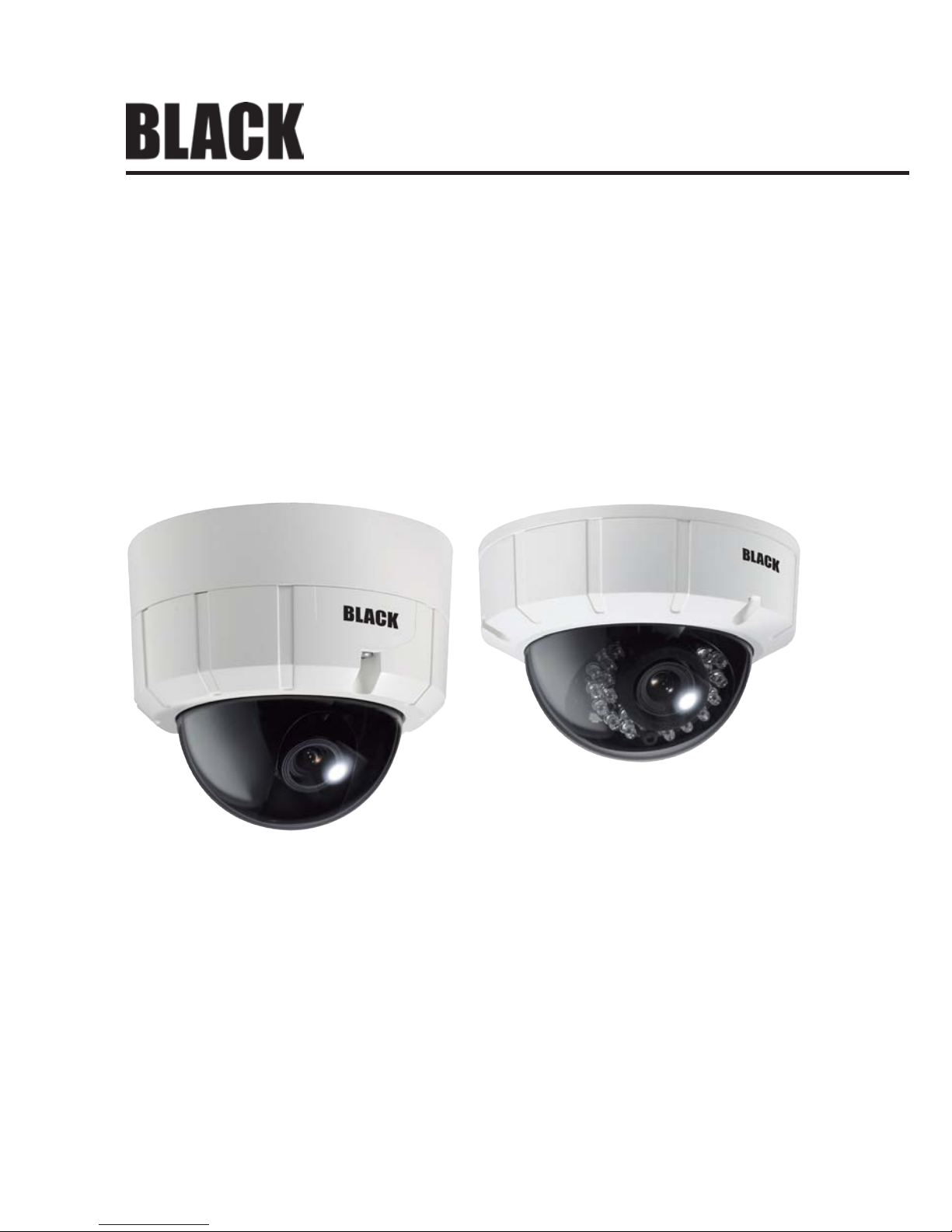
These high performance indoor/outdoor CCTV bullet cameras feature a very high resolution Sony® CCD sensor providing 600 TVL,
with a 2.8 – 11 mm lens, a digital wide dynamic range, dual voltage range support (24 Vac, 12 Vdc), and on-screen display (OSD) for
control and setup. These cameras are available with or without an IR array, and in either a durable plastic or vandalproof enclosure.
Features
• Wall or ceiling mounting through 3-axis camera bracket
• Safety strap keeps dome cover attached while making adjustments
• 1/3” Sony Super HAD CCD II: 410 K pixels
• High resolution 600 TV Lines
• Day or day/night operation (ICR)
• Vari-focal lens 2.8~11 mm
• Digital wide dynamic range
• Digital noise reduction
• Privacy mask function
• On screen display (OSD)
• Motion detection
• Parking line
• Backlight Compensation (BLC) and High Light Compensation (HLC)
• IR Smart features
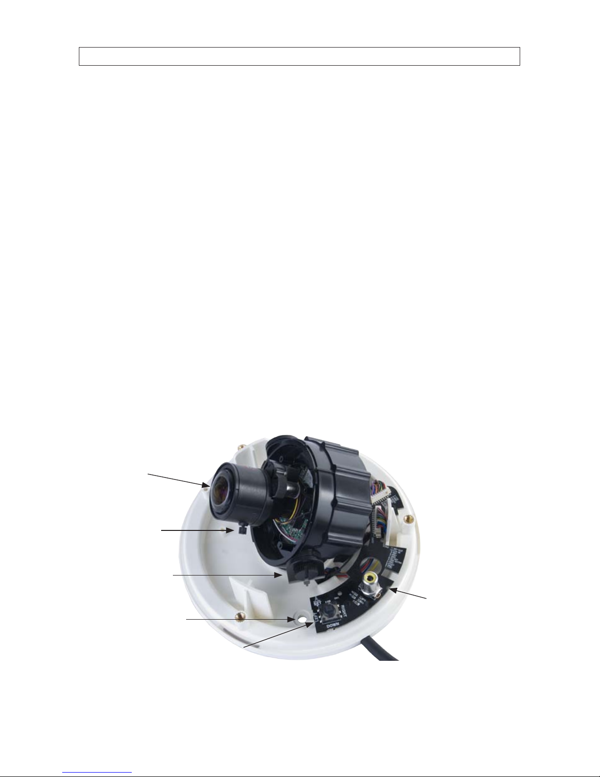
Joystick /
OSD Control
Focus / Zoom
controls
Lens
Video Out
monitor
port
Power / Video
drop cable
Gimbal
lock screw
Hole for
mounting
screw (4)
Internal Components - Cameras Without IR Array
2
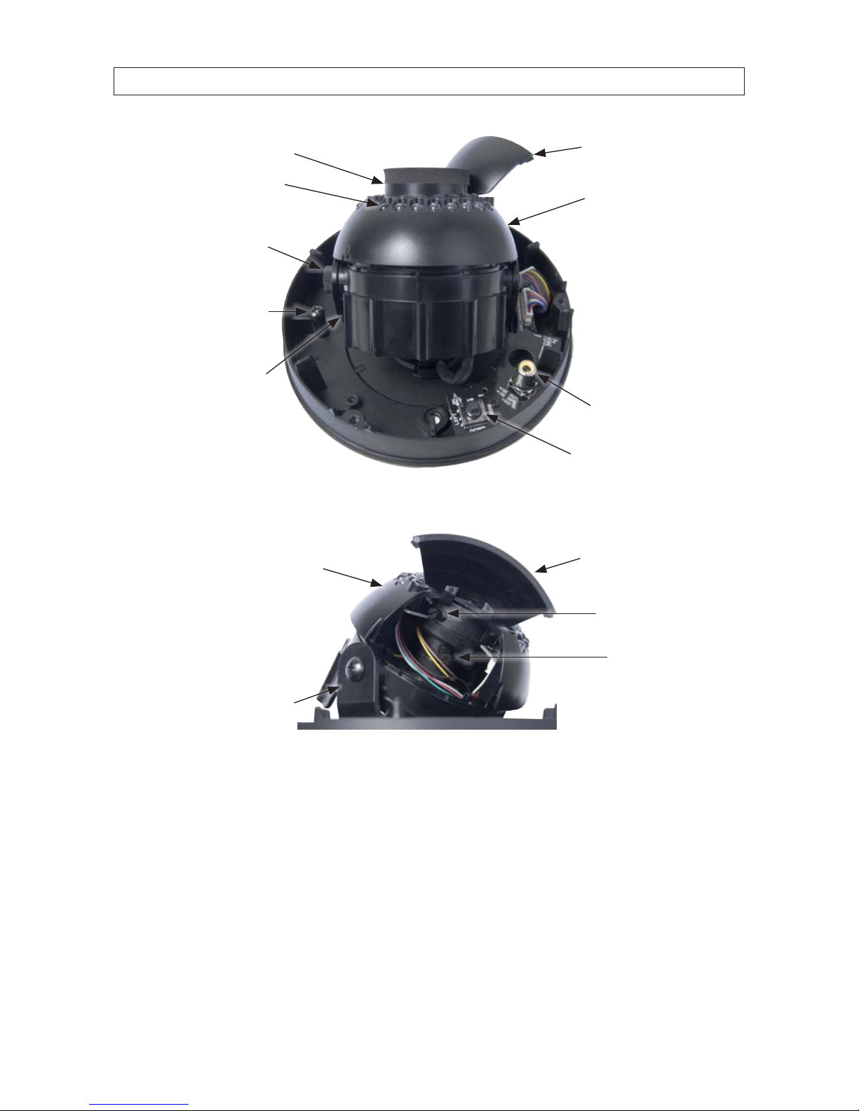
Joystick /
OSD Control
Lens Controls
Inside Housing
Lens Controls
Access Door
Lens
Assembly
Video Out
Tilt/Pan
Gimbal
Tilt Lock
Thumb Screw
Cover Strap
Anchor Point
IR Array
Internal Components - Cameras With IR
Far (L) – Near (R)
Control
Tele (L) – Wide (R)
Control
Lens Controls
Access Door
Lens
Housing
Tilt/Pan
Gimbal
Lens Controls - Cameras with IR
1.1 Cameras with a vandalproof enclosure
Vandalproof cameras are IP67 rated and include a rugged die-cast aluminum enclosure. They are ush surface mountable using the
mount adaptor box supplied.
SECTION 1: INTRODUCTION
3High Performance CCTV Dome Camera User Manual
SECTION 1: INTRODUCTION
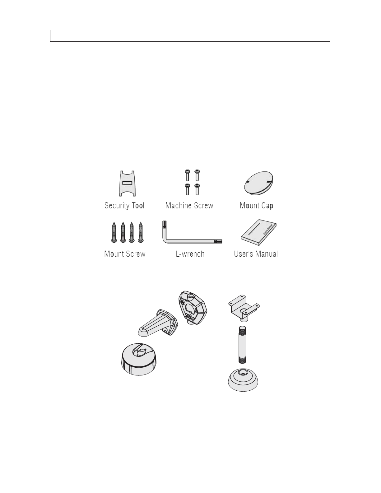
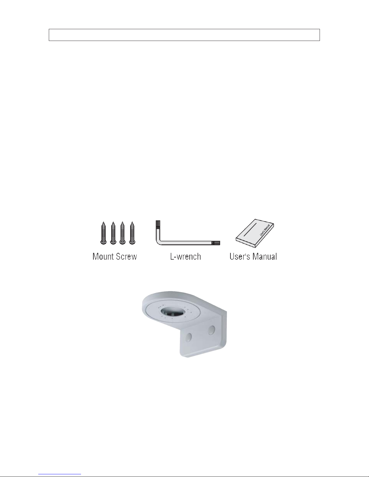
1.1.1 What’s in the box
Your camera includes the following:
• Security tool
• Machine screws (4)
• Mounting cap
• Mounting screws (4)
• L-wrench
• User manual
• Dome bracket (optional)
What’s in the box
Optional dome bracket for wall and ceiling mounting
4
SECTION 1: INTRODUCTION
1.1.2 What you need
To install the camera you will need:
• 12 Vdc or 24 Vac power source
• Tools for mounting the camera
1.2 Cameras with a plastic enclosure
1.2.1 What’s in the box
Your camera includes the following:
• Mounting screws (4)
• L-wrench
• User manual
• Dome bracket (optional)
What’s in the box
Optional dome bracket

5High Performance CCTV Dome Camera User Manual
SECTION 2: INSTALLATION
SECTION 2
Installation
2.1 General Guidelines
• Outdoor installations: Ensure the cover is secured to the dome base with the machine screws provided and rubber seals.
Dome cover
Rubber seal
Machine screw
Dome base
• Dome/window care: Handle the dome carefully to prevent scratching. If a scratch appears over the lens, adjust the dome
window to move the scratch away from the lens.
CAUTION
Keep dome cover and camera lens clean. To avoid smearing, do not expose the camera lens to a strong light source such as the
sun or spot lights.
• Monitor impedance: Set the monitor impedance switch to 75 Ω.
• Power supply: To avoid re or shock hazard, use only a UL listed power supply.
• Camera drop cable: The camera drop cable includes two connectors:
— Power connector (black with green terminal adapter) – The connector is non-polarized. Use 24 Vac power source
(AC24V 1A adapter) or 12 Vdc power source (DC12V 1A adapter).
— Video coax connector (BNC, yellow) – for transmission of the video signal across coax (75 Ω) cable.

6
SECTION 2: INSTALLATION
Power Connector
Video Coax
Connector
2.1.1 What you need
To install the camera you will need:
• 12 Vdc or 24 Vac power source
• Tools for mounting the camera
2.2 Vandalproof camera
mounting
The camera can be installed on a junction box or directly to a wall
or ceiling.
1. Attach the surface mount bracket to the ceiling or wall
using four (4) mounting screws.
2. Connect the dome base to the surface mount bracket using
the screws with rubber rings provided.
3. Route the power and video cables to the camera location
and attach them to the camera drop cable (see General
guidelines above).
4. Attach the dome base to the surface mount bracket using
the four machine screws provided.

7High Performance CCTV Dome Camera User Manual
SECTION 2: INSTALLATION
2.3 Plastic camera mounting
1. Connect the dome base to the mounting surface using four
(4) screws.
2. Route the power and video cables to the camera location
and attach them to the camera drop cable (see General
guidelines above).
2.4 Camera adjustments
1. Attach a video setup monitor to the yellow RCA (EXTRA VIDEO OUT) connector inside the camera assembly, or setup a
remote monitor for viewing video from the camera.
2. Power on the camera and video monitor.
3. While observing video from the camera, adjust the gimbal pan/tilt/horizon to aim the camera in the preferred direction.
Pan adjustment (rotate gimbal) Tilt adjustment

8
SECTION 2: INSTALLATION
Horizon adjustment
4. Adjust the image with the focus and zoom levers.
Focus adjustment
Zoom adjustment
5. Congure your camera using the software menus in the OSD. See Software Setup in the following section of this manual.
6. Place the dome cover over the base and adjust the dome window. Tighten the captive screws that secure the cover to the
base.
7. Clean the camera dome with an approved glass cleaning solution and a lint free cloth.
— Dust can be removed from the unit by wiping it with a soft damp cloth. To remove stains, gently rub the surface with
a soft cloth moistened with a mild detergent solution, then rinse and dry it with a soft cloth.

9High Performance CCTV Dome Camera User Manual
SECTION 2: INSTALLATION
— Remove all foreign particles, such as plastic or rubber materials, attached to the camera housing. These may cause
damage to the surface over time.
CAUTION
Do not use benzene, thinner or other chemical products on the camera assembly; these may dissolve the paint and
promote damage of the surfaces. Before using any chemical product, read the accompanying instructions carefully.

10
SECTION 3: SOFTWARE SETUP
SECTION 3
Software Setup
Use the SETUP joy stick on the OSD control panel to navigate through the menu system. Press the joy stick down (toward the PC
board) to enter the SETUP menu or select an entry, rock the stick up or down to highlight an item in the list, and left or right display
the option you want to select.
The SETUP menu consists of a list of sub-menus or displays the
option selected for a camera function. When sub-menus are
available, the
symbol is shown.
3.1 LENS
LENS: Select lens type: DC / VIDEO / MANUAL
3.2 EXPOSURE
SHUTTER: You can set the shutter to auto or manual mode. Options are: AUTO, 1/60 sec, FLK, 1/250 sec, 1/500 sec, 1/1000 sec,
1/2000 sec, 1/4000 sec, 1/5000 sec, 1/10000 sec, 1/100000 sec
BRIGHTNESS: You can adjust brightness level. 0 (dark) ~ 255 (bright) steps
AGC: You can select auto gain control level. OFF / LOW / MIDDLE / HIGH

11High Performance CCTV Dome Camera User Manual
SECTION 3: SOFTWARE SETUP
DWDR: The DWDR feature employs intelligent light level control to compensate for strong backlight conditions. DWDR: OFF / ON
DWDR OFF DWDR ON
3.3 WHITE BALANCE
WHITE BAL: You can select one of the following modes: ATW1 / ATW2 / AWC g SET / MANUAL (INDOOR / OUTDOOR / MANUAL)
— ATW1: Automatically adjusts color according to the available lighting for temperature range: 2500°K to 9500°K.
— ATW2: Automatically adjusts color according to the available lighting for temperature range: 2300°K to 10000°K.
— AWC g SET: It is a xed white balance mode that may be automatically readjusted only by pressing SET Button in
ONE PUSH mode.
— OUTDOOR: Set color temperature for Outdoor light (5400°K)
— INDOOR: Set color temperature for Indoor light (3200°K)
— MANUAL: Color can be corrected when the user increases or decreases “Red Gain” or “Blue Gain”.
— RED GAIN: Adjust R gain value 0 ~ 255
— BLUE GAIN: Adjust B gain value 0 ~ 255

12
SECTION 3: SOFTWARE SETUP
3.4 BACKLIGHT
BACKLIGHT: Select OFF / BLC / HLC
BLC (Back Light Compensation)
— AREA SEL: Select AREA1, AREA2
— AREA STATE: Select OFF / ON
— GAIN: Select 0 ~ 255 steps
— HEIGHT: Select 0 ~ 15 steps
— WIDTH: Select 0 ~ 15 steps
— LEFT/RIGHT: Select 0 ~ 15 steps
— TOP/BOTTOM: Select 0 ~ 15 steps
HLC (High Light Compensation)
— LEVEL: Select 0 ~ 255 steps
— MODE: ALL DAY, NIGHT ONLY

13High Performance CCTV Dome Camera User Manual
SECTION 3: SOFTWARE SETUP
3.5 DAY&NIGHT
DAY&NIGHT: Select AUTO / COLOR / B/W / EXT ·
AUTO: Day&Night Auto mode
— D -> N LEVEL: 182 ~ 192 steps
— D -> N DELAY: 1 ~ 30 SEC
— N -> D LEVEL: 0 ~ 10 steps
— N -> D DELAY: 1 ~ 30 SEC
COLOR: Day&Night only color mode
B/W: Day&Night black and white (B/W) mode
— BURST: OFF / ON
— IR SMART: OFF / ON. This option controls the IR LED output level to compensate for object distance. The IR SMART
option is used for objects in an area of the image.
IR SMART OFF IR SMART ON
R GAIN: 0 ~ 255
HEIGHT: 0 ~ 15

14
SECTION 3: SOFTWARE SETUP
WIDTH: 0 ~ 15
LEFT/RIGHT: 0 ~ 15
TOP/BOTTOM: 0 ~ 15
— IR LEVEL: HIGH / LOW
EXT: Day&Night EXT mode
3.6 DPC (Dead Pixel Compensation)
Select DPC for dead pixel compensation processing. DPC can be set to OFF (default) or AUTO. When AUTO is used, the camera will
remove defective pixels from an image automatically.
3.7 SPECIAL
CAM TITLE: Select camera title menu (Text edit).
MOTION: Select camera title menu (Text edit)
— AREA SEL: Select AREA1, AREA2, AREA3, AREA4

15High Performance CCTV Dome Camera User Manual
SECTION 3: SOFTWARE SETUP
— AREA STATE: Select OFF / ON
— HEIGHT: Select 0 ~ 15 steps
— WIDTH: Select 0 ~ 15 steps
— LEFT/RIGHT: Select 0 ~ 15 steps
— TOP/BOTTOM: Select 0 ~ 15 steps
— DEGREE: Select 0 ~ 255 steps
— VIEW: OFF / ON
PRIVACY: You can cover an area of the screen.
— AREA SEL: Select AREA1, AREA2, AREA3, AREA4
— AREA STATE: Select OFF / ON
— HEIGHT: Select 0 ~ 255 steps
— WIDTH: Select 0 ~ 255 steps
— LEFT/RIGHT: Select 0 ~ 255 steps
— TOP/BOTTOM: Select 0 ~ 255 steps
— COLOR: Select 0 ~ 15 steps
PARK.LINE: You can insert a line on the screen. This feature may be useful when aligning the camera image with objects in the
eld of view.
— LT: You can adjust the top left area on screen. (0 ~ 195 steps)
— LB: You can adjust the bottom left area on screen. (0 ~ 194 steps)
— RT: You can adjust the top right area on screen. (0 ~ 194 steps)
— RB: You can adjust the bottom right area on screen. (0 ~ 194 steps)
— F: You can adjust the front area on screen. (0 ~ 68 steps)
— N: You can adjust the near area on screen. (0 ~ 68 steps)
— T: You can adjust the parking line thickness. (0 ~ 15 steps)

16
SECTION 3: SOFTWARE SETUP
IMAGE ADJ.: You can adjust camera image.
— LENS SHAD: LEVEL: 0 ~ 255 steps
— 2DNR: (on-screen Digital Noise Reduction) (OFF/ON)
— MIRROR: (reverse the camera image horizontally) (OFF/ON)
MIRROR OFF MIRROR ON
— FONT COLOR:
FONT: 16 colors (O ~ 15 steps)
ID & TITLE: O ~ 15 steps
— CONTRAST: You can adjust contrast on screen. (0 ~ 255 steps)
— SHARPNESS: You can adjust camera image for clarity. (0 ~ 31 steps)
— DISPLAY: You can adjust camera output for the display type. (CRT / LCD / USER)
CRT (Cathode Ray Tube, Braun tube). PED LEVEL: 0 ~ 63 steps, COLOR GAIN: 0 ~ 255 steps
LCD (Liquid Crystal Display)
GAMMA: 0.05 ~ 1.00 steps
PED LEVEL: 0 ~ 63 steps
COLOR GAIN: 0 ~ 255 steps
USER
GAMMA: 0.05 ~ 1.00 steps

17High Performance CCTV Dome Camera User Manual
SECTION 3: SOFTWARE SETUP
PED LEVEL: 0 ~ 63 steps
COLOR GAIN: 0 ~ 255 steps
— NEG.IMAGE: You can invert a color image, or a black and white image. (OFF/ON)
COMM ADJ.:
— CAM ID: Select the camera ID. 1 ~ 255
— BAUD RATE: Select serial communication speed: 2400 / 4800 / 9600 / 19200 / 38400 / 57600 bps
— PROTOCOL: Select operating protocol. PELCO-D / PELCO-P
— DISPLAY ID: Select display item. OFF/ON
— ID POS: You can adjust ID position on screen.
LANGUAGE: You can select language. ENGLISH / CHINESE
VERSION: Factory vision.
RESET: Set the camera options to the factory default settings.

18
SECTION 4: SPECIFICATIONS
SECTION 4
Specications
Table 1. Model Dierences
Indoor Outdoor TDN IR
BLK-CCD203VS2 BLK-CCD22 3VS2 -- --
BLK-CCD205VH2 BLK-CCD22 5VH2 √ - -
BLK-CPD206VH2 BLK-CPD226VH2 √ √
TDN: True Day & Night, uses an IR cut lter instead of switching the image to black and white.
IR: Built-in infrared LED array
Table 2. Component Specications
Compo nent Value
Image Sensor 1/3" SONY Super HAD CCD II
Total Pixels 811(H) × 508(V)
Scanning system 2:1 interlace
Scanning frequency 15.734 KHz(H), 59.94 Hz( V)
Sync system Internal
Resolution Max 60 0 TV lines in color, 650 TV lines in B/ W
Min. Illumination Color: 0.3 lux , BW: 0.1 lux (0 lux with IR L ED on)
Video output 1.0 Vp-p (75 ohm, composite)
S/N ratio > 50 dB (AGC o )
Exposure Shutter / Brightness / AGC / DWDR
Lens DC / VIDEO / MANUAL
Gain control O / Low / Middle / High
Shutter speed 1/60 ~ 1/100,000 se c
DWDR O / On (0 ~ 35 steps)
Flicker less O / On
Brightness 0 ~ 255 steps
White balance ATW1 / ATW2 / AWC / Outdoor / Indoor / Manual
BLC O / BLC / HLC
BLC Area / gain s electable

19High Performance CCTV Dome Camera User Manual
SECTION 4: SPECIFICATIONS
Compo nent Value
HLC All Day / Night / (0~255 steps)
Day&Night Au to / Color / BW / Ex t
Auto Level / De lay selectable
BW Burst o/on / IR Smar t o/on (Gain/level selectable)
DPC Dead Pixels Compensation
Special Title / MD / PM / Parking / Image / Comm / Language / Version
Cam Tit le Text edit
Motion O / On (4 position)
Privacy O / On (8 position)
Park. L ine O / On (var iable size)
Language English / Chinese
Image ADJ Lens Shad / DNR / Mirror / Font co lor / Contrast / Sharpness / Display / Neg. Image
Lens Shading O / On (0~255 steps)
DNR O / On
Mirror O /On
Font Color ID & Title / OSD font color se lectable
Contrast 0~255 steps
Sharpn ess 0~31 steps
Display CRT / LCD / User
Negative Image O / On
Power Sou rce AC24V / DC12V
Power Consumption 100 mA
Power Input Connector
Video O utput Connector
Operating Temperature +14 °F ~ +122 °F (-10 °C ~ +50 °C)
Operating Humidity 0 ~ 86 % (non-condensing)
Storage Temperature - 4 °F ~ +140 ° F (-20 °C ~ + 60 °C)

20
APPENDIX A: TROUBLESHOOTING
APPENDIX A
Troubleshooting
Problem Solution
Nothin g appears on the s creen. - Check the power connec tions.
- Check the video cable connections.
- Ensure t hat the lens mode is set to DC (VIDEO).
The video image is not clear. - Clean the lens with a s oft, clean cloth.
- Adjust t he monitor screen for room lighting conditions.
- Move the c amera if necessary.
The screen is dark. - Adjust t he contrast f eature of the monitor.
- If you have an intermediate device, set the 75Ω /Hi-Z prop erly, and check the terminals.
The MOTION DETECT ION function is not working - Is “MOTION DETECTION” mode turned on?
- Is the MD Sensitivit y set too low? Increase the sensitivity.
- Check the setting of the MD AREA.
The WDR f unction is not working - Is the WDR level too low?
- Is the AE Mode set to MANUAL? WDR is disabled in MANUAL exposure mode.
Colors are not quite right. - Is the c amera facing directly into sunlight or u orescent light?
- Is the auto iris lens is being used?
- Check the connection of the lens connector cable.
The Day&Night function doesn’t work. - Is the AGC (EXPOSURE menu) set to OFF? The Auto Day&Night Func tion doesn’t wo rk if the AGC is OFF.

21High Performance CCTV Dome Camera User Manual
APPENDIX B: CAMERA DIMENSIONS
APPENDIX B
Camera Dimensions
Camera with vandalproof housing
4.96"
2.95"
1.38"
2.95"
1.61"
Camera with plastic housing
2.09"
3.29"
1.75"
1.52"
1.81"
 Loading...