

NVR4020, NVR8040
Embedded Network Video Recorder
User Manual
Products: NVR4020, NVR8040
NVR4020, NVR8040
PLEASE READ THIS MANUAL BEFORE USING YOUR SYSTEM, and always follow the instructions for safety
and proper use. Save this manual for future reference.
NVR4020-8040_SM
9/19/2013
ii
CAUTION
Do not expose this appliance to rain or moisture. Operate this device only in environments where the temperature or
humidity is within the recommended range. Operation at extreme temperatures or in very high or low humidity levels
may cause electric shock and shorten the life of the product.
CAUTION
FCC Caution: To assure continued compliance, use only shielded interface cables when connecting to computer or
peripheral devices. Any changes or modications not expressly approved by the party responsible for compliance could
void the user’s authority to operate this equipment.
NOTE
This equipment has been tested and found to comply with the limits for a Class “A” digital device, pursuant to Part 15
of the FCC Rules. These limits are designed to provide reasonable protection against harmful interference when the
equipment is operated in a commercial environment. This equipment generates, uses, and can radiate radio frequency
energy and, if not installed and used in accordance with the instruction manual, may cause harmful interference to radio
communications.
LEGAL NOTICE
Observint Technologies (Observint) products are designed to meet safety and performance standards with the use of
specic Observint authorized accessories. Observint disclaims liability associated with the use of non-Observint
authorized accessories.
The recording, transmission, or broadcast of any person’s voice without their consent or a court order is strictly
prohibited by law.
Observint makes no representations concerning the legality of certain product applications such as the making,
transmission, or recording of video and/or audio signals of others without their knowledge and/or consent. We
encourage you to check and comply with all applicable local, state, and federal laws and regulations before
engaging in any form of surveillance or any transmission of radio frequencies.
Microsoft, Windows, and Internet Explorer are either registered trademarks or trademarks of Microsoft Corporation in
the United States and/or other countries. Android is a trademark of Google Inc. Use of this trademark is subject to
Google Permissions. Apple, iPhone, iPod touch, and iPad are registered trademarks of Apple Inc.
Other trademarks and trade names may be used in this document to refer to either the entities claiming the marks
and names or their products. Observint disclaims any proprietary interest in trademarks and trade names other than
its own.
No part of this document may be reproduced or distributed in any form or by any means without the express written
permission of Observint, Inc.
© 2013 by Observint Technologies. All Rights Reserved.
11000 N. Mopac Expressway, Building 300, Austin, TX 78759
For Sales and Support, contact your distributor.

iii
NVR4020, NVR8040 Embedded NVR User Manual
SAFETY INSTRUCTIONS
Regulatory information
FCC information
FCC compliance: This equipment has been tested and found to comply with the limits for a digital device, pursuant to part 15 of the
FCC Rules. These limits are designed to provide reasonable protection against harmful interference when the equipment is operated
in a commercial environment. This equipment generates, uses, and can radiate radio frequency energy and, if not installed and used
in accordance with the instruction manual, may cause harmful interference to radio communications. Operation of this equipment
in a residential area is likely to cause harmful interference in which case the user will be required to correct the interference at his
own expense.
FCC conditions
This device complies with part 15 of the FCC Rules. Operation is subject to the following two conditions:
1. This device may not cause harmful interference.
2. This device must accept any interference received, including interference that may cause undesired operation.
Preventive and Cautionary Tips
Before connecting and operating your device, please be advised of the following tips:
• Ensure unit is installed in a well-ventilated, dust-free environment.
• Unit is designed for indoor use only.
• Keep all liquids away from the device.
• Ensure environmental conditions meet factory specications.
• Ensure unit is properly secured to a rack or shelf. Major shocks or jolts to the unit as a result of dropping it may cause damage
to the sensitive electronics within the unit.
• Use the device in conjunction with an UPS if possible.
• Power down the unit before connecting and disconnecting accessories and peripherals.
• A factory recommended HDD should be used for this device.
• Improper use or replacement of the battery may result in hazard of explosion. Replace with the same or equivalent type only.
Dispose of used batteries according to the instructions provided by the battery manufacturer.
Safety Instructions
Read these instructions and keep them in a safe place for future reference.
• Please refer all work related to the installation of this product to qualied service personnel or system installers.
• Do not operate the appliance beyond its specied temperature, humidity or power source ratings.
• Place the unit on a at surface not prone to vibration or impact.
• Use the appliance at temperatures between 14 °F ~ 131 °F (-10 °C ~ +55 °C) and relative humidity below 90%. The input
power source for this appliance is between 90 ~ 264 Vac, 47 ~ 63 Hz.

iv
• Install the unit away from heat sources such as radiators, heat registers and stoves.
• Installation of the unit near consumer electronics devices, such as stereo receiver/ampliers and televisions, is permitted as
long as the air surrounding the terminal does not exceed the above mentioned temperature range.
• Handle hard disk drives with care.
— It is possible to damage hard drives if they are moved while their motors are still running. To allow the hard drive to spin
down and park its heads, wait at least 10 seconds after disconnecting power before moving the unit.
— To avoid shock and vibration damage to the internal hard drive, do not move the unit while it is plugged in.
— Protect hard disk drives from static electricity.
— Do not stack hard disk drives or keep them upright.
— Do not use an electric or magnetic screwdriver to install hard disk drives.
• Do not place the unit in an enclosed area where the cooling vents are blocked or impede the ow of air through the ventilation
openings.
• Protect the power cord from being stepped on or pinched particularly at plugs and the points where they exit from the
apparatus.
• Do not drop metallic parts through slots. This could permanently damage the appliance. Turn the power o immediately and
contact qualied service personnel for service.
• Handle the appliance with care. Do not drop or shake, as this may damage the device.
• Do not expose the appliance to water or moisture, nor try to operate it in wet areas. Do not install the unit in an area where
condensation occurs. Do not operate with wet hands. Take immediate action if the appliance becomes wet. Turn the power o
and refer servicing to qualied service personnel. Moisture may damage the appliance and also cause electric shock.
• Do not use strong or abrasive detergents when cleaning the surfaces of this product. When dirt is hard to remove, use a mild
detergent and wipe gently.
• Do not overload outlets and extension cords. Electric shock or re may result.
• Save your system conguration.
• Distributing, copying, disassembling, reverse compiling, reverse engineering, and exporting, in violation of export laws, the
software provided with this product is expressly prohibited.

v
NVR4020, NVR8040 Embedded NVR User Manual
TABLE OF CONTENTS
Table of Contents
SECTION 1 Systems Overview ................................................................... 1
1.1 NVR Controls, connectors and indicators .................................................3
1.1.1 Remote control ..................................................................4
1.1.2 Mouse control ...................................................................5
1.1.3 Soft keyboard ...................................................................6
SECTION 2 Installing the System ................................................................7
2.1 Getting Started: Unpacking the Equipment ..............................................7
2.2 NVR installation general guidelines .....................................................7
2.2.1 Placement ......................................................................7
2.3 Install the NVR and monitor ...........................................................8
2.4 Camera installation ..................................................................9
2.4.1 General Guidelines ...............................................................9
2.4.2 Install cameras .................................................................10
2.5 Connecting it together – initial system setup ...........................................11
2.5.1 Using the Wizard for basic conguration setup ......................................11
2.6 Using the Menu system ..............................................................17
2.6.1 Using the Camera menu .........................................................17
2.7 Conguring HDD settings ............................................................18
2.7.1 Checking HDD status ............................................................18
2.7.2 Managing Network HDD .........................................................19
2.7.3 Conguring the HDD ............................................................21
2.7.4 Conguring HDD Quota mode ....................................................21
2.7.5 HDD Detect ....................................................................23
2.8 Conguring Exception Alarms .........................................................25
SECTION 3 Startup, Shutdown, Reboot. . . . . . . . . . . . . . . . . . . . . . . . . . . . . . . . . . . . . . . . . . . . . . . . . . . . . . . . . . 27
3.1 Starting Up, Shutting Down and Rebooting the NVR ......................................27
3.1.1 Startup .......................................................................27
3.1.2 Shutdown .....................................................................27
3.1.3 Rebooting the NVR .............................................................28
SECTION 4 Live View Interface ................................................................. 29
4.1 Quick Setting Toolbar ................................................................30
4.2 Live View pop-up menu ..............................................................31
4.2.1 Live View settings ..............................................................32

vi
TABLE OF CONTENTS
SECTION 5 Record, Playback and Video Backup ...................................................34
5.1 Conguring record settings ...........................................................35
5.1.1 Setting camera encoding parameters ..............................................35
5.1.2 Conguring Record schedule .....................................................36
5.1.3 Conguring Motion Detection Recording ...........................................39
5.1.4 Manual record .................................................................43
5.1.5 Conguring Holiday recording ....................................................44
5.1.6 Conguring HDD Group for Recording ..............................................45
5.1.7 Files Protection .................................................................46
5.2 Playback ...........................................................................47
5.2.1 Playing back video by channel ....................................................47
5.2.2 Playing back a motion event .....................................................51
5.2.3 Playback by Tag ................................................................54
5.2.4 Playback from System Logs ......................................................58
5.2.5 Auxiliary Functions - Playback frame by frame ......................................61
5.2.6 Auxiliary Functions - Reverse Playback of Multi-channel ..............................61
5.2.7 Digital Zoom ...................................................................62
5.3 Backing up Record Files - Export .......................................................63
5.3.1 Quick Export ...................................................................63
5.3.2 Export by video search ..........................................................65
5.3.3 Export by Event Search ..........................................................67
5.3.4 Exporting Video Clips during playback .............................................71
SECTION 6 Managing User Accounts ............................................................75
6.1 Adding a user account ...............................................................75
6.2 Deleting a user account ..............................................................78
6.3 Editing a user account ...............................................................78
SECTION 7 Network Settings ..................................................................80
7.1 Conguring General Settings .........................................................80
7.2 Conguring Advanced Settings ........................................................80
7.2.1 Conguring PPPoE Settings ......................................................80
7.2.2 Conguring DDNS ..............................................................81
7.2.3 Conguring NTP Server ..........................................................83
7.2.4 Conguring SNMP ..............................................................83
7.2.5 Conguring Remote Alarm Host ..................................................84
7.2.6 Conguring Multicast ...........................................................84

vii
NVR4020, NVR8040 Embedded NVR User Manual
TABLE OF CONTENTS
7.2.7 Conguring RTSP ...............................................................85
7.2.8 Conguring Server and HTTP Ports ................................................86
7.2.9 Conguring Email ..............................................................86
7.2.10 Conguring UPnP™ .............................................................88
SECTION 8 System Maintenance ...............................................................89
8.1 System Information .................................................................89
8.2 Log Information ....................................................................89
8.2.1 Log Search. . . . . . . . . . . . . . . . . . . . . . . . . . . . . . . . . . . . . . . . . . . . . . . . . . . . . . . . . . . . . . . . . . . . .90
8.2.2 Log Export .....................................................................92
8.3 Import / Export system conguration ..................................................94
8.4 Upgrade Firmware ..................................................................96
8.5 Default ............................................................................98
8.6 Net Detect .........................................................................98
8.6.1 Checking Network Trac ........................................................98
8.6.2 Testing Network Delay and Packet Loss ............................................99
8.6.3 Exporting Network Packet .......................................................99
8.6.4 Checking the network status ....................................................100
8.6.5 Checking Network Statistics .....................................................101
SECTION 9 Remote Access ....................................................................102
9.1 Remote login ......................................................................102
9.2 Remote Live View screen ............................................................104
9.3 Remote Playback screen ............................................................105
9.4 Remote Log screen .................................................................107
9.5 Remote Conguration screen ........................................................107
SECTION 10 Cleaning .........................................................................109
APPENDIX A Glossary .........................................................................110
APPENDIX B FAQ .............................................................................111
APPENDIX C Adding Cameras on the LAN to the NVR. . . . . . . . . . . . . . . . . . . . . . . . . . . . . . . . . . . . . . . . . . . . . . . 112
C.1 Editing camera options .............................................................114
C.2 Conguring customized protocols ....................................................115

viii
NOTES

1
NVR4020, NVR8040 Embedded NVR User Manual
SECTION 1: SYSTEM OVERVIEW
SECTION 1
Systems Overview
Congratulations on purchasing your new Embedded NVR security system! Your system includes the following key features:
General
• Each channel supports dual-stream video.
• Up to 8 network cameras with the NVR8040, 4 network cameras with the NVR4020.
• Independent conguration for each channel including resolution, frame rate, bit rate, image quality, etc.
• The quality of the input and output record is congurable.
Local Monitoring
• Simultaneous HDMI and VGA monitor output with resolutions up to 1920 x 1080.
• Multiple screen display in live view is supported; the display sequence of channels is congurable.
• Congurable Live View display of groups and tours.
• Live view Quick setting menu.
• Motion detection, tamper-proof, video exception alert and video loss alert functions.
• Privacy mask.
• Zooming in by clicking the mouse and PTZ tracing by dragging mouse.
HDD Management
• Supports up to 2 internal SATA hard disk drives, with a maximum of 4TB storage capacity in each drive.
• 8 network disks (8 NAS disks, or 7 NAS disks+1 IP SAN disk) can be connected.
• Supports HDD S.M.A.R.T. and bad sector detection.
• Supports HDD group management.
• Supports HDD standby function.
• Supports HDD property: redundancy, read/write (R/W).
• Supports HDD quota management; a dierent capacity can be assigned to each camera channel.
Recording and Playback
• Holiday recording schedule conguration.
• Normal and event video encoding parameters.
• Multiple recording types: manual, normal or motion
• Eight recording time periods with separated recording types.
• Supports pre-record and post-record for motion detection recording, and pre-record time for schedule and manual recording.
• Tag marker insertions, search and playback by tags.
• Lock/unlocking video les.
• Searching and playing back record les by channel number, recording type, start time, end time, etc.

2
• Motion analysis for the selected area in the video.
• Zoom in/out during playback.
• Forward/reverse, fast/slow playback.
• Forward/reverse multi-channel playback.
• Supports pause, skip forward and skip backward during playback.
• Up to 8-channel synchronous playback at 4CIF real time (NVR8040) or 4-channel synchronous playback (NVR4020).
Backup
• Export video data to USB device.
• Export video clips during playback.
• Management and maintenance of backup devices.
Alarm and Exception
• Alarm of for video loss, motion detection, tampering, illegal login, IP coniction, network disconnected, abnormal record,
HDD error, HDD full.
Other Local Functions
• Operable by mouse or remote control.
• Three-level user management; admin user can create accounts and dene their operating permissions, including access to
camera channel.
• Operation, alarm, exceptions and log recording and search.
• Clear audible of alarms.
• Export and import NVR conguration.
Network Functions
• Self-adaptive 10M/100M/1000M network interface with multi-address, load balance, network fault tolerance, etc.
• Eight independent PoE network interfaces provided for NVR8040, four PoE network interfaces provided for NVR4020.
• Supports TCP/IP, PPPoE, DHCP, DNS, DDNS, NTP, SADP, SMTP, SNMP, NFS, and iSCSI protocols.
• Supports TCP, UDP and RTP for unicast.
• Auto/manual port mapping by UPnP.
• Remote reverse playback through RTSP.
• Remote search, playback, download, locking and unlocking of the record les.
• Remote parameters setup; remote import/export of device parameters.
• Remote viewing of the device status, system logs and alarm status.
• Remote keyboard operation.
• Remote locking and unlocking of control panel and mouse.
• Remote HDD formatting and rmware upgrade.
• Remote system restart and shutdown.
SECTION 1: SYSTEM OVERVIEW
3
NVR4020, NVR8040 Embedded NVR User Manual
SECTION 1: SYSTEM OVERVIEW
• Alarm and exception information can be sent to the remote host.
• Remotely start/stop recording.
• Remote capture.
• Embedded web server.
1.1 NVR Controls, connectors and indicators
Your new security system is easy to use and easy to setup. This section includes the function and use of the components included
with a NVR system. For installation instructions, refer to Section 2. Advanced control and conguration procedures are included in
Sections 3 through 9.
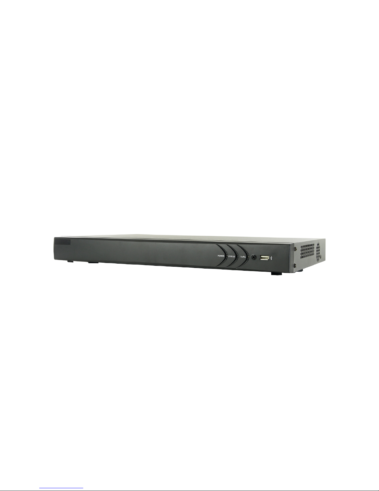
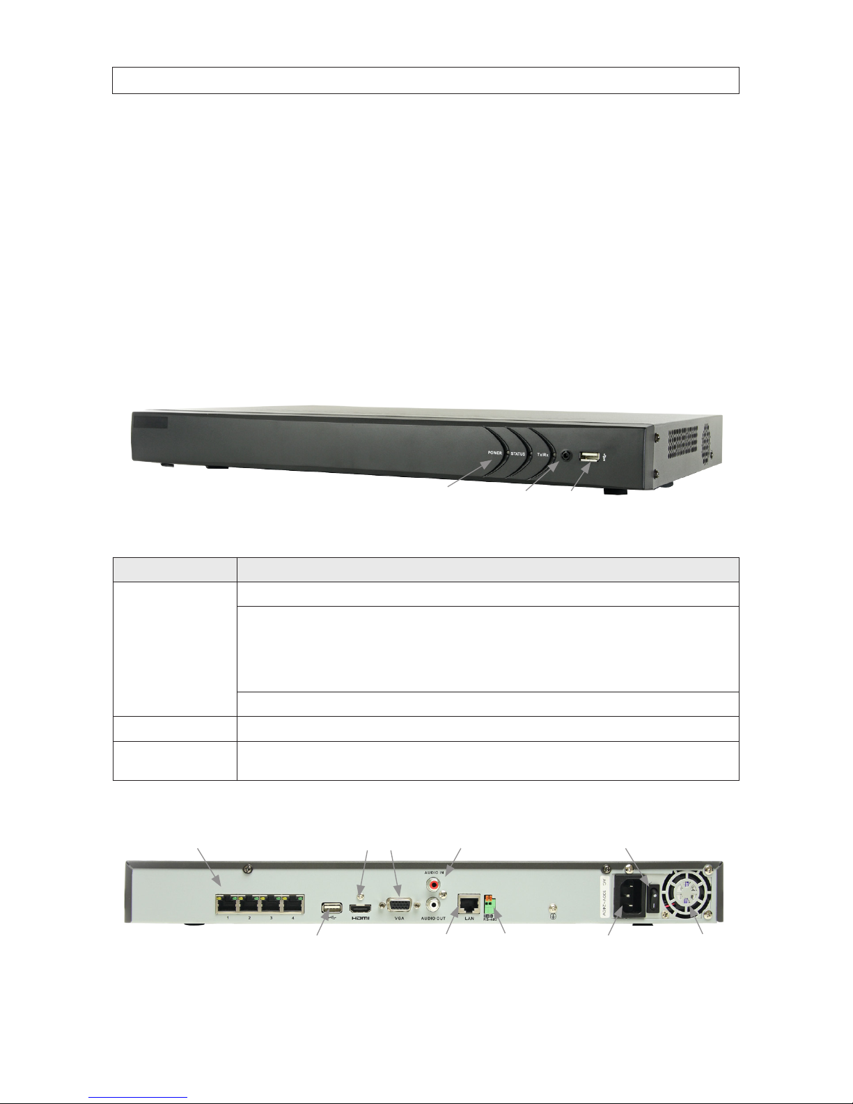
NVR Front Panel
IR Sensor
LED Indicators|
USB port
NVR8040, NVR4020 front panel
Item Usage
LED indicators Power: The POWER indicator turns green when NVR is powered on.
Status:
1. The light is green when the IR remote control is enabled
2. The light is r ed when the function of the composite keys (SHIFT) ar e used
3. The light is o ut when none of th e above condition is met
Tx/ Rx: TX/RX indicator ickers green when the network connection is f unctioning normally.
Infrared Sensor Sensor for the remote control.
USB por t
This port can be used for a por table mobile HDD, ash dr ive, DVD burner, or mouse. An additional USB por t is located o n the
back panel.
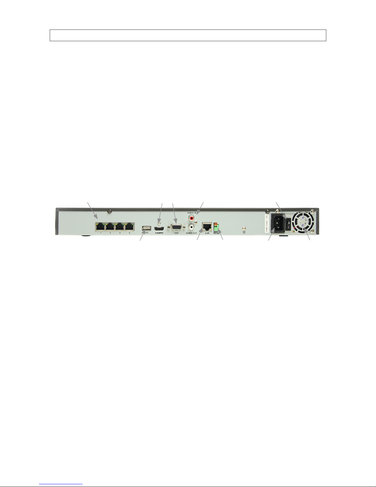
NVR Backpanel
Camera (CH1 - CH4)
LAN RS-485 Power connector Fan outlet
ON / OFF switchMonitor Out (HDMI, VGA)
Audio IN / OUT
USB
NVR4020 backpanel

4
NVR8040 backpanel
Item Description
Camera (CH1 - CH4) Network interface for IP c ameras solely dedicated to the NVR. These cameras can only b e accessed through the NVR. Each por t
provid es Power over Ethernet (PoE) power to the dev ice connecte d to it. NOTE: Only the Obser vint line of 3SVision cameras can
be att ached to thes e channels.
Monito r Out (HDMI, VGA) HDMI and DB9 (VGA) connector for monitor.
AUDIO IN / OU T Not fun ctional. Inc luded for future ex pansion.
ON / OFF switch Switch for power ing the NVR on and o
USB This port can be used for a por table mobile HDD, ash dr ive, DVD burner, or mouse. An additional USB por t is located o n the
front panel.
RS-485 terminations Not functional. Included for fut ure expansion.
Power connector Connec tor for standard 3-prong power cable.
1.1.1 Remote control
The enter key on the remote control or the front panel has the same function as a mouse left click. The IR Range of the remote
control is 10 meters. The buttons on the remote control correspond with the buttons on the front panel.
23
18
9177 5
6 4
11141518 16
1213 10
Item Name Function
1 POWER Power on/o the device.
2 DEV Enables/Disables Remote Control.
3 Alphanumeric Buttons Use for entering numerical data
4 EDIT Button Delete charac ters before curs or, che ck the checkbox and select the ON/OFF switch, start/stop record
clipping in playback
SECTION 1: SYSTEM OVERVIEW

5
NVR4020, NVR8040 Embedded NVR User Manual
SECTION 1: SYSTEM OVERVIEW
Item Name Function
5 A Button Adjust focus in the PTZ Control menu, also used to s witch between input methods (upper and lowercase
alphabet, symbols and numeric input).
6 REC Button Open the manual record interface
7 PLAY Button Playback, for direc t access to playback inter face.
8 INFO Button Reserved.
9 VOIP/MON button Switch betwe en main and spot output. In PTZ Control mo de, it is used to zoom out th e image.
10 MENU button Press t he button will help you re turn to the Main m enu (after succe ssful login).
Press and hold the button for 5 s econds to turn o audible key beep.
In PTZ Control mo de, the MENU/WIPER but ton will star t wiper (if applicable).
11 PREV button Switch betwe en single screen and multi-sc reen mode.
In PTZ Control mo de, it is used to adjust th e focus in conjun ction with t he A/FOCUS+ butto n.
12 DIRECTION/ENTER buttons DIRECTION: These bu ttons are use d to navigate bet ween dierent elds and items in menus.
In the Play back mode, the Up and Down buttons are us ed to speed up an d slow down recorded vid eo. The
Left and Right button sele ct the next and previous re cord les.
In Live View mode, these b uttons can be used to cycle t hrough channels.
In PTZ control mo de, they can cont rol the movement of the PT Z camera.
ENTER : The ENTER but ton is used to conrm se lection in any of the menu modes .
It can als o be used to tick check box elds.
In Playback mode, it can be u sed to play or pause the video.
In single -frame Playb ack mode, pressing the button will ad vance the video by a single f rame.
In Auto-switch mode, i t can be used to stop /start auto switch.
13 PTZ button Enter the PTZ Control mode (if applicable).
In the PTZ Contro l mode, it is used to adjus t the iris of the PT Z camera.
14 ESC button Re turn to the previous menu.
Press f or Arming/disarming the device in Live View mode.
15 RESERVED Reser ved for future usage.
16 F1 button Selec t all items on the list when used in a list eld.
In PTZ Control mo de, it will turn on/o PTZ light (if applicable).
In Playback mode, it is use d to switch bet ween play and reverse p lay.
17 PTZ Control buttons Buttons to adjust the iris, focus and zoom of a PT Z camera.
18 F2 button Cycle through tab pages.
In sync hronous playback mode, use to switch betwe en channels.
1.1.2 Mouse control
A standard 3-button (left/right/scroll-wheel) USB mouse can also be used with this NVR. To use a USB mouse:
1. Plug USB mouse into the either the front panel or backpanel USB connector of the NVR.
6
2. The mouse will be automatically detected. If the mouse is not detected, the mouse may not be compatible with the NVR.
Please refer to the recommended device list from your provider.
The operation of the mouse:
Action Eect
Right click
Live view: Show menu.
Menu: Exit cur rent menu to upper level menu.
Left click
Single click: Live view: Select channel an d show the quick set menu.
Menu: Select and enter.
Double click: Live view: Switch bet ween single-scre en and multi-screen.
Click and drag: PTZ control: pan, tilt and zoom.
Tamper-pro of, privacy mask and motion detection: Sele ct target area.
Digital zoom-in: Drag and select target area.
Live view: Drag channel/time bar
Scroll wheel
Scro ll up: Live view: Previous screen.
Menu: Previous item.
Scro ll down: Live view: Next screen.
Menu: Ne xt item.
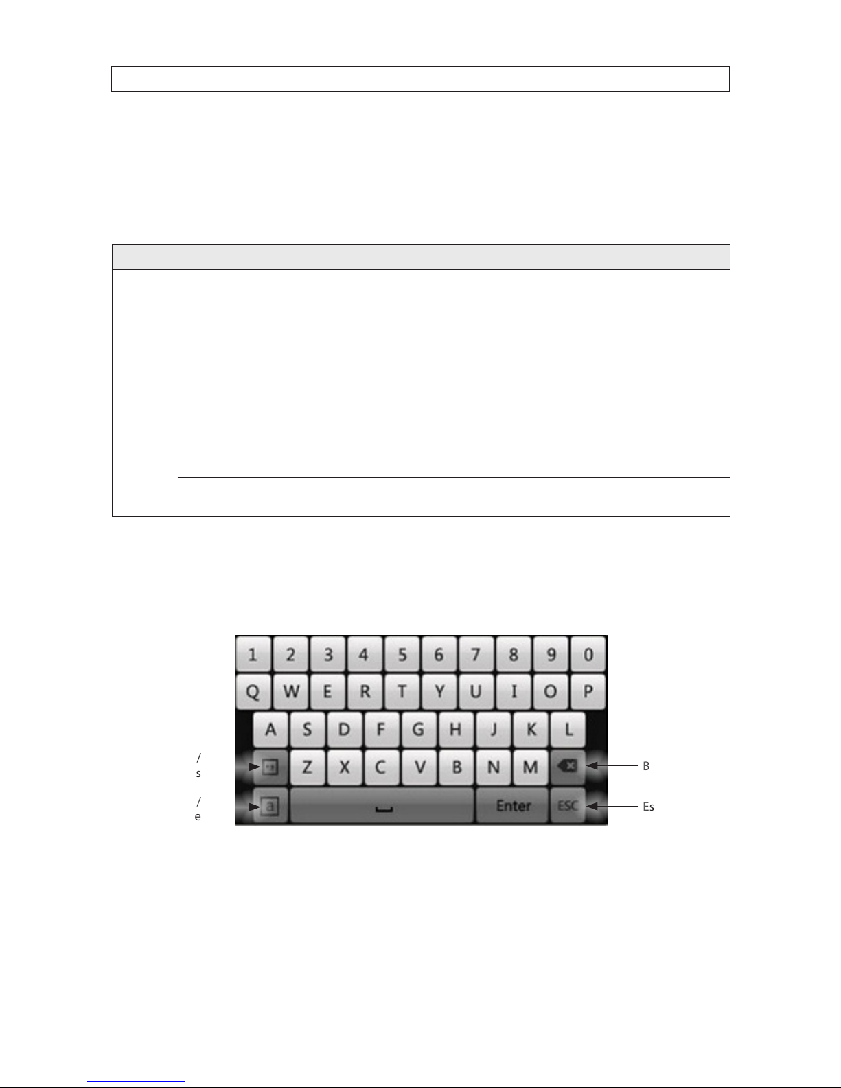
1.1.3 Soft keyboard
An on-screen QUERTY keyboard appears when you click in a eld that accepts a text entry, such as a password or name. The
keyboard is shown in the following picture. Some control keys toggle their function when they are clicked.
Uppercase /
Lowercase
Backspace
Symbols /
Numbers
Escape / Exit
Soft keyboard
SECTION 1: SYSTEM OVERVIEW

7
NVR4020, NVR8040 Embedded NVR User Manual
SECTION 2: INSTALLING THE SYSTEM
SECTION 2
Installing the System
2.1 Getting Started: Unpacking the Equipment
What’s in the box
Your system includes:
• NVR (NVR4020 or NVR8040)
• Remote Control
• USB mouse
• 6 foot Ethernet cable
• 6 foot HDMI cable
• Power cable for NVR
• Interface cables for a 2nd internal hard disk drive
Remove the equipment from its packaging and place it on a at, clean surface. Inspect each item. If any visible damage is present,
contact your supplier for a replacement. Verify that your order is complete.
What you need
Although each security system installation is dierent, most require the following items not included with your system
components:
• VGA or HDMI compatible computer monitor
• IP cameras and cables compatible with the NVR
• Tools to install the cameras and route power and video cables
• Fasteners to attach the cameras to the mounting surfaces
• A display device to connect to the NVR. The NVR will connect directly to a VGA video monitor or an HDMI monitor (HDMI cable
is provided). The display device is usually needed only for system setup. It can be disconnected when the NVR is networked for
access across a LAN or Internet.
• Uninterruptible power supply (UPS). This device is used to ensure system stability during voltage surges, sags, and outages. If a
UPS is not available, a power strip with strong surge protection is highly recommended.
2.2 NVR installation general guidelines
2.2.1 Placement
Your monitoring and recording equipment is the core device for constant surveillance and the reliable capture of video evidence.
Observint Technologies strongly suggest that it be installed in a secure location with access limited to authorized personnel.
8
NVRs and monitors generate heat and should be placed in a clean and well ventilated area. A high temperature environment will
reduce the life span and reliability of the equipment. Additionally, the NVR is not weatherproof, so avoid exposure to liquids and
excessive dust. Do not place objects along the sides or behind the NVR that will block airow through the unit.
Uninterruptible power supplies
It is strongly suggested that power to the system be routed through an uninterruptible power supply (UPS). These devices will keep
your security system running through most power outages, in addition to providing excellent surge and sag protection. The UPS
should support the NVR and all cameras to ensure normal operation during abnormal power conditions.
Proximity to other cameras and the local LAN
Your NVR connect to other devices through Ethernet networks. The NVR4020 and NVR8040 each include two network interfaces:
one to a local area network (LAN) through the LAN connector on the back panel, and the other directly to IP cameras plugged into
the Camera CH1 - CH4 connectors shown on the NVR4020 below, or Camera CH1 - CH8 connectors on an NVR8040.
Camera (CH1 - CH4)
LAN RS-485 Power connector Fan outlet
ON / OFF switchMonitor Out (HDMI, VGA)
Audio IN / OUT
USB
The IP cameras you monitor with your NVR can be connected to either the Ethernet connectors on the back panel or the local LAN.
However, the number of cameras the NVR monitors on the LAN plus the number of those it monitors through the camera channel
connectors on the back panel cannot exceed the channel capacity of your NVR.
If you are using Cat 5e or Cat 6 copper (Ethernet) cable to connect your cameras to the NVR, or other cameras to the LAN, the cable
distance from the NVR (or switch on the LAN) should not exceed 330 feet (100 meters). If a longer cable run is required, the use of
an active hardware device such as a repeater or switch is necessary.
2.3 Install the NVR and monitor
For the following steps, refer to the back panel photo above for the location of connectors.
1. Place the NVR in a location that is secure, well ventilated and clean. The NVR should be positioned such that the back panel
connectors are accessible and the ventilation holes on the sides and top and the fan outlet on the back are not blocked.
2. Install and setup your monitor in accordance with the instructions provided with the monitor. Do not power it on at this time.
3. Cable the HDMI or VGA connector to your monitor’s VGA or HDMI input. The HDMI interface provides the best performance.
4. Plug the mouse into the USB connector on the front or back of the NVR.
SECTION 2: INSTALLING THE SYSTEM

9
NVR4020, NVR8040 Embedded NVR User Manual
SECTION 2: INSTALLING THE SYSTEM
5. If you plan to access your NVR remotely, or congure your NVR to transmit alerts, email, etc. to external servers, plug a drop
cable from your local area network (LAN) into the RJ45 LAN connector on the back of the NVR.
6. Connect the power cord to the power connector on the back panel of the NVR, and then into a UPS (preferred) or surge
protector.
NOTE
Do not power on the NVR at this time.
2.4 Camera installation
Always refer to the documentation provided with the camera for installation instructions. The general guidelines provided below
include information about installing security cameras that is often not found in manufacturer’s documentation. Installing your
cameras with consideration of these guidelines can help improve the performance and reliability of your system.
2.4.1 General Guidelines
Camera placement
Plan your camera installation carefully. Identify the locations where cameras will provide the best coverage, considering:
• Distance from the NVR or LAN switch – if you are using Cat 5e or Cat 6 copper (Ethernet) cable to connect your cameras
to the NVR or LAN switch, the cable distance from the NVR or switch should not exceed 330 feet (100 meters). If a longer cable
run is required, the use of an active hardware device such as a repeater or switch is necessary.
• Field of view – Cameras should be positioned so they can eectively view the entire area that must be monitored, and in a
location where it is dicult to tamper with them.
• Lighting – Light shining directly on the camera lens or bright reections from shiny objects in the eld of view can diminish
video quality and camera performance. Mount the camera in a shaded area, if possible, or where light shining on the lens can
be minimized.
• Ease of installation – It must be possible to install the camera at the location, considering mounting hardware
requirements, mounting surface, contamination, etc.
• Environmental specications – Check the specications to ensure the location where the camera will be installed is
within the environmental constraints of the camera.
About weatherproof cameras
Weatherproof cameras can be mounted in any open area, such as on a telephone pole or on the side of a building. For best results,
we recommend you mount your cameras in a sheltered area, such as under the eave or roof of a building. Point the camera in the
direction you wish to observe.
10
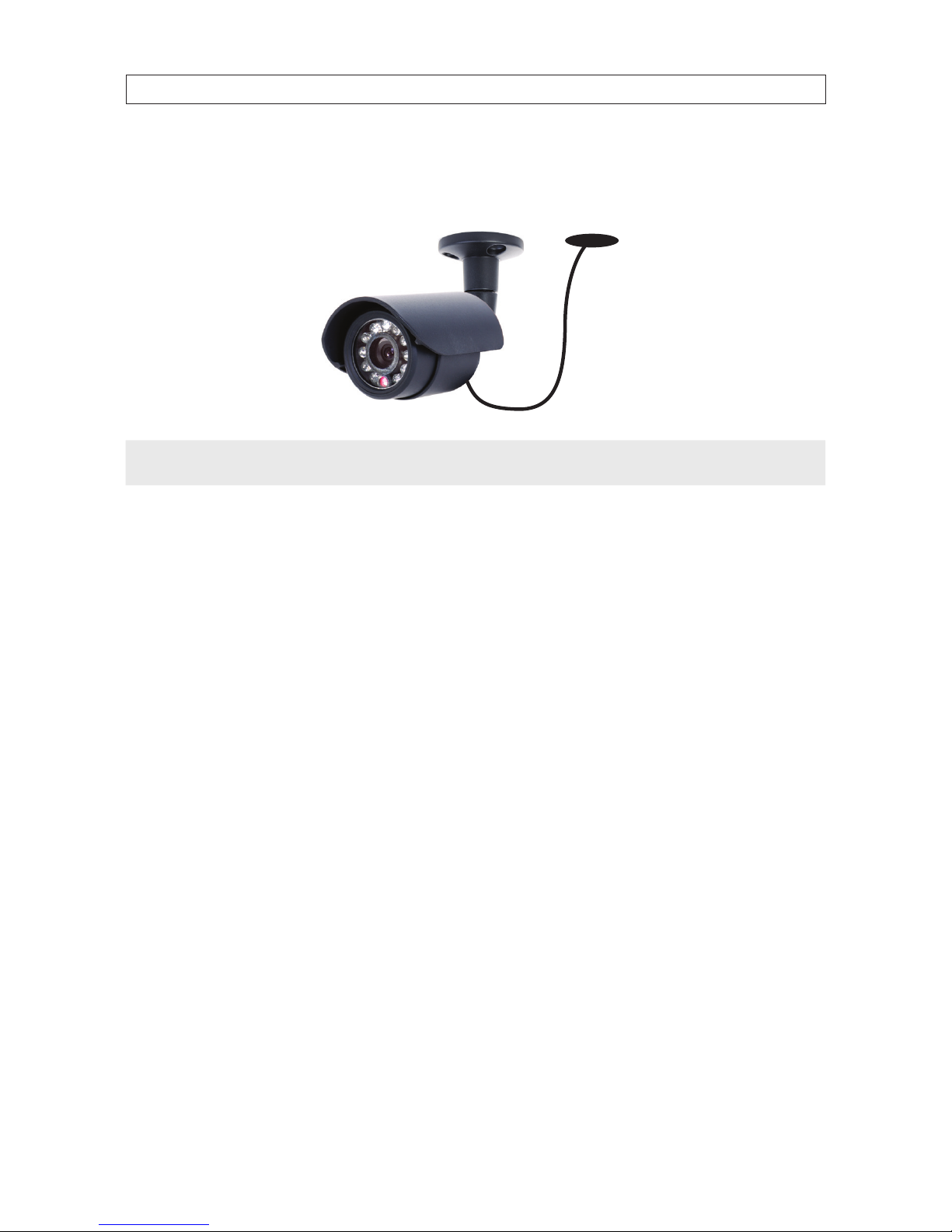
Weatherproof cameras compatible with the NVR8040 and NVR4020 may have cables attached to the camera body and not routed
through the camera base. If these cameras are installed in a moist environment, a drip loop should be constructed in the drop cable
such that moisture will tend to ow away from the camera and drop cable connectors.
Drip Loop
Drop
Cable
NOTE
Cable connectors are not weatherproof.
LAN/power cables can be run almost anywhere, and are frequently routed through attics or above drop/acoustic ceilings because of
the ease of installation. For added security, we recommend you run your cables in areas with limited access to prevent tampering.
Avoid running the cable near high voltage appliances such as uorescent lighting. Electrical noise and magnetic elds produced by
these devices may aect video and communication signal quality.
2.4.2 Install cameras
Install your security cameras as needed to support your security requirements. Always refer to the documentation provided with the
camera for installation instructions.
The RJ45 camera connectors on the back panel of the NVR can connect to only the 3SVision brand IP camera models oered by
Supercircuits. If the cameras you attach to the back panel were used on another system, they should rst be reset to the factory
default conguration before connecting them to the NVR. These cameras can be automatically added to and congured by the NVR
system when the NVR is congured.
IP camera brands other than the 3SVision models can also be monitored by the NVR, but cameras must be connected to the local
LAN the NVR is connected to. These cameras are manually added to the NVR for monitoring using the NVR conguration menus.
See “APPENDIX C Adding Cameras on the LAN to the NVR” on page 112 for procedural guidelines. For a list of compatible camera
models, please contact your support organization.
The NVR4020 will monitor at most four IP cameras, including those connected to the RJ45 camera connectors on the back of the
NVR and those that connect to the NVR through the local LAN interface. Similarly, the NVR8040 will monitor up to eight cameras.
SECTION 2: INSTALLING THE SYSTEM
11
NVR4020, NVR8040 Embedded NVR User Manual
2.5 Connecting it together – initial system setup
1. Plug the LAN cables from the cameras into a connector in the group of RJ45 Ethernet ports on the back of the NVR.
If other cameras to be monitored by the NVR will network to it through the LAN, plug their Ethernet cables into a switch
(router) on the LAN and power on those cameras. (Power to other cameras on the LAN may be provided through a PoE switch
if the camera is PoE capable, or through a separate cable and power adapter).
2. Power on the NVR using the power on / o (I / O) switch on the back panel.
3. Power on the monitor.
NOTE
Some monitors have multiple inputs such including VGA ,HDMI, BNC, etc. If you are using this kind of monitor, congure your
monitor to display the input connected to your NVR (HDMI or VGA).
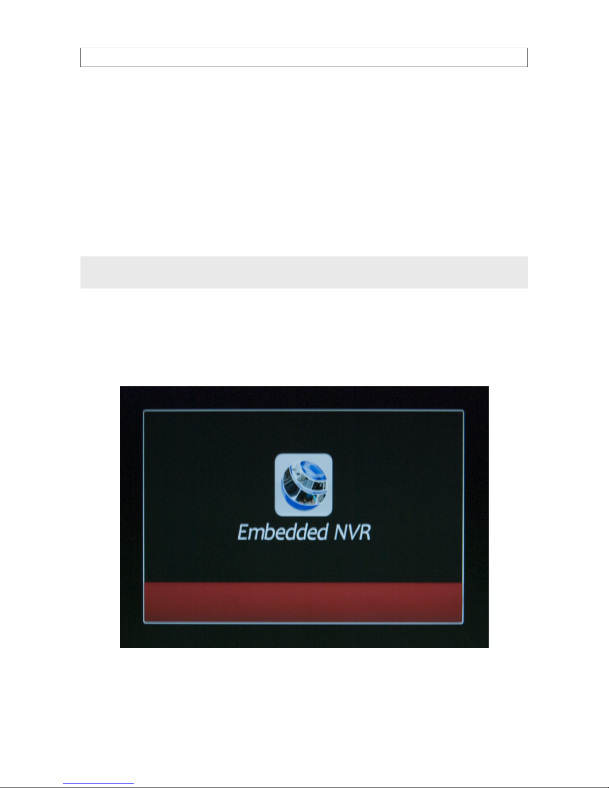
2.5.1 Using the Wizard for basic conguration setup
When the NVR is powered on, an “Embedded NVR” splash screen appears within 2 minutes.
By default, the Setup Wizard opens when the NVR has powered on. The Setup Wizard can assist you in making important
conguration settings in NVR.
SECTION 2: INSTALLING THE SYSTEM
12
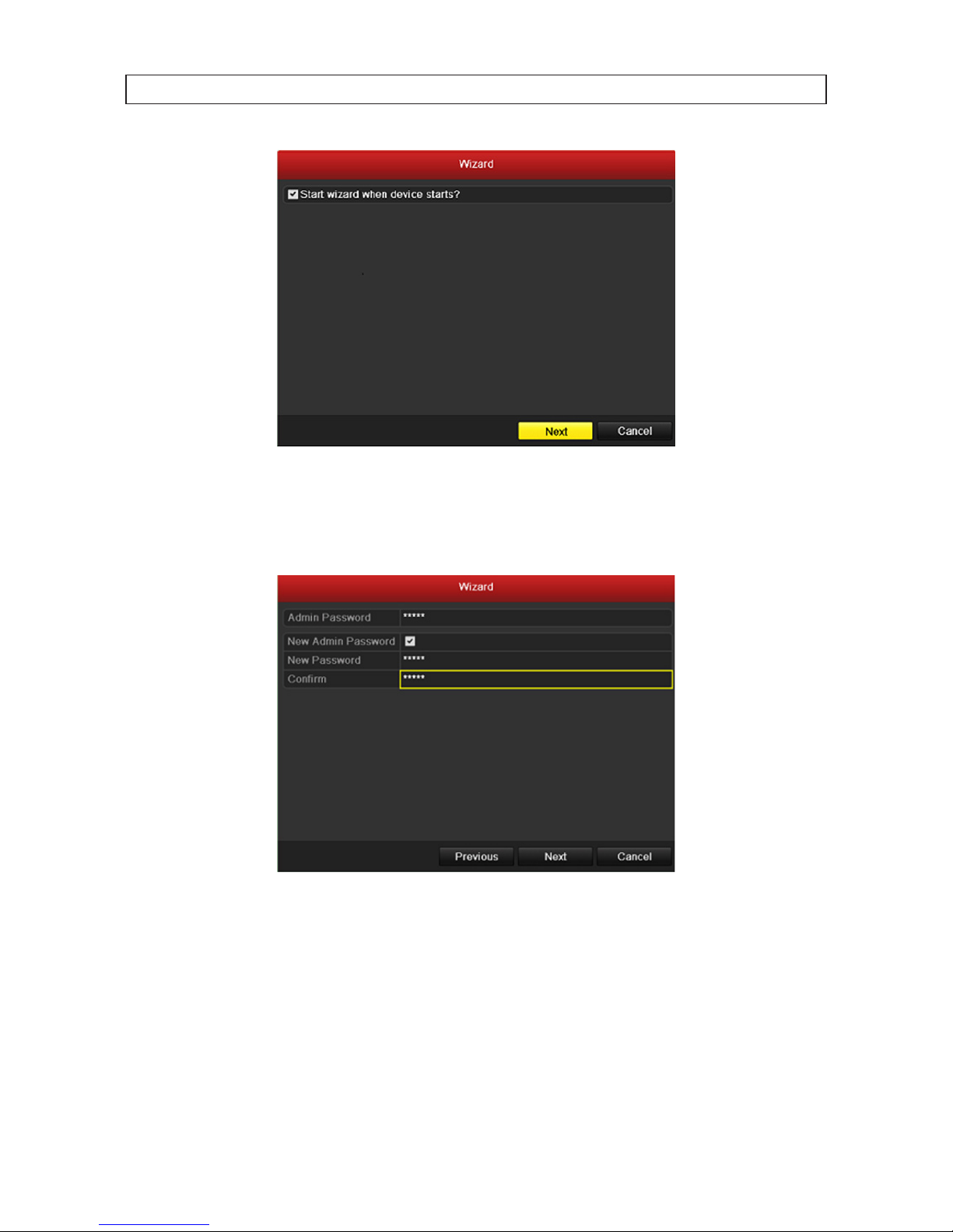
1. Click Next button on the Wizard window to open the Login window.
2. Enter the admin password in the appropriate eld. The default admin password is 12345. To change the admin password,
check the New Admin Password checkbox, then enter the new password in the New Password and Conrm elds.
3. Click the Next button to enter the date and time settings window.
SECTION 2: INSTALLING THE SYSTEM
13
NVR4020, NVR8040 Embedded NVR User Manual
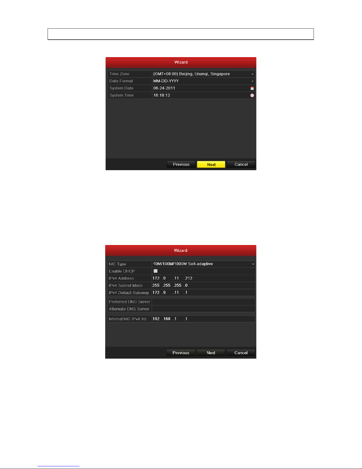
4. In the date and time setup window, click the eld you want to change, then use the drop-down list or setup aid to select
the appropriate values. Click Next to conrm your settings or Cancel to discard them and open the network setup Wizard
window.
5. In the network setup Wizard window, click the eld value you want to change, then use the pop-up aid to enter a new value.
Congure the internal NIC IPv4 Address for the cameras connecting to the Camera channel ports on the back panel of the
NVR.
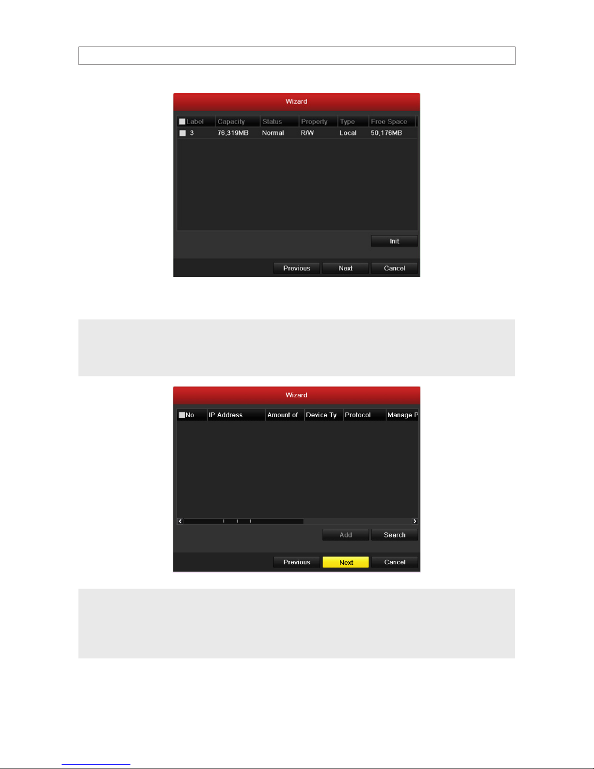
6. Click Next after you congured the network parameters. The HDD management Wizard window will open.
7. To initialize an HDD, click the checkbox for the device you want to initialize, click the Init button, then follow the on-screen
instructions to complete the process. NOTE: Initialization removes all the data saved on the HDD. Click Next to continue.
SECTION 2: INSTALLING THE SYSTEM
14
SECTION 2: INSTALLING THE SYSTEM
8. In the add IP Camera Wizard, click Next.
NOTE
You can add additional IP cameras compatible with the NVR that are active on the local LAN the NVR is networked to. However,
these additional cameras, plus the cameras in use by the NVR that are attached to the RJ45 connectors on the backpanel, cannot
exceed the channel capacity of your system: 4 channels with the NVR4020 or 8 channels with the NVR8040. See “APPENDIX C
Adding Cameras on the LAN to the NVR” on page 112 for procedural guidelines on adding these cameras.
NOTE
The NVR4020 will support, at most, 4 cameras, and the NVR8040 will support, at most, 8 cameras. The number of cameras
attached to the camera channel ports on the back of the NVR, plus the number of cameras on the local LAN congured in the NVR,
cannot exceed the support capacity of the NVR.
If the NVR is congured to camera capacity and you want to add another cameras to the system, it can be done only by replacing a
camera congured in the system with the other one. See “2.7 Adding IP cameras to the NVR” on page 114.
15
NVR4020, NVR8040 Embedded NVR User Manual
SECTION 2: INSTALLING THE SYSTEM
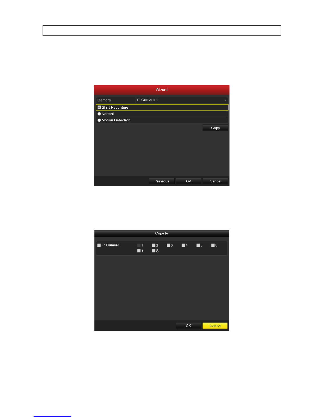
9. Use the camera record mode Wizard as follows:
a. On the Cameras line at the top of the window, open the drop-down list and select the camera you want to congure for
recording.
b. Select one of the recording modes: click Start Recording, then select either Normal or Motion Detection mode.
c. Repeat “a” and “b” above for each camera, and/or click Copy to copy the recording mode of the selected camera to other
cameras in the system.
d. Click OK when the recording mode for each camera is selected. The Wizard will close and the NVR will present the Live
View display. For more information about the Live View display, see “SECTION 4 Live View Interface” on page 29.
16
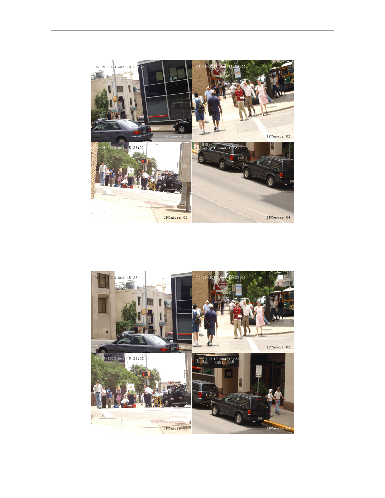
Live View display
10. While viewing video from each cameras in the Live View display, adjust the direction of each camera to aim it at its
surveillance target. Follow the manufacturer’s recommended procedures for aiming the cameras.
Live View display after camera adjustments
SECTION 2: INSTALLING THE SYSTEM

17
NVR4020, NVR8040 Embedded NVR User Manual
2.6 Using the Menu system
After the initial setup of your NVR using the Wizard, the Menus interface enables you to rene your conguration settings and
expand the functionality of the system. To use most menus, the user must log into the NVR system, either locally or remotely, with
administrative privileges.
To open the Menu system from the Live View screen, right click anywhere in the screen, then select Menu
If ID Authentication is not disabled (see the General Settings), a login window will open. In the Login window, select a User Name
with administrative privileges, enter its password, then click OK. A window of Menu icons will open.
2.6.1 Using the Camera menu
The Camera menu lists all cameras congured in the NVR, and shows the channel, IP address, protocol, status, etc. of each. Using
this menu, you can assign names to each camera for easy recognition. For cameras attached to the RJ45 ports on the back of the
NVR, no other conguration changes are required.
SECTION 2: INSTALLING THE SYSTEM

18
To validate the camera information, open the Camera Management menu. Go to Main menu | Camera | IP Camera. This menu
lists the cameras connected to the system.
2.7 Conguring HDD settings
2.7.1 Checking HDD status
Check the status of the HDDs installed in the NVR to assure it is (they are) functioning normally.
1. Open the HDD Information display. Go to Menu | HDD |General
2. Check the status of each HDD. If the status is:
— Normal or Sleeping - The HDD is working normally.
SECTION 2: INSTALLING THE SYSTEM
19
NVR4020, NVR8040 Embedded NVR User Manual
— Uninitialized or Abnormal - Initialize the DDD before use. Check the select box of the HDD to initialize, then click the
Init button at the bottom of the screen.
— Failed - If the HDD failed during or after initialization, replace the HDD.
2.7.2 Managing Network HDD
Additional le storage can be added to your NVR using up to 8 NAS disks, or up to 7 NAS disks with 1 IP SAN disk. To congure this
storage:
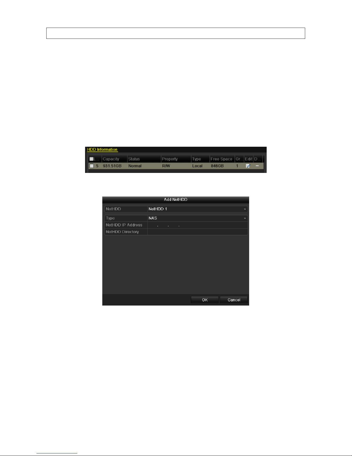
1. Enter the HDD Information interface. Go to Menu | HDD | General
2. Click the Add button to open the Add NetHDD menu.
3. In the NetHDD drop down list, select the NetHDD ID (NetHDD 1 .. NetHDD 8) you want to add.
4. In the Type drop down list select either NAS or IP SAN.
5. Congure the device type you selected.
— For a NAS disk:
i. Enter the NetHDD IP address in the text eld.
ii. Click Search to discover the available NAS disks on the network.
SECTION 2: INSTALLING THE SYSTEM
20
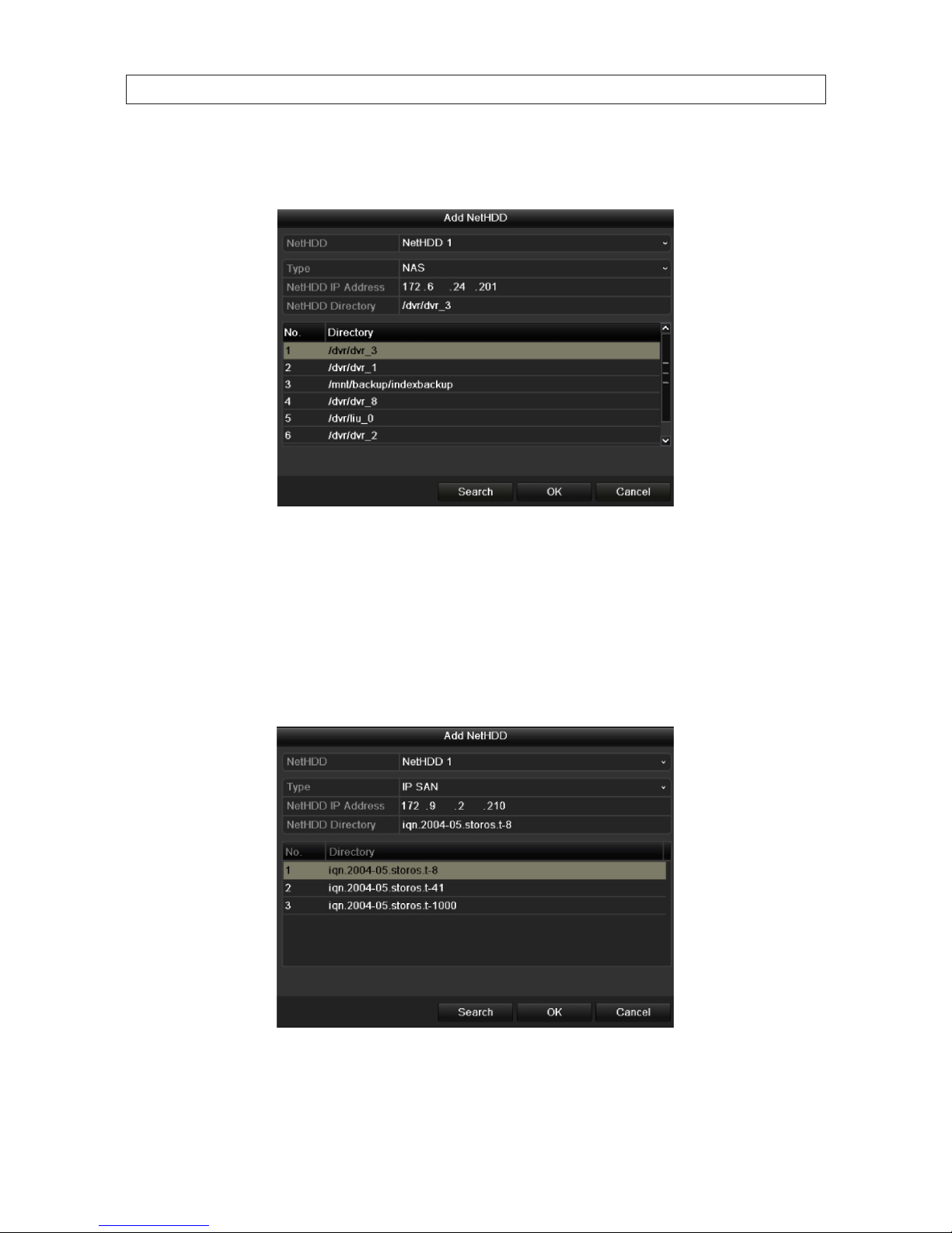
iii. Select the NAS disk from the list shown below, or manually enter the directory in the text eld of NetHDD
Directory.
iv. Click OK to add the NAS disk to your system.
— For an IP SAN disk:
i. Enter the NetHDD IP address in the text eld.
ii. Click Search to discover the available IP SAN disks on the network.
iii. Select the IP SAN disk from the list shown below.
iv. Click OK to add the selected IP SAN disk to your system.
SECTION 2: INSTALLING THE SYSTEM
21
NVR4020, NVR8040 Embedded NVR User Manual
NOTE: If the added NetHDD is uninitialized, select it and click the Init button for initialization. Initializing an HDD erases all
data saved on the disk.
6. Add additional disks as needed up to a maximum of 8 NAS or 7 NAS and 1 IP SAN.
2.7.3 Conguring the HDD
By conguring the encoding parameters you can dene the parameters which aect the image quality, such as the transmission
stream type, resolution, etc.
Before you start:
1. Make sure that an HDD is installed. If not, install a HDD and initialize it. Go to Menu | HDD | General.
2. Click Advanced to check the storage mode of the HDD.
a. If the HDD mode is Quota, set the maximum record capacity. See “2.7.4 Conguring HDD Quota mode” on page 21 for
more information.
b. If the HDD mode is Group, setup the HDD group. F
2.7.4 Conguring HDD Quota mode
Each camera can be congured with an allocated quota for the storage of recorded les. After making conguration changes to the
Storage Mode menu (see below) , the NVR must be restarted for new settings to be applied.
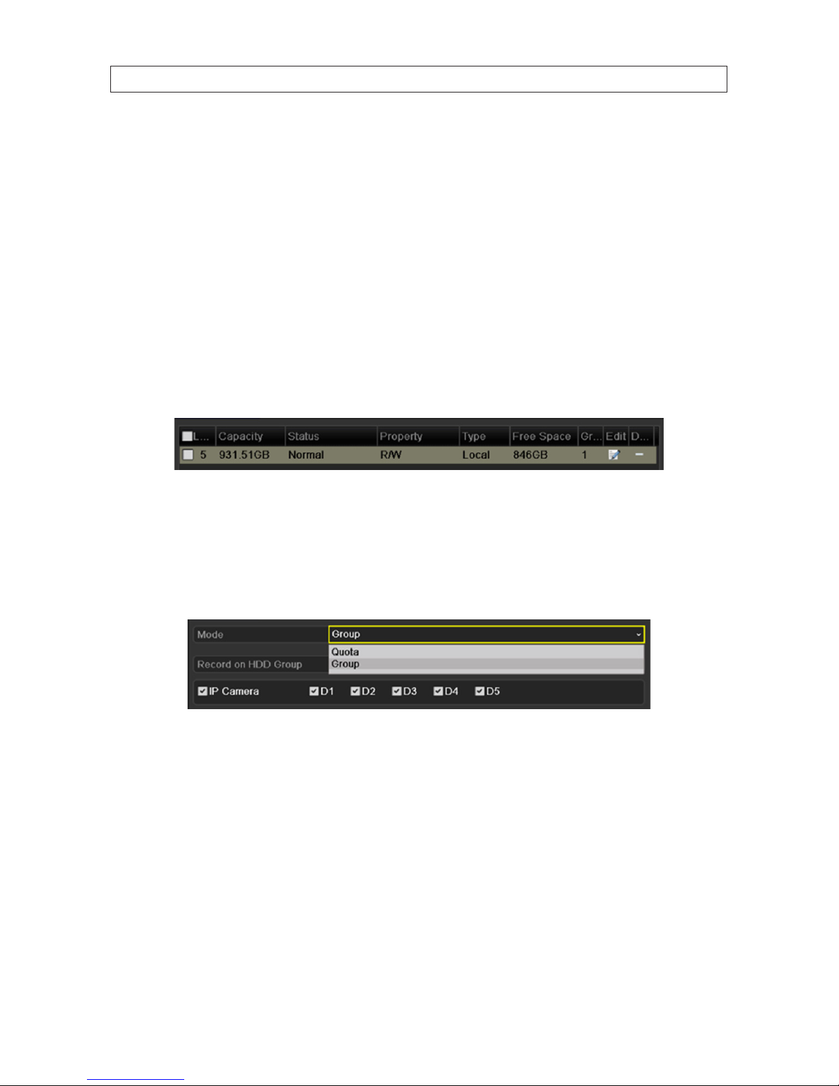
1. Open the Storage Mode menu. Go to Menu | HDD | Advanced
SECTION 2: INSTALLING THE SYSTEM
22
2. On the Mode line, open the drop down list and select Quota.
3. On the Camera line, open the drop down list and select the camera channel you want to congure for Quota mode.
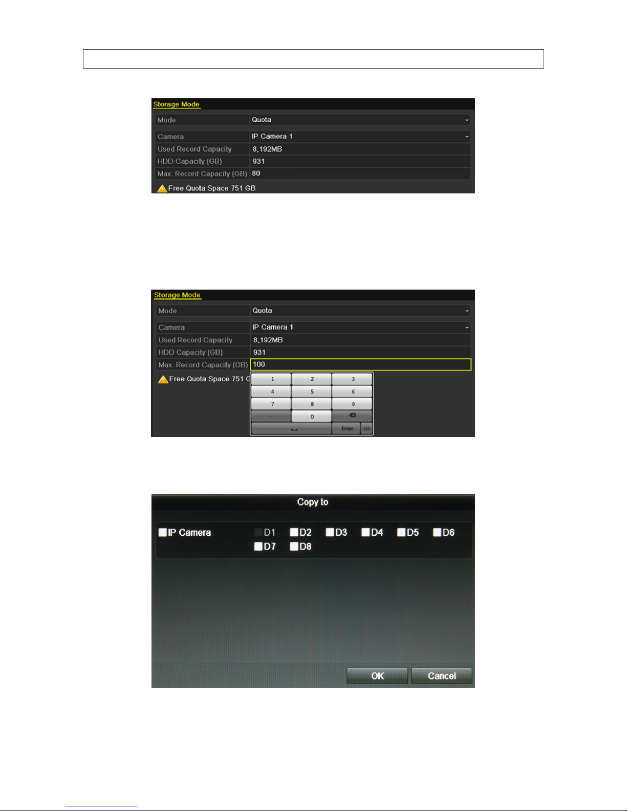
4. Enter the storage capacity in the text eld of Max. Record Capacity (GB)
5. You can copy the quota settings of the current camera to other cameras if required. Click Copy to open the Copy Camera menu.
Note: If the quota capacity is set to 0, then all cameras will use the total capacity of HDD for recordings.
6. In the Copy to menu, check the boxes of the camera channels you want to copy the settings to.
SECTION 2: INSTALLING THE SYSTEM

23
NVR4020, NVR8040 Embedded NVR User Manual
7. Click OK to perform the copy and close the Copy to menu.
8. In the Storage Mode menu, click Apply.
9. Reboot the NVR to activate your quota settings.
2.7.5 HDD Detect
The HDD Detect feature provides two methods of monitoring the HDD: display of S.M.A.R.T. (Self-Monitoring, Analysis and
Reporting Technology) data, and Bad Sector Detection. These methods can be used to assure the normal functioning of the disk,
and anticipate failures.
S.M.A.R.T. Display
1. Open the S.M.A.R.T. display menu. Go to Menu | HDD | HDD Detect
2. To execute a self-evaluation test on an HDD:
a. On the HDD line, open the drop down list to select the HDD of interest.
b. On the Self-test Type line, open the drop down list to select the type of test to execute. You can choose either Short
Test, Expanded Test or Conveyance Test.
c. Click the icon on the S.M.A.R.T. line to execute the test. Allow the test to complete before continuing. The result of the test
is shown on the Self-evaluation line.
SECTION 2: INSTALLING THE SYSTEM

24
3. Examine the S.M.A.R.T. data provided for the HDD. Check to ensure that the data in the value and Worst column does not
exceed the data in the Threshold column.
NOTE: S.M.A.R.T. data provided by each HDD manufacturer is usually dierent. Refer to the manufacturer’s website for
S.M.A.R.T. data denitions.
Bad Sector Detection
1. Open the Bad Sector Detection menu. Go to Menu | HDD | HDD Detect | Bad Sector Detection
2. On the HDD No. line, open the drop down list and select the number of the HDD you want to test.
3. Click the Detect button to start the detection. Bad sectors are identied in the array as red colored cells.
SECTION 2: INSTALLING THE SYSTEM

25
NVR4020, NVR8040 Embedded NVR User Manual
Click Pause to temporarily stop the scan, and click Cancel to end the scan.
Click Error info to see the detailed damage information.
2.8 Conguring Exception Alarms
The NVR8040 and NVR4020 monitor for and respond to certain system-related alarm conditions (exception alarms). Monitoring for
and response to these exceptions are congurable.
Exception alarm conditions include:
• HDD Full: The HDD is full.
• HDD Error: Writing HDD error or unformatted HDD.
• Network Disconnected: Disconnected network cable.
• IP Conicted: Duplicated IP address.
• Illegal Login: Incorrect user ID or password.
• Record Exception: No space exists for saving recorded les.
Responses to exception alarms include:
• Audible Warning: Trigger an audible beep when an alarm is detected.
• Notify Surveillance Center: Sends an exception or alarm signal to remote alarm host when an event occurs. The alarm host
refers to the PC installed with Remote Client. Note: The alarm signal will be transmitted automatically at detection mode to
the Alarm Host IP and Port congured in the Conguration | Network | More Settings menu.
• Send Email: Send an email with alarm information to a user or users when an alarm is detected.
To congure exception alarms:
1. Open the Exception menu. Go to Menu | Conguration | Exceptions
2. On the Exception Type line, open the drop down list and select the exception condition you want to congure. If you select
All, all exception conditions will be treated the way you congure the response.
3. Select any of the following response options: Audible Warning, Notify Surveillance Center, Send Email. NOTE: At this time, the
NVR does not support the Trigger Alarm Output option.
SECTION 2: INSTALLING THE SYSTEM

26
4. Click Apply to save your settings.
5. Repeat these steps for other Exception Types you want to congure.
SECTION 2: INSTALLING THE SYSTEM

27
NVR4020, NVR8040 Embedded NVR User Manual
SECTION 3
Startup, Shutdown, Reboot
After the NVR and cameras are installed, the NVR system must be congured to function in the surveillance mode(s) that best serve
your needs. This chapter includes the essential steps to get your system running, including conguring the NVR date and time, and
setting up the LAN interface, cameras and recording modes. Advanced features, including remote access, video export, adding user
names and setting user permissions, etc. are described in later sections of this manual.
3.1 Starting Up, Shutting Down and Rebooting the NVR
3.1.1 Startup
Proper startup and shutdown procedures are essential for getting the most out of your NVR. To startup:
1. Check the power cable is plugged into a standard electrical outlet. It is HIGHLY recommended that an Uninterruptible Power
supply (UPS) be used in conjunction with the device.
2. Rock the POWER switch on the back panel to the on (“I”) position. The Power indicator LED on the front panel should turn
green indicating that the unit is powered on.
3. After startup, the Power indicator LED remains green. A splash screen will appear on the monitor.
3.1.2 Shutdown
To shut down the NVR:
1. Right click anywhere on the desktop to open the pop-up window, then select Menu.
2. If a Login window opens, select a User Name with administrative privileges, enter the appropriate Password, then click OK.
SECTION 3: STARTUP, SHUTDOWN, REBOOTEM

28
NOTE
The default User Name with administrative privileges and its associated Password are admin and 12345.
3. In the Menu window, click the Shutdown icon, then click Shutdown in the pop-up window.
4. Click Yes in the Attention window.
5. When the message Please power o! appears, rock the power switch on the back panel to the o (“O”) position.
3.1.3 Rebooting the NVR
In the Shutdown menu, you can also reboot the NVR.
1. Enter the Shutdown menu by clicking Menu | Shutdown.
2. Click the Reboot button to reboot the NVR.
SECTION 3: STARTUP, SHUTDOWN, REBOOT

29
NVR4020, NVR8040 Embedded NVR User Manual
SECTION 4
Live View Interface
The Live View interface is the primary camera viewing and monitoring mode. It can be congured to present video from the
cameras congured in the system singularly or in multi mode, or using a “patrol” feature wherein video from each of a select group
of cameras is displayed singularly and sequentially, with each camera view shown for a preset duration (dwell). The Live View
screen can be congured to display 1, 6 or 8 camera channels concurrently, or playback recorded video.
Live View 2 * 2 multi-screen display
Each camera channel displayed on the Live View screen may contain one or both status icons in the upper-right corner of the
viewing frame.
Live View Status icons
Icon Type Reason
Alarm Video loss, tampering, motion dete ction or sensor alar m
Record Manual record, schedule record, motion detection or alarm triggered record
SECTION 4: LIVE VIEW INTERFACE

30
Icon Type Reason
Recor d and Alarm Both alarm and record s tatus
4.1 Quick Setting Toolbar
Left-clicking the mouse on a viewing frame opens a Quick Setting Toolbar at the top or bottom of the frame.
Instant playback
Live view strategy
Digital
zoom
PTZ control
Enable/disable
manual record
CloseImage setting
Mute/audio on
Instant Playback: Plays what was recorded in the previous ve minutes. Nothing is played if a recording was not made at that
time.
PTZ Control: PTZ control is not supported.
Digital Zoom: Shows the selected portion of the camera image in full-screen mode. To select an area, left-click and drag to form a
rectangle across the area to expand. See the gure below.
Zoom selection area
Image Settings: Click this icon to open menus for creating customized setting for the brightness, contrast, saturation and hue of
the camera image. After making an adjustment on in this menu, the NVR will respond within a few seconds. Click OK when your
adjustments are complete.
SECTION 4: LIVE VIEW INTERFACE

31
NVR4020, NVR8040 Embedded NVR User Manual
Live View Strategy: Use this feature to select Real-time, Balanced, Fluency. These features can improve the display of the camera
channels.
4.2 Live View pop-up menu
Right-clicking the mouse on the desktop opens the pop-up window shown below.
Clicking one of the items listed produces the result described below.
— Menu: Opens the conguration menu window. See “SECTION 5
Record, Playback and Video Backup” on page 34.
— Single Screen: showing only one camera channel on the monitor. Open the drop-down list to select the camera
channel you want to view.
SECTION 4: LIVE VIEW INTERFACE

32
— Multi-screen: opens a submenu where you can choose from several multi-channel screen congurations, including
2 *2, 1+5, 1+7, 3*3, in multi-screen mode, you can view video from multiple camera channels simultaneously.
— Previous screen: Move to the screen displayed previously.
— Next screen: Move to the screen displayed after the current one.
— Start Auto-switch: the screen is automatically switched from one camera channel to the next. You must set the dwell
time before enabling auto-switch. Go to Menu | Conguration | Live View | Dwell Time.
— Start Recording: Select Normal Record and Motion Detection record from the drop-down list.
— Output Mode: opens a menu where you can select the output mode to Standard, Bright, Gentle or Vivid.
— All-day Playback: Opens a playback menu where you can playback video recorded at a specic time of the day. In If
in Multi-screen mode, double-click on the viewing frame of the camera recording video you want to replay, then select
All-day Playback. A marker on the timeline shows the time recording being played back was made.
4.2.1 Live View settings
Live View settings can be customized according to diering needs. You can congure the screen frame split, placement of camera
channels on the screen, dwell time for screen to be shown, mute or turning on the audio, the screen number for each channel, etc.
1. Open the Live View Settings menu. Go to Menu | Conguration | Live View
Adjust the settings in the screen as needed:
— Video Output Interface: Designates the output to congure the settings for. Option includes only VGA/HDMI.
— Live View Mode: Designates the display mode (screen split) to be used for Live View.
— Dwell Time: The time in seconds to dwell between switching channels when auto-switch is enabled in Live View.
— Enable Audio Output: Enables/disables audio output for the selected video output.
— Event Output: Designates the output to show event video. Option includes only VGA/HDMI.
— Full Screen Monitoring Dwell Time: The time in seconds to show alarm event screen.
2. After changing settings in the screen shown above, click Apply, and then click Back.
3. Click the View tab at the top of the screen.
SECTION 4: LIVE VIEW INTERFACE

33
NVR4020, NVR8040 Embedded NVR User Manual
Single-, multi-screen select icons Viewing screens
4. Click the single- or multi-screen select icon for the screen split you prefer. In the example shown above, a 2*2 screen is
selected.
5. Click a viewing screens, then double-click the camera in the list on the right that you what to show there. When the selection
is made, label in the viewing screen changes to the camera channel number. In the example above, only the top two screens
are assigned.
6. Click the Apply button to save your setting.
SECTION 4: LIVE VIEW INTERFACE

34
SECTION 5
Record, Playback and Video Backup
After the initial setup of your NVR using the Wizard, the Menus interface enables you to rene your conguration settings and
expand the functionality of the system. To use most menus, the user must log into the NVR system, either locally or remotely, with
administrative privileges.
To open the Menu system from the Live View screen, right click anywhere in the screen, then select Menu.
After selecting Menu, a login window will open. In the Login window, select a User Name with administrative privileges, enter
its password, then click OK. A window of Menu icons will open. NOTE: When the system option Enable ID Authentication is
disabled (see the Conguration - General settings submenu), the Login window to open the Menu does not appear.
SECTION 5: RECORD, PLAYBACK AND VIDEO BACKUP

35
NVR4020, NVR8040 Embedded NVR User Manual
5.1 Conguring record settings
5.1.1 Setting camera encoding parameters
1. Enter the Record settings interface to congure the encoding parameters. Go to Menu | Record | Encoding.
2. Select the Record tab page you want to congure. You can congure the stream type, the resolution, and other parameters.
— Pre-record: The length of time you set to record before the scheduled time or event. For example, when an alarm
triggered the recording at 10:00, if you set the pre-record time as 5 seconds, the camera records it at 9:59:55.
— Post-record: The length of time you set to record after the event or the scheduled time. For example, when an alarm
triggered the recording ends at 11:00, if you set the post-record time as 5 seconds, it records till 11:00:05.
— Expired Time: The expired time is the longest time a recording is kept on the HDD. If the deadline is reached, the le
will be deleted. If you set the expired time to 0, the le will not be deleted. This parameter is usually determined in
consideration of the capacity of the HDD.
— Record Audio: Check the checkbox to enable audio recording.
3. Click Apply to save your new conguration settings.
4. Open the Sub-stream tab page.
a. Congure the parameters of the camera.
b. Click Apply to save the settings.
SECTION 5: RECORD, PLAYBACK AND VIDEO BACKUP

36
5.1.2 Conguring Record schedule
The record schedule can be used to automatically start and stops recording at preset times. NOTE: Alarm triggered recording is not
enabled in the NVR8040 or NVR4020.
1. Open the Record Schedule menu. Go to Menu | Record | Schedule
2. To congure the Record schedule:
a. Open the Camera drop-down list to select the camera you want to congure.
b. Check the Enable Schedule box.
c. Click Edit, or use the graphical method to apply recording modes to hours of the day.
i. If you clicked the Edit button, a record schedule list opens.
— Open the Schedule line drop down list and select the day you want to create a record schedule for.
SECTION 5: RECORD, PLAYBACK AND VIDEO BACKUP

37
NVR4020, NVR8040 Embedded NVR User Manual
— To schedule all-day recording, check the checkbox after the All Day item. To setup specic start and end times,
click the clock icon to open a time setting popup window.
— In the Type column, select the type of recording trigger you want to use. “Normal” recording is continuous
recording. “Motion” recording is recording triggered by some kind of motion detected in the video image.
Alarm recording is not supported.
— Click Apply to save your settings.
NOTE
You can dene up to eight recording time periods for each day, each with a specied recording type. Recording
time periods cannot overlap with each other. Each recording period can use either Normal or Motion triggered
recording.
— Repeat the steps above to schedule recording for other days of the week. If the same schedule can also be
applied to other days, click Copy (see the window below), select the days you want to copy the schedule to,
then click OK.
ii. To use the graphical method to draw the schedule:
— Click the color icons for either Normal or Motion in the right panel.
SECTION 5: RECORD, PLAYBACK AND VIDEO BACKUP

38
— Drag the mouse pointer across the area of the chart (day of the week, hours of the day) where you want to
use that type of recording. Blocks on the chart, each representing 1 hour of one day, will be colored for the
recording mode you selected. A descriptions of the color icons are shown in the gure below.
Normal recording
Not used
Not used
Recording triggered by motion
Not used
Clear recording mode
— Click Apply to validate the settings.
SECTION 5: RECORD, PLAYBACK AND VIDEO BACKUP

39
NVR4020, NVR8040 Embedded NVR User Manual
3. If the settings can be applied to other camera channels, click Copy.
4. In the Copy menu, click the channels you to which you want to copy the schedule to, then click OK.
5.1.3 Conguring Motion Detection Recording
Follow the steps to set the motion detection parameters. A motion detection events can trigger several kind of actions by the NVR,
including channels to start recording, full screen monitoring, an audio warning, notication sent to the surveillance center, etc.
Follow the steps below to schedule a recording triggered by a motion detection.
1. Open the Motion Detection menu. Go to Menu | Camera | Motion
SECTION 5: RECORD, PLAYBACK AND VIDEO BACKUP

40
2. To congure Motion Detection:
a. Choose camera you want to congure.
b. Check the Enable Motion Detection box.
c. Use the mouse to drag a rectangle across the area where you want to detect motion. If you want to sense for motion
detection in all areas of the video, drag a rectangle across the entire video screen. You can select up to three areas
(rectangles on the screen) where motion will be detected.
NOTE: The example shown here is for a 3SVision camera. Other camera brands and models have dierent methods for
designating the motion detection areas.
SECTION 5: RECORD, PLAYBACK AND VIDEO BACKUP

41
NVR4020, NVR8040 Embedded NVR User Manual
To clear one of the areas, click the Clear Zone button associated with the color of the rectangle. To clear all zones you
dened, click Clear All.
d. Click Handling, to open the Handling Trigger Channel tab window.
e. In the Handling Trigger Channel window, select the channels you want the record when the motion detection event
occurs, then click Apply to save your settings.
f. Click the Arming Schedule tab. With the Arming Schedule, you can dene up to eight time periods during each day of
the week when motion detection is monitored. Time periods cannot overlap.
SECTION 5: RECORD, PLAYBACK AND VIDEO BACKUP

42
g. Click Apply to save the settings. You can also click Copy to copy the Arming Schedule setup in the window to other days
of the week.
h. Click the Handling tab. In the Handling tab, you can cause certain actions to occur when motion triggered recording
occurs.
-
i. Select the actions you want to occur, then click Apply to save your settings, and OK to return to the Motion Detection
menu.
NOTES: The Trigger Alarm Output option is not functional in the NVR8040 and NVR4020.
The Notify Surveillance Center and Send Email options require additional network settings. See
“SECTION 7 Network Settings” on page 80 for more information.
SECTION 5: RECORD, PLAYBACK AND VIDEO BACKUP

43
NVR4020, NVR8040 Embedded NVR User Manual
SECTION 5: RECORD, PLAYBACK AND VIDEO BACKUP
5.1.4 Manual record
Follow the steps below to begin manual recording. Manual recording, once initiated, requires a manual cancel of the record. The
manual recording can occur prior to the scheduled recording.
1. Open the Manual settings menu. Go to Menu | Manual.
2. To enable Manual Record:
a. Select Record on the left menu frame.
b. Click the status button before camera number to change the label from OFF to ON, if necessary.
c. Click the icon after Norman or Motion Detection.
d. When the Attention window opens, click Yes.
3. To disable Manual Record:
a. Select Record on the left menu frame.
b. Click the status button before camera number to change the label from ON to OFF.
c. Click the icon after Norman or Motion Detection.
d. When the Attention window opens, click No.

44
NOTE
Green “ON” icon means that the channel is congured with a record schedule.
If the NVR is rebooted, manual record operations are canceled.
5.1.5 Conguring Holiday recording
Follow the steps below to congure the record schedule on holiday for that year. You may want to have dierent plan for recording
on holidays.
1. Enter the Record setting interface. Go to Menu | Record | Holiday
2. To Edit Holiday schedule.
a. Click the icon in the Edit (right) column of the line you want to edit. The Edit window will open.
SECTION 5: RECORD, PLAYBACK AND VIDEO BACKUP

45
NVR4020, NVR8040 Embedded NVR User Manual
b. In the Edit menu, check the Enable box.
c. Select Mode from the drop-down list to select the duration. There are three dierent modes for the date format to
congure holiday schedule: Date, Week, and Month.
d. Set the start and end dates.
e. Click Apply to save settings.
f. Click OK to exit the Edit menu.
3. Open the Record Schedule settings menu to edit the holiday recording schedule. See “5.1.2 Conguring Record schedule” on
page 36.
5.1.6 Conguring HDD Group for Recording
You can group the HDDs and save the record les in a specic HDD group. You must have multiple HDDs installed in the system to
perform this conguration.
1. Open the HDD menu. Go to Menu | HDD
2. Click Advanced in the left frame to open the Storage Mode menu.
SECTION 5: RECORD, PLAYBACK AND VIDEO BACKUP

46
3. Verify that the HDD mode is Group. If not, set it to Group, then click Apply and follow the on-screen instructions to reboot the
NVR. See Return to the HDD menu.
4. Click General in the left frame.
5. Click the icon in the Edit column for the HDD to open the editing menu. To select the HDD group:
a. Choose a group number for the HDD group.
b. Select the channels you want to save in this group.
c. Click Apply and then in the pop-up message box, click Yes to save your settings.
d. Click OK to go to the menu window.
6. Repeat the steps above to congure more HDD groups.
5.1.7 Files Protection
You can lock the recorded les or set the HDD property to Read-only to protect the record les from being overwritten.
1. Open the Export menu. Go to Menu | Export
2. Check the box(es) for the channel(s) you want to investigate.
3. Congure the record type, File Type (locked or unlocked), and Start Time and End Time.
SECTION 5: RECORD, PLAYBACK AND VIDEO BACKUP

47
NVR4020, NVR8040 Embedded NVR User Manual
4. Click Search to show the results.
5. To protect the record les:
a. Determine which les you want to protect, and then click the icon in the Lock column to show a “locked” padlock
(indicating that the le is locked). Similarly, unlock les by clicking on the “locked” icon to show an “unlocked” padlock.
b. Respond appropriately to the Attention pop-up window.
NOTE
File of recording in progress cannot be locked.
5.2 Playback
5.2.1 Playing back video by channel
Playback the recorded video les of a specic channel in the live view mode. Channel switch is supported.
SECTION 5: RECORD, PLAYBACK AND VIDEO BACKUP

48
Instant playback by channel
In Live View mode, click the channel you want to playback, then click the playback icon on the quick setting toolbar. In the instant
playback mode, only recordings made during the previous ve minutes on the channel are played.
Playback by channel
1. Open the Playback menu. Go to Menu | Playback.
2. In the Playback screen, select the camera channel you want to playback. De-select the other channels.
3. Select the start and end times of the video segment you want to play.
SECTION 5: RECORD, PLAYBACK AND VIDEO BACKUP

49
NVR4020, NVR8040 Embedded NVR User Manual
4. Click the Search button.
5. In the window that opens, click the entry of the video segment you want to play, then click the icon in the Play column.
6. In the screen that opens, select the camera or cameras you want playback, then click OK to continue. By default, only the
camera of the video you selected will play.
SECTION 5: RECORD, PLAYBACK AND VIDEO BACKUP

50
To open the Results list ( the right frame - see above), move the mouse pointer to the right edge of the screen. You can play
a dierent video segments by clicking the segment to highlight it, then clicking the Play icon associated with it. Move the
mouse pointer away from the right side to close the frame.
The Playback control panel is shown below. The line across the top of the control panel shows the mode that initiated the
recording. In the example above, the entire recording resulted from a normal, continuous recording conguration option.
Video Search Hide Exit
Record mode
color key
Video playback controls
File position, playback time of dayPosition marker Record mode indicator bar
Mute Add
default
tag
Add
custom
tag
Tag
management
Start/stop
clip
SECTION 5: RECORD, PLAYBACK AND VIDEO BACKUP

51
NVR4020, NVR8040 Embedded NVR User Manual
Video playback controls allow you to control the speed and direction of the playback. You can also drag the le position marker
to another position in the le.
You can hide the control panel during playback by clicking the Hide icon in the lower right corner. To exit playback, right click in
the video frame, then select Exit, or click the Exit icon in the lower right corner.
The tag management icons in the lower left corner allow you to “tag” the video segment with a unique name. Click the Add
Tag icon to open the Add Tag pop-up menu, then enter a Tag name. Tagged videos can easily searched for and retrieved later.
Right click anywhere on the video frame to open a pop-up menu. With this menu, you can return to Video Search, zoom in on
the video, open and close the control panel at the bottom of the screen, and Exit.
5.2.2 Playing back a motion event
The NVR4020 and NVR8040 can search for and playback recordings triggered by motion events.
1. Open the Playback menu. Go to Menu | Playback
2. In the left frame, click Event.
SECTION 5: RECORD, PLAYBACK AND VIDEO BACKUP

52
3. In the drop Event Type down-down list, select, for example, Motion.
4. Open the calendar and time pop-up windows to select the Start Time and End Time of the timespan you want to search.
5. Check the boxes of the cameras associated with the motion search.
SECTION 5: RECORD, PLAYBACK AND VIDEO BACKUP

53
NVR4020, NVR8040 Embedded NVR User Manual
6. Click Search to generate a list of motion detected events.
7. Select the video clip from the list, then click the Play icon associated with it.
SECTION 5: RECORD, PLAYBACK AND VIDEO BACKUP

54
The control panel at the bottom of the screen is described earlier in this section. See “5.2.1 Playing back video by channel” on
page 47.
8. To open the search result list during video playback, move the mouse cursor to the right edge of the screen.
9. To playback a dierent motion event video clip, click the segment to highlight it, then click the associated Play icon.
5.2.3 Playback by Tag
You can easily search for and play back video les that were tagged.
1. Open the Playback menu. Go to Menu | Playback
2. In the left frame, click Tag.
3. Check the boxes of the cameras associated with the tagged video les.
4. Open the calendar and time pop-up windows to select the Start Time and End Time of the timespan you want to search.
SECTION 5: RECORD, PLAYBACK AND VIDEO BACKUP

55
NVR4020, NVR8040 Embedded NVR User Manual
5. Click Search to generate a list of tagged video les.
SECTION 5: RECORD, PLAYBACK AND VIDEO BACKUP

56
6. Select the video clip from the list, then click the Play icon associated with it.
The control panel at the bottom of the screen is described earlier in this section. See “5.2.1 Playing back video by channel” on
page 47.
7. To open the search result list during video playback, move the mouse cursor to the right edge of the screen.
8. To playback a dierent motion event video clip, click the segment to highlight it, then click the associated Play icon.
SECTION 5: RECORD, PLAYBACK AND VIDEO BACKUP

57
NVR4020, NVR8040 Embedded NVR User Manual
In the screen above:
— Click the Add default tag icon in the lower left corner of the screen during video playback to add a default tag.
— Click the Add customized tag icon in the lower left corner of the screen during video playback to add a customized tag.
NOTE: You can add up to 64 tags to a single video le.
Tag management.
The tag management feature allows you to check, edit, and delete tags.
1. Click the Tag management icon in the lower left corner of the screen to open the Tag management window.
SECTION 5: RECORD, PLAYBACK AND VIDEO BACKUP

58
— To change the name of a tag, select (highlight) a tag in the list, then click the icon in the Edit column.
* Click the tag name, use the pop-up keyboard to change the name, click Enter, then click OK.
— To delete a tag, select (highlight) a tag in the list, then click the icon in the Delete column.
5.2.4 Playback from System Logs
You can search for video clips through system logs. System logs include the following types of entries:
• Alarms events - Start/stop motion detection, start/stop tamper detection etc.
• Exception conditions - Video loss, illegal login, HDD full/error, IP camera disconnected, network disconnected, etc.
• Information events - Start/stop recording, local/network HDD information, HDD S.M.A.R.T., etc.
• Operation events - power on, login, local operation logout, etc.
1. Open the Log Information screen. Go to Menu | Maintenance | Log Information
2. Click Log Search tab to enter Playback by System Logs.
SECTION 5: RECORD, PLAYBACK AND VIDEO BACKUP

59
NVR4020, NVR8040 Embedded NVR User Manual
3. Select a Start Time, End Time, Major Type and Minor Type.
SECTION 5: RECORD, PLAYBACK AND VIDEO BACKUP

60
4. Click Search. If the search didn’t nd a le matching your search criteria, the message No matched log le. will appear.
5. Choose a log with record le and click the playback button to play the le, or click the icon in the Details column to see more
information about the entry. If there is no playback le associated with the log entry, the message box No result found. will
appear. The Log Information Details screen is shown below.
SECTION 5: RECORD, PLAYBACK AND VIDEO BACKUP

61
NVR4020, NVR8040 Embedded NVR User Manual
5.2.5 Auxiliary Functions - Playback frame by frame
Play video les frame by frame, in case of checking image details of the video when abnormal events happen.
Using a Mouse:
Go to Menu | Playback
Playback a le. During playback, click the button tt until the speed changes to Single. One click on the playback screen
advances playback to the next frame forward. Click uu to increase the playback speed in forward.
IDuring reverse playback click the button tt until the speed changes to Single. One click on the playback screen advances
playback to the next frame in reverse. Click uu to increase the playback speed in reverse.
5.2.6 Auxiliary Functions - Reverse Playback of Multi-channel
You can play back record les of multi-channel reversely. Up to 8-ch (with 1280*720 resolution) simultaneous reverse playback is
supported; up to 4-ch (with 1920*1080p resolution) simultaneous reverse playback is supported and up to 1-ch (with 2560*1920
resolution) reverse playback is supported.
1. Open the Playback menu. Go to Menu | Playback
2. On the IP Camera line, select multiple IP cameras by checking the boxes associated with them.
SECTION 5: RECORD, PLAYBACK AND VIDEO BACKUP

62
3. Click Playback to play back the record les reversely.
5.2.7 Digital Zoom
1. Click the magnier button on the playback control bar to enter Digital Zoom screen.
2. Use the mouse to draw a rectangle over the area you want to zoom in on. The area can be enlarged up to 16 times the original
size on the screen.
SECTION 5: RECORD, PLAYBACK AND VIDEO BACKUP

63
NVR4020, NVR8040 Embedded NVR User Manual
Zoom selection area
3. Right-click on the image to exit the digital zoom mode.
5.3 Backing up Record Files - Export
5.3.1 Quick Export
The Quick Export feature allows you to easily export (backup to an external device) video clips recorded over a 24 hours period from
up to four selected camera channels.
1. Attach an USB storage device, such as a USB ash drive or USB disk drive, to the NVR USB port.
2. Open the Export menu. Go to: Menu | Export | Normal
3. Check the boxes for the camera channels you want to back up.
4. Select the Start Time and End Time of the period when the video clips of interest were recorded. To change the time, click
on the eld, then select the target date or time from the pop-up menu. The time span cannot exceed 24 hours.
5. Click the Quick Export button. A pop-up window will open showing the le structure of your external storage device. f your
USB device is not shown in the Device Name eld, click the Refresh button.
SECTION 5: RECORD, PLAYBACK AND VIDEO BACKUP

64
6. If the device you are exporting to is a rewritable device such as a USB ash drive, select the directory where you want to copy
the les, or create a New Folder. NOTE: Some USB devices types do not include the New Folder and Format options, but
may include an Erase option.
7. Click the Export button to start the Export. The Export window will list the les that were transferred. Allow the operation to
nish before continuing.
8. Check the Export result by playing a le that was exported. In the Export window, click the le you want to play, then click the
associated icon in the Play column.
Note: The Player utility player.exe will be exported automatically during video le export.
SECTION 5: RECORD, PLAYBACK AND VIDEO BACKUP

65
NVR4020, NVR8040 Embedded NVR User Manual
5.3.2 Export by video search
The Export by video search feature allows you to export specic video clips. The export operation writes the selected le(s) to an
USB device.
1. Attach an USB storage device, such as a USB ash drive or USB disk drive, to the NVR USB port.
2. Open the Export menu. Go to: Menu | Export | Normal
3. Check the boxes for the camera channels you want to back up.
4. Select the Start Time and End Time of the period when the video clips of interest were recorded. To change the time, click
on the eld, then select the target date or time from the pop-up menu.
5. Click Search to list the video clips recorded during the selected time span. In the Search Result list, you can play the video
clip by clicking the icon in the Play column associated with the le.
SECTION 5: RECORD, PLAYBACK AND VIDEO BACKUP

66
6. Select the video clips you want to export by clicking the checkbox associated with the le. By default, all les are selected. You
can deselect all les by clicking the checkbox in the table header, then click the checkboxes for only those les you want to
export.
7. Click Export. A pop-up window will open showing the le structure of your external storage device. If your USB device is not
shown in the Device Name eld, click the Refresh button. NOTE: Some USB devices types include the New Folder and
Format options, other types include only an Erase option.
SECTION 5: RECORD, PLAYBACK AND VIDEO BACKUP

67
NVR4020, NVR8040 Embedded NVR User Manual
8. In the Export window, select the directory where you want to copy the les, or create a New Folder.
9. Click the Export button to start the Export. The Export window will list the les that were transferred. Allow the process to
nish before continuing.
10. Check the Export result by playing a le that was exported. In the Export window, click the le you want to play, then click the
associated icon in the Play column.
Note: The Player utility player.exe will be exported automatically during video le export.
5.3.3 Export by Event Search
Video recordings triggered my Events, such as motion detection, can be searched for and exported to a USB storage device such as a
USB ash drive or USB disk drive, or USB optical drive.
1. Attach an USB storage device, such as a USB ash drive or USB disk drive, to the NVR USB port.
SECTION 5: RECORD, PLAYBACK AND VIDEO BACKUP

68
2. Open the Export menu. Go to: Menu | Export | Event
3. On the Event Type line, select open the drop down list and select, for example, Motion.
4. Select the Start Time and End Time of the period when the video clips of interest were recorded. To change the time, click
on the eld, then select the target date or time from the pop-up menu.
5. Click Search to list the video clips recorded during the selected time span.
SECTION 5: RECORD, PLAYBACK AND VIDEO BACKUP

69
NVR4020, NVR8040 Embedded NVR User Manual
6. To watch a video clip in the Motion (search result) list, click (highlight) the clip you want to watch, click Details, then in the
Event Details window, click the icon in the Play column of the le.
SECTION 5: RECORD, PLAYBACK AND VIDEO BACKUP

70
7. In the Events Detail window, click Export to open the Export window, or in the Motion (search result) list, check the boxes
for the video clips you want to export, then click Quick Export. A pop-up window will open showing the le structure of your
external storage device. If your USB device is not shown in the Device Name eld, click the Refresh button. NOTE: Some
USB devices types include the New Folder and Format options, other types include only an Erase option.
8. In the Export window, select the directory where you want to copy the les, or create a New Folder.
SECTION 5: RECORD, PLAYBACK AND VIDEO BACKUP

71
NVR4020, NVR8040 Embedded NVR User Manual
9. Click the Export button to start the Export. The Export window will list the les that were transferred. Allow the operation to
nish before continuing.
10. Check the Export result by playing a le that was exported. In the Export window, click the le you want to play, then click the
associated icon in the Play column.
Note: The Player utility player.exe will be exported automatically during video le export.
5.3.4 Exporting Video Clips during playback
Segments of video recordings can be backed up (exported) during playback. These les exported to a USB storage device such as a
USB ash drive or USB disk drive, or USB optical drive.
1. Attach an USB storage device, such as a USB ash drive or USB disk drive or USB optical drive, to the NVR USB port.
2. Playback a video le.
SECTION 5: RECORD, PLAYBACK AND VIDEO BACKUP

72
Clip icon
3. Advance the le playback to the start of the segment you want to export, then click the Clip icon (scissors) at the bottom of the
screen to mark the start of the clip you want to save.
4. Advance the le playback to the end of the segment you want to export, then click the Clip icon (scissors) at the bottom of the
screen to mark the end of the clip you want to save.
5. Right click anywhere in the video window, then select Exit. The Attention pop-up window shown below will appear.
6. Click Yes to save the video clip you marked.
SECTION 5: RECORD, PLAYBACK AND VIDEO BACKUP

73
NVR4020, NVR8040 Embedded NVR User Manual
7. In the Export window, select the directory where you want to save the le if available, or just click xport, then click Quick
Export. A pop-up window will open showing the le structure of your external storage device. If your USB device is not
shown in the Device Name eld, click the Refresh button. NOTE: Some USB devices types include the New Folder and
Format options, other types include only an Erase option.
8. In the Export window, select the directory where you want to copy the les, or create a New Folder.
9. Click the Export button to start the Export. The Export window will list the les that were transferred. Allow the operation to
nish before continuing.
10. Check the Export result by playing a le that was exported. In the Export window, click the le you want to play, then click the
associated icon in the Play column.
SECTION 5: RECORD, PLAYBACK AND VIDEO BACKUP

74
Note: The Player utility player.exe will be exported automatically during video le export.
SECTION 5: RECORD, PLAYBACK AND VIDEO BACKUP

75
NVR4020, NVR8040 Embedded NVR User Manual
SECTION 6
Managing User Accounts
User accounts are created to control access to the system both at the NVR and when logging into the NVR from a remote computer.
Each account has a User Name, Password, and a selection of permissions granted to the user.
By default, one user, named “admin”, is provided. The admin user is granted all permissions with the system, and can create,
modify, and delete other users. User Name “admin”, is assigned the default password “12345”. To improve system security, it is
strongly recommended that the default password be changed during the initial system setup.
The NVR supports up to 32 user accounts.
6.1 Adding a user account
1. Enter the User Management interface. Go to Menu | Conguration | User
2. Click Add to open the Add User menu.
SECTION 6: MANAGING USER ACCOUNTS

76
3. Enter the information for new user, including User Name, Password, Level and User’s MAC Address.
— Set the user Level to Operator or Guest. Dierent Levels have dierent operating permission.
* Operator: The Operator user level has permission of Two-way Audio in Remote Conguration and all operating
permission in Camera Conguration by default.
* Guest: The Guest user has no permission of Two-way Audio in Remote Conguration and only has the local/remote
playback in the Camera Conguration by default.
— User’s MAC Address: The MAC address of the remote PC which logs onto the NVR. If this option is congured and
enabled, a remote user with this MAC address only can access the NVR.
4. Click the OK to save the settings and go back to the User Management interface. The added new user will be displayed on the
list. See the screen shown below.
5. Select the user from the list and then click the button to enter the Permission settings interface. In the example above, user
“01” was selected.
SECTION 6: MANAGING USER ACCOUNTS

77
NVR4020, NVR8040 Embedded NVR User Manual
6. Set the operating permission of Local Conguration, Remote Conguration and Camera Conguration for the user.
Local Conguration options:
— Local Log Search: Searching and viewing logs and system information of NVR.
— Local Parameters Settings: Conguring parameters, restoring factory default parameters and importing/exporting
conguration les.
— Local Camera Management: Use for adding, deleting and editing of IP cameras.
— Local Advanced Operation: Operating HDD management (initializing HDD, setting HDD property), upgrading system
rmware, clearing I/O alarm output.
— Local Shutdown Reboot: Shutting down or rebooting the NVR.
Remote Conguration options
— Remote Log Search: Remotely viewing logs that are saved on the NVR.
— Remote Parameters Settings: Remotely conguring parameters, restoring factory default parameters and
importing/exporting conguration les.
— Remote Camera Management: Remote adding, deleting and editing of the IP cameras.
— Remote Serial Port Control: Reserved for future expansion.
— Remote Video Output Control: Sending remote button control signal.
— Two-Way Audio: Realizing two-way radio between the remote client and the NVR.
— Remote Alarm Control: Remotely arming (notify alarm and exception message to the remote client) and controlling
the alarm output.
— Remote Advanced Operation: Remotely operating HDD management (initializing HDD, setting HDD property),
upgrading system rmware, clearing I/O alarm output.
— Remote Shutdown/Reboot: Remotely shutting down or rebooting the NVR.
Camera Conguration
— Remote Live View: Remotely viewing live video of the selected camera(s).
— Local Manual Operation: Locally starting/stopping manual recording, picture capturing and alarm output of the
selected camera(s).
— Remote Manual Operation: Remotely starting/stopping manual recording, picture capturing and alarm output of the
selected camera(s).
— Local Playback: Locally playing back recorded les of the selected camera(s).
— Remote Playback: Remotely playing back recorded les of the selected camera(s).
— Local PTZ Control: Locally controlling PTZ movement of the selected camera(s).
— Remote PTZ Control: Remotely controlling PTZ movement of the selected camera(s).
— Local Video Export: Locally exporting recorded les of the selected camera(s).
7. Click OK to save your settings and exit the User menus.
NOTE
Only the admin user account has permission to restore the DVR to factory default settings.
SECTION 6: MANAGING USER ACCOUNTS

78
6.2 Deleting a user account
1. Enter the User Management interface. Go to Menu | Conguration | User
2. Click the entry for the user to be deleted from the list. When the item is selected, it is highlighted.
3. Click the trash icon to delete the selected user.
6.3 Editing a user account
1. Enter the User Management interface. Go to Menu | Conguration | User
2. Select the user to be edited from the list (see the User Management window above).
3. Click the Edit icon to open the Edit User interface. Note: The admin user can also be edited.
Operator and Guest Edit User menu
SECTION 6: MANAGING USER ACCOUNTS

79
NVR4020, NVR8040 Embedded NVR User Manual
admin user Edit User menu
4. Select and edit the menu options as needed:
— Operator and Guest: You can edit the user information, including user name, password, permission level and MAC
address. To change the password, check the Change Password box, then enter the new password in the Password and
Conrm elds.
— Admin: In the Edit User menu for the admin user, you can edit only password and MAC address. To change the password,
check the Change Password box, enter the old (current) admin password, then enter the new password in the
Password and Conrm elds.
5. Click OK to save the settings and exit the menu.
SECTION 6: MANAGING USER ACCOUNTS

80
SECTION 7
Network Settings
7.1 Conguring General Settings
Network settings must be properly congured before you connect the NVR to cameras on network, or access it remotely.
1. Open the Network Settings menu. Go to Menu | Conguration | Network
2. Click the General tab.
3. In the General Settings menu, select or enter the following parameters: NIC Type, IPv4 Address, IPv4 Gateway, MTU (valid
range is value range of MTU is 500 ~ 9676) and DNS Server IP addresses. If the DHCP server is available, check the Enable DHCP
box to automatically obtain an IP address and other network settings from the network DNS server.
4. Enter the Internal NIC IPV4 Address, if necessary, to assign IP addresses to the cameras connected to the PoE interfaces.
5. Click Apply to save your settings.
7.2 Conguring Advanced Settings
7.2.1 Conguring PPPoE Settings
Your NVR also allows access by Point-to-Point Protocol over Ethernet (PPPoE).
1. Open the Network Settings menu. Go to Menu | Conguration | Network
2. Click the PPPoE tab to open the PPPoE settings menu.
SECTION 7: NETWORK SETTINGS

81
NVR4020, NVR8040 Embedded NVR User Manual
3. Check the Enable PPPoE Enable box to enable this feature.
4. Enter the User Name, Password, and Conrm Password for PPPoE access. The User Name and Password are usually assined by
your ISP.
5. Click the Save to retain these settings and return to the Menu window.
6. To apply the new settings, you must reboot the system. After reboot, go to Menu | Maintenance | System Info | Network
to view the status of PPPoE connection.
7.2.2 Conguring DDNS
If your NVR is set to use PPPoE as its default network connection, you may set Dynamic DNS (DDNS) to be used for network access.
Registration with your ISP is required before conguring the system to use DDNS.
1. Open the Network Settings menu. Go to Menu | Conguration | Network
2. Click the DDNS tab to open the DDNS Settings menu.
3. Check the Enable DDNS box to enable this feature.
4. Open the DDNS Type drop down list and select one of ve options: IPServer, DynDNS, PeanutHull, NO-IP, hkDDNS.
— IPServer: Enter Server Address for IPServer.
SECTION 7: NETWORK SETTINGS

82
— DynDNS:
i. Enter Server Address for DynDNS (i.e. members.dyndns.org).
ii. In the NVR Domain Name text eld, enter the domain obtained from the DynDNS website.
iii. Enter the User Name and Password registered in the DynDNS website.
— PeanutHull: Enter the User Name and Password obtained from the PeanutHull website.
— NO-IP: Enter the account information in the corresponding elds. Refer to the DynDNS settings.
i. Enter Server Address for NO-IP.
ii. In the NVR Domain Name text eld, enter the domain obtained from the NO-IP website (www.no-ip.com).
iii. Enter the User Name and Password registered in the NO-IP website.
SECTION 7: NETWORK SETTINGS

83
NVR4020, NVR8040 Embedded NVR User Manual
7.2.3 Conguring NTP Server
A Network Time Protocol (NTP) Server can be congured on your NVR to ensure the accuracy of system date/time.
1. Open the Network Settings menu. Go to Menu | Conguration | Network
2. Click the NTP tab to open the NTP Settings menu.
3. Check the Enable NTP box to enable this feature.
4. Select the following NTP settings:
— Interval: Interval in minutes between the two synchronizing actions with an NTP server.
NOTE: The synchronization time interval can be set from 1 to 10080 minutes. The default value is 60 min. If the NVR
is connected to a public network, use an NTP server that has a time synchronization function, such as the server at the
National Time Center (IP Address: 210.72.145.44). If the NVR is setup in a more customized network, NTP software can be
used to establish a NTP server used for time synchronization.
— NTP Server: IP address of NTP server
— NTP Port: Port of NTP server
5. Click Apply to save your settings and close the menu.
7.2.4 Conguring SNMP
You can use SNMP protocol to get device status and parameters related information.
1. Open the Network Settings menu. Go to Menu | Conguration | Network
2. Click the SNMP tab to open the SNMP settings menu.
3. Check the Enable SNMP box.
SECTION 7: NETWORK SETTINGS

84
4. Congure the following SNMP settings:
— Trap Address: IP Address of SNMP host
— Trap Port: Port of SNMP host
5. Click Apply to save your settings and close the menu.
NOTE
Before setting up SNMP, download the SNMP software and congure it to receive the device information via the SNMP port. By
setting the Trap Address, the NVR is allowed to send the alarm event and exception messages to the surveillance center.
7.2.5 Conguring Remote Alarm Host
With a remote alarm host congured, the NVR will send the alarm event or exception message to the host when an alarm is
triggered. The remote alarm host must have the Network Video Surveillance software installed.
1. Open the Network Settings menu. Go to Menu | Conguration | Network
2. Click the More Settings tab to open the More Settings menu.
3. Enter the Alarm Host IP address and Alarm Host Port in the appropriate elds. The Alarm Host IP address is the IP address of
the remote PC on which Network Video Surveillance Software is installed. The Alarm Host Port must be the same as the alarm
monitoring port congured in the software.
4. Click Apply to save your settings and close the menu.
7.2.6 Conguring Multicast
Using the multicast function, more than 64 cameras are connectable. A multicast address spans the Class-D IP range of 224.0.0.0 to
239.255.255.255. We recommended that you use the IP address range from 239.252.0.0 to 239.255.255.255.
1. Enter the Network Settings interface. Go to Menu | Conguration | Network
SECTION 7: NETWORK SETTINGS

85
NVR4020, NVR8040 Embedded NVR User Manual
2. Click the More Settings tab to open the More Settings menu.
3. Set the Multicast IP address. When adding a device to the Network Video Surveillance Software, the multicast address must be
the same as the NVR’s multicast IP.
4. Click Apply to save your settings and close the menu.
NOTE
The multicast function must be supported by the network switch to which the NVR is connected.
7.2.7 Conguring RTSP
The RTSP (Real Time Streaming Protocol) is a network control protocol designed for use in communication systems to control
streaming media servers.
1. Open the Network Settings menu. Go to Menu | Conguration | Network
2. Click the More Settings tab to open the More Settings menu.
3. In the menu shown above, enter the RTSP port number. The default RTSP port is 554.
4. Click Apply to save your settings and close the menu.
SECTION 7: NETWORK SETTINGS

86
7.2.8 Conguring Server and HTTP Ports
You can change the server and HTTP ports in the Network Settings menu. The default server port is 8000 and the default HTTP port
is 80.
1. Open the Network Settings menu. Go to Menu | Conguration | Network
2. Click the More Settings tab to open the More Settings menu.
3. Enter a new Server Port number and HTTP Port number in the appropriate elds. The default Server Port is 8000 and the HTTP
Port is 80.
NOTE
The Server Port number must be in the range 2000 .. 65535. it is used for remote client software access.
The HTTP port is used for remote IE access.
4. Click Apply to save your settings and close the menu.
7.2.9 Conguring Email
The system can be congured to send an Email notication to all designated users if an alarm event is detected, etc., an alarm or
motion event is detected or the administrator password is changed.
Before conguring the Email settings, the NVR must be connected to a local area network (LAN) that maintains an SMTP mail
server. The network must also be connected to either an intranet or the Internet depending on the location of the e-mail accounts to
which you want to send notication.
1. Open the Network Settings menu. Go to Menu | Conguration | Network
2. Set the IPv4 Address, IPv4 Subnet Mask, IPv4 Gateway and the Preferred DNS Server in the Network Settings menu.
SECTION 7: NETWORK SETTINGS

87
NVR4020, NVR8040 Embedded NVR User Manual
3. Click Apply to save your settings and close the menu.
4. Click the Email tab to open the email settings men.
5. Congure the following Email settings:
— Enable Server Authentication (optional): Check the checkbox to enable the server authentication feature.
— User Name: The user account of sender’s Email for SMTP server authentication.
— Password: The password of sender’s Email for SMTP server authentication.
— SMTP Server: The SMTP Server IP address or host name (e.g., smtp.263xmail.com).
— SMTP Port No.: The SMTP port. The default TCP/IP port used for SMTP is 25.
— Enable SSL (optional): Click the checkbox to enable SSL if required by the SMTP server.
— Sender: The name of sender.
— Sender’s Address: The Email address of sender.
— Select Receivers: Select the receiver. Up to 3 receivers can be congured.
— Receiver: The name of user to be notied.
— Receiver’s Address: The Email address of user to be notied.
SECTION 7: NETWORK SETTINGS

88
— Enable Attached Pictures: Check the Enable Attached Picture box if you want to send email with attached alarm
images. The interval is the time of two adjacent alarm images. You can also set SMTP port and enable SSL here.
— Interval: The interval refers to the time between two actions of sending attached pictures.
— E-mail Test: Sends a test message to verify that the SMTP server can be reached.
6. Click Apply to save your settings.
7. Click the Tes t button to test your Email settings. The corresponding Attention message box will pop up.
7.2.10 Conguring UPnP™
The Universal Plug and Play (UPnP™) feature allows the device to seamlessly discover other network devices and establish
functional network services for data sharing, communications, etc. You can use the UPnP function to enable the fast connection of
the device to the WAN via a router without port mapping.
If you want to enable the UPnP function of the device, you must enable the UPnP function of the router to which your device is
connected. When the network working mode of the device is set as multi-address, the Default Route of the device should be in the
same network segment as that of the LAN IP address of the router.
1. Open the Network Settings menu. Go to Menu | Conguration | Network
2. Click the UPnP tab to open the UPnP™ menu.
3. Check the Enable UPnP box to enable UPnP.
4. In the UPnP menu, you can click the icon in the Edit column to change the External Port number associated with the Port Type.
When nished, click Refresh, and then click Apply to save your settings.
SECTION 7: NETWORK SETTINGS

89
NVR4020, NVR8040 Embedded NVR User Manual
SECTION 8: SYSTEM MAINTENANCE
SECTION 8
System Maintenance
The Maintenance menus provide several displays that report system device information, log information, and network trac.
Features also include the export and import of the system conguration le, rmware upgrade, and factory reset.
8.1 System Information
The System Information displays include status reports of the NVR, cameras, record settings, the network and the HDDs. The
conguration settings shown on these displays can only be changed in other areas of the menu system.
1. To open the System Information displays, go to Menu | Maintenance | System Information:
The Device Info tab includes information about the NVR.
2. To view information about other parts of the system, click the appropriate tab.
8.2 Log Information
System log information is continuously generated and saved in log records. System logs include the following types of entries:
• Alarms events - Start/stop motion detection, start/stop tamper detection etc.
• Exception conditions - Video loss, illegal login, HDD full/error, IP camera disconnected, network disconnected, etc.
• Information events - Start/stop recording, local/network HDD information, HDD S.M.A.R.T., etc.
• Operation events - power on, login, local operation logout, etc.

90
System logs can be searched and sorted for specic entries, and archived for use later. You can also search for video clips through
system logs.
8.2.1 Log Search
1. Open the Log Information screen. Go to Menu | Maintenance | Log Information
2. Select a Start Time, End Time, Major Type and Minor Type. In the example below, the search criterion specied are “Operation”
(Major Type) entries with “Local Operation: Congure Parameters” (Minor Type).
SECTION 8: SYSTEM MAINTENANCE

91
NVR4020, NVR8040 Embedded NVR User Manual
3. Click Search. If the search didn’t nd a le matching your search criteria, the message No matched log le. will appear.
4. You can Export the result of the log search (click Export), choose a log entry with record le and click the playback button to
play the le, or click the icon in the Details column to see more information about the entry. The Log Information Details screen
is shown below.
SECTION 8: SYSTEM MAINTENANCE

92
8.2.2 Log Export
Log information can be exported to a backup device such as a USB storage device. The exported log le is in .txt format and readable
with an ASCII text viewer such as Microsoft® Windows® Notepad or Wordpad. The lename, prexed with the date and timestamp,
in the format YYYYMMDDHHMMSSlogBack.txt. To export the log le:
1. Attach an USB storage device, such as a USB ash drive or USB disk drive, to the NVR USB port.
2. Open the Log Information menu. Go to Menu | Maintenance | Log Information
3. Click the Log Export tab to display the NVR storage devices.
4. Check the select box for the storage devices that contain log information.
SECTION 8: SYSTEM MAINTENANCE
 Loading...