

Page 1
NVR4020, NVR8040 Embedded Network Video Recorder Quick Setup Guide
This quick setup guide provides ins tructions to initially setup and use your new network video recorder. For additional information on the
extensive c apabilities of your NVR, refer to the NVR4020, NVR8040 Embedded Net work Video Recorder User Manu al provided on CD
with your sys tem.
NVR Front Panel
LED Indicators|
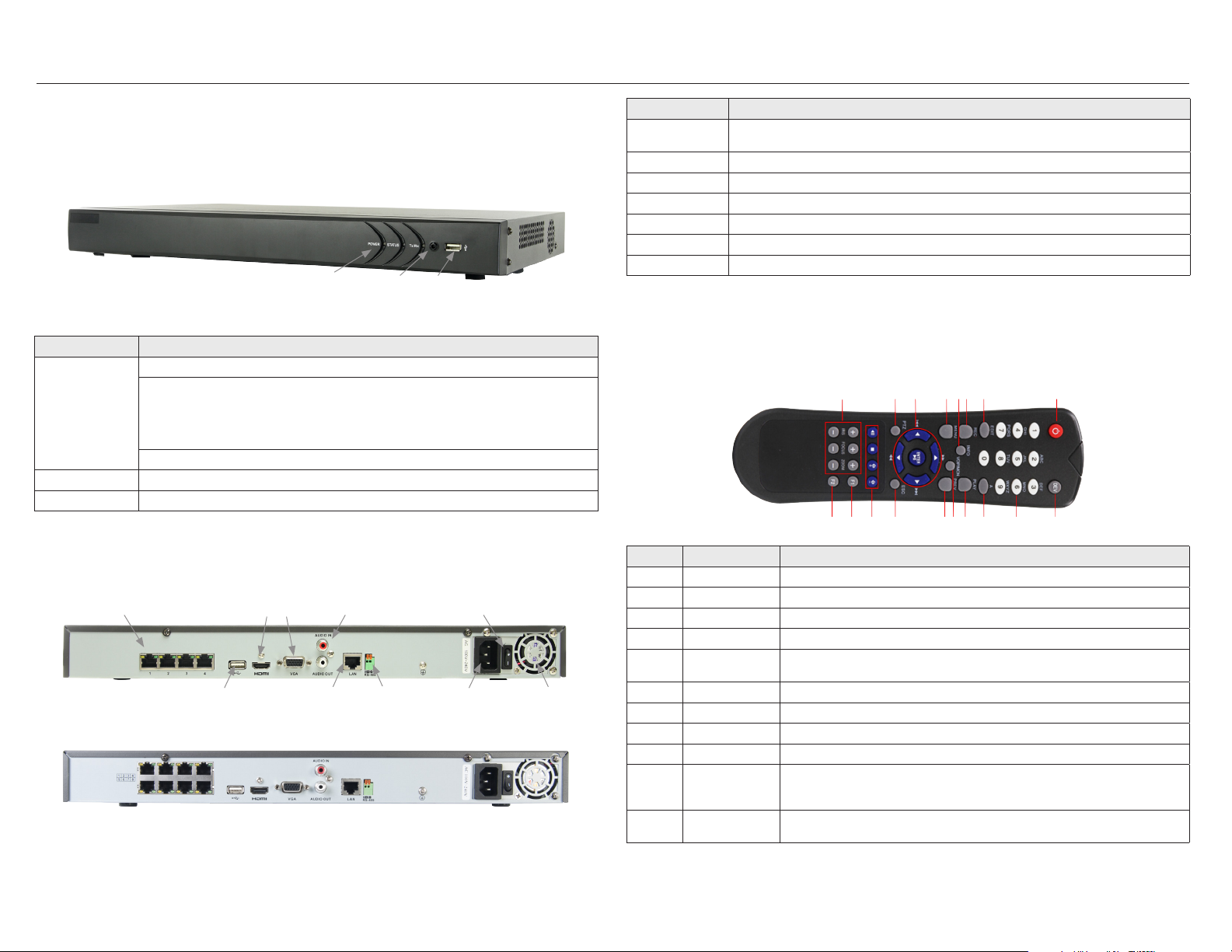
NVR8040, NVR4020 front panel
Item Usage
LED indicators Power: T he POWER indic ator turns gre en when NVR is power ed on.
Status:
1. The light i s green when the I R remote control i s enabled
2. The light is re d when the func tion of the com posite keys (SHIF T) are used
3. The light is ou t when none of the a bove conditio n is met
Tx/ Rx: TX /RX indicato r ickers gree n when the netw ork connec tion is func tioning norma lly.
Infrared Sensor Sensor f or the remote cont rol.
USB port This por t can be used f or a portabl e mobile HDD, ash dri ve, DVD burner, or mou se. An addition al USB port is lo cated on the bac k panel.
IR Sensor
USB port
Item Description
Camera (CH1 - CH 4) Netwo rk interfac e for IP cameras s olely dedica ted to the NVR. Th ese cameras c an only be access ed through th e NVR. Each por t provides
Monitor O ut (HDMI, VGA) HDMI and DB15 (VG A) connector f or monitor.
AUDIO IN / OUT Not func tional. Inclu ded for fut ure expansio n.
ON / OFF switch Switch for p owering the NV R on and o
USB This por t can be used f or a portabl e mobile HDD, ash dri ve, DVD burner, or mou se. An addition al USB port is lo cated on the fr ont panel.
RS-485 terminations Not func tional. Inclu ded for futu re expansion .
Power connector Connec tor for stand ard 3-prong pow er cable.
Power over Eth ernet (PoE) po wer to the device co nnected to i t. NOTE: Only 3SVisio n IP cameras can b e attache d to these channe ls.
Remote Control
The enter key on the remote control or the front panel has the same funct ion as a mouse left click. T he IR Range of the remote control is 10
meters. The bu ttons on the remote control correspond with t he buttons on the front panel.
1213 10
11141518 16
6 4
9177 5
18
23
NVR Backpanel
Camera (CH1 - CH4)
1
USB
ON / OFF switchMonitor Out (HDMI, VGA) Audio IN / OUT
LAN RS-485 Power connector Fan outlet
NVR4020 backpanel
NVR8040 backpanel
Item Name Function
1 POWER Power on/o the d evice.
2 DEV Enables/Disables Remote Control.
3 Alphanumeric Buttons Use for entering numerical data
4 EDIT Button Delete ch aracters b efore curso r, check the chec kbox and selec t the ON/OFF s witch, star t/stop recor d clipping in playb ack
5 A Butto n Adjust fo cus in the PTZ Con trol menu, also u sed to switch b etween inpu t methods (uppe r and lowercase al phabet, sym bols
and numer ic input).
6 REC Button Open the manual record interface
7 PLAY Button Playback , for direct a ccess to playbac k interface.
8 INFO But ton Reserved.
9 VOIP/MON button Switch be tween main and sp ot output. In P TZ Control mod e, it is used to zoo m out the image.
10 MENU button Press t he button wil l help you return t o the Main menu (af ter successf ul login).
Press and h old the butt on for 5 seconds t o turn o audible k ey beep.
In PTZ Cont rol mode, the MEN U/WIPER but ton will star t wiper (if appli cable).
11 PREV but ton Switch betwee n single scree n and multi-sc reen mode.
In PTZ Cont rol mode, it is us ed to adjust the f ocus in conjunc tion with th e A/FOCUS+ bu tton.
NVR4020-8040_SQ
9/20 /13
Page 2
Item Name Function
12 DIRECTION/ENTER
buttons
13 PTZ button Ent er the PTZ Contro l mode (if applic able).
14 ESC button Ret urn to the prev ious menu.
15 RESERVED Reser ved for futu re usage.
16 F1 button Selec t all items on the lis t when used in a lis t eld.
17 PTZ Control buttons But tons to adjust th e iris, focus an d zoom of a PTZ came ra.
18 F2 button Cycle throu gh tab pages.
DIRECT ION: These bu ttons are use d to navigate bet ween diere nt elds and item s in menus.
In the Playb ack mode, the Up an d Down butto ns are used to spe ed up and slow down r ecorded vide o. The Left an d Right
butto n select the n ext and prev ious record le s.
In Live Vie w mode, these bu ttons can be u sed to cycle th rough channels .
In PTZ cont rol mode, they c an control the mo vement of the PTZ c amera.
ENTER: T he ENTER but ton is used to con rm select ion in any of the menu m odes.
It can also b e used to tick ch eckbox eld s.
In Playbac k mode, it can be us ed to play or paus e the video.
In single -frame Playba ck mode, press ing the butto n will advance the v ideo by a single f rame.
In Auto-s witch mode, it c an be used to st op /start auto s witch.
In the PTZ Co ntrol mode, it i s used to adjust t he iris of the PT Z camera.
Press fo r Arming/disar ming the device i n Live View mode.
In PTZ Cont rol mode, it will t urn on/o PTZ light (i f applicable).
In Playbac k mode, it is used t o switch bet ween play and reve rse play.
In synch ronous playbac k mode, use to sw itch betwe en channels.
Mouse Control
A standard 3-bu tton (left/right /scroll-wheel) USB mouse can also be used with this NVR. When the mouse is plugged into the NVR, it is
automatically detected. If t he mouse is not detected, the mouse may not be compatible with the NVR. Please refer to the recommende d
device list from your provider. The but tons on the mouse funct ion as shown in the table below.
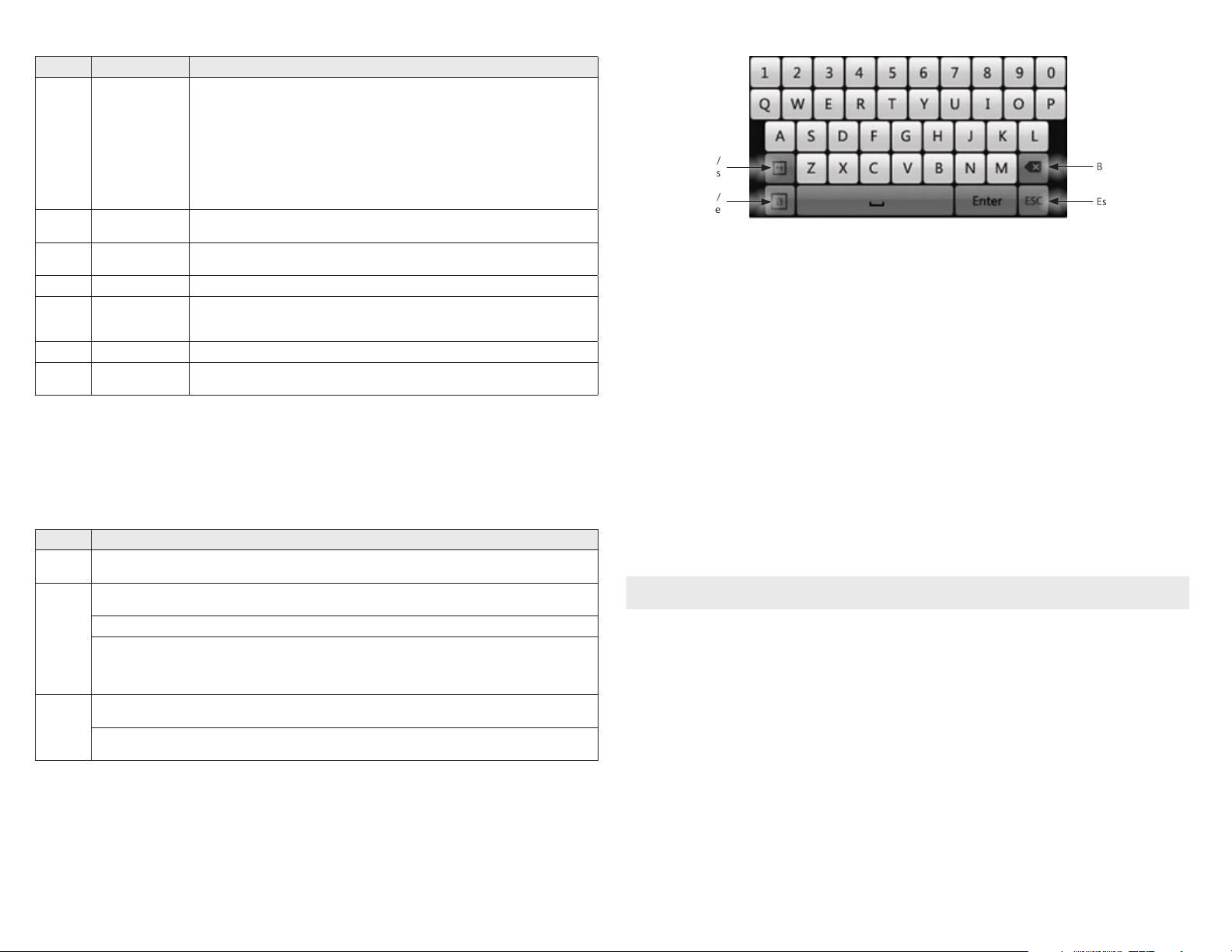
Symbols /
Numbers
Uppercase /
Lowercase
Backspace
Escape / E xit
Soft keyboard
Step 1. Install the NVR and monitor
For the following steps, refer to the back panel photo above for the location of connec tors.
1. Place the NVR in a location that is secure, well ventilated and clean. The NVR should be positioned such that the back panel conne ctors
are accessible and the ventilation holes on the sides and top and the fan outlet on the back are not blocked.
2. Install and setup your monitor in accordance with the instruc tions provided with the monitor. Do not power it on at this time.
3. Cable the HDMI or VGA connector to your monitor ’s VGA or HDMI input. The HDMI interface provides the best perf ormance.
4. Plug the mouse into the USB connec tor on the front or back of the NVR .
5. To access your NVR remotely, or congure your NVR to transmit alerts, email, etc. to external server s, plug a drop cable from your local
area network (LAN) into the RJ45 LAN connec tor on the back of the NVR.
Action Eect
Right click
Left c lick
Scroll wheel
Live view: Show menu.
Menu: Ex it current menu t o upper level menu .
Single click: Live vie w: Select ch annel and show the q uick set menu.
Menu: Sele ct and enter.
Double click: Live vie w: Switch bet ween single- screen and mult i-screen.
Click and drag: PTZ control: pan, t ilt and zoom.
Tamper-proo f, privacy mask a nd motion dete ction: Sele ct target area .
Digital zoom-in: Drag and select target area.
Live view : Drag channel/ time bar
Scrol l up: Live view: Previous screen.
Menu: Previous item.
Scrol l down: Live vie w: Next scr een.
Menu: Nex t item.
1.1.1 Soft keyboard
An on-screen QUERTY keyboard appears when you c lick in a eld that accept s a text entry, such as a password or name. The keyboard is
shown in the following picture. Some control keys toggle their func tion when they are clicked.
2 www.Observint.com
6. Connect the power cord to the p ower connector on the back panel of the NVR, and then into a UP S (preferred) or surge protec tor.
NOTE
Do not power on th e NVR at this time.
Step 2. Install cameras
The camera channel (RJ45) connec tors on the back of the NVR support 3SVision brand IP cameras only. If the cameras you attach to the back
panel were used on another system, they should rs t be reset to the factor y default conguration before connec ting them to the NVR. These
cameras can be au tomatically added to and congured by the NVR system when the NVR is congured.
To prepare your cameras for use with the NVR, do the following:
1. Install your 3SVision IP cameras as nee ded to support your security requirements. Always refer to the documentation prov ided with
the camera for installation instructions.
2. Connect an Ethernet drop c able between each camera and an RJ45 camera channel connec tor on the back of the NVR.
3. Apply power to the cameras and allow at least 3 minutes for them to fully init ialize.
© 2013 Observint Technologies, Inc. All rights reserved.
Page 3

Step 3. Using the Wizard for basic configuration setup
1. Power on the NVR. When the NVR is powered on, an “Embedded NVR ” splash screen appears within 2 minu tes.
By default, t he Setup Wizard opens when the NVR has powered on. The Setup Wizard c an assist you in making import ant
conguration se ttings in NVR.
4. Click the Next button to enter the date and time se ttings window.
2. Click Next button on the Wizard window to open the Login window.
3. Enter the admin password in the appropriate eld. The default admin password is 12345. To change the admin password, che ck the
New Admin Password checkbox, then enter the new password in the New Password and Conrm elds.
3 www.Observint.com
5. In the date and time setup window, click the eld you want to change, then use the drop-down list or setup aid to select the
appropriate values. Click Next to conrm your settings or Cancel to discard them and open the net work setup Wizard window.
In the network setup Wiz ard window, click the eld value you want to change, then use t he pop-up aid to enter a new value.
Congure the internal NIC IPv4 Address for the cameras connecting to the Camera c hannel ports on the back panel of the NVR.
NOTE: The IPv4 Address and the Internal NIC Pv4 Address must be on dierent networks (subnets).
© 2013 Observint Technologies. All rights reserved.
Page 4
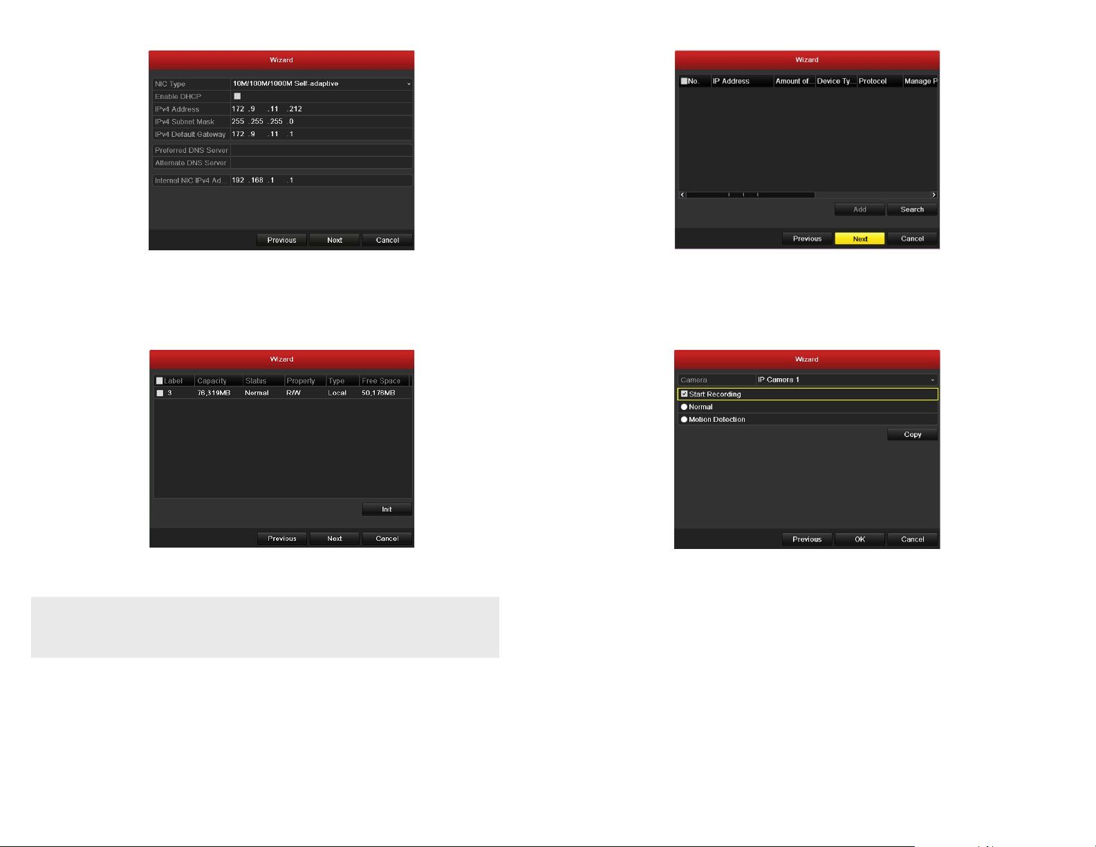
6. Click Next after you congured the net work parameters. The HDD management Wizard window will open.
9. Use the camera record mode Wiz ard as follows:
7. To initialize an HDD, click the check box for the device you want to initialize, click the Init button, then follow the on-s creen
instruc tions to complete the process. NOTE: Initialization removes all the data save d on the HDD. Click Next to continue.
8. In the add IP Camera Wizard, click Nex t.
You can add additional I P cameras compatible with the NVR that are ac tive on the local LAN the NVR is networked to. Howe ver,
NOTE
these additio nal cameras, plus the cameras in use by the NVR that are at tached to the RJ45 connectors on the back panel, cannot
exceed the channel cap acity of your system: 4 channels with th e NVR4020 or 8 channels with th e NVR8040. See “APPENDIX C
Adding Cameras on the L AN to the NVR” on page <?> for procedural guidelin es on adding these cameras.
a. On the Cameras line at the top of the window, open the drop-down list and select the camera you want to congure for
recording.
b. Select one of the recording modes: click Start Recording, then select either Normal (continuous) or Motion Detection
mode.
c. Repeat “a” and “b” above for each camera, and/or click Copy to copy the recording mo de of the selected camera to ot her
cameras in the system.
4 www.Observint.com
© 2013 Observint Technologies. All rights reserved.
Page 5

d. Click OK when the recording mode for each camera is selected. The Wizard will clos e and the NVR will present the Live View
dis play.
Step 4. Using the Menu system
After the initial setup of your NVR using the Wizard, the Menus interface enables you to re ne your conguration settings and expand the
functionality of the s ystem. To use most menus, the user must log into the NVR system, either loc ally or remotely, with administrative
privileges.
To open the Menu system f rom the Live View screen, right click anywhere in the screen, then select Menu
Click Menu to open the menu system. A login window will open. In the Login window, selec t a User Name with administrative pr ivileges,
enter its pass word, then click OK. A window of Menu icons will op en.
Live View display
10. While viewing video from each cameras in the Live View display, adjust the dire ction of each camera to aim it at it s surveillance
target. Follow the manufacturer’s recommended procedures for aiming the cameras.
5 www.Observint.com
For additional information about using your system, refer to the NVR4020, NVR8040 Embedded Net work Video Recorder User Manu al
provided on CD with your system.
© 2013 Observint Technologies. All rights reserved.
Page 6

Specications
Model NVR4020 NVR8040
Number of C hannels Suppor ted 4 8
Compression Format H.264
Recording Performance 20 Mbps ma x
Remote Viewing Output Capacity 60 Mb ps max
Rec ordin g Type Continuous, Schedule, Motion Detection
Supported IP Camera Resolution 5MP/3MP/1080p/UXGA/720p/VGA/4CIF/DCIF/2CIF/CIF/QCIF
Supported Playback Resolution 5MP/3MP/1080p/UXGA/720p/VGA/4CIF/DCIF/2CIF/CIF/QCIF
Synchronous Playback 4 -ch, 720P / 2-ch, 10 80P / 1-ch, 5MP 8-ch, 4 CIF / 4-ch, 720 P / 2-ch, 1080P / 1-ch, 5M P
Video Output VGA, HDMI
Export Formats .MP4
Ethernet 1x Gigabit R J-45 self-ad aptive Ethern et interfa ce, 4 independen t 10 /100 Mbps PoE Ether net interf aces
USB 2x USB 2.0
Operating System Embedded Linux
Security Password Protection
Protocols IPv4, TCP/IP, UDP, HTTP, UPnP, RTSP/RTP/RTCP, SMTP, FTP, DHCP, NTP, DNS, ONVIF, HTTP mu ltipart
Supported IP Camera Brands 3S Vision
Power Requirements 110-240 Vac
Power Consumption 3A
Weight 5.5 lbs. (wit hout HDD)
Dimensions (in.) 1.77" (H) x 17.52" (W) x 11.42" (D)
Operating Temperature 14°F ~ 131°F
Color / Material Black, Gray
Material Aluminum
Approvals CE, FCC, Ro HS
Remote Client System Requirements
Operating System Microso ft Windows 2 000, 2003, XP, Vista, 7, 8 (32-bit and 64 -bit versio n) / Linux 2.6+ / Apple M acOS X 10.5 (Intel x8 6 only), 10.6
Web Browser Microsof t Internet E xplorer 8.0, 9.0, an d 10 (32-bit version), Mozill a Firefox 13 and highe r and 3.6,
Software Requirement s Web Component Installation
Mobile Client OS Platform iOS, Android (Guarding Expert)
and 10.7
Safari 5 a nd higher, Google C hrome
6 www.Observint.com
© 2013 Observint Technologies. All rights reserved.
 Loading...