

Page 1
N4, N8, N16, N32 Embedded Network Video
Recorder User Manual
Products: N4, N8, N16, N32 Network Video Recorders
PLEASE READ THIS MANUAL BEFORE USING YOUR SYSTEM, and always follow the instructions for safety
and proper use. Save this manual for future reference.
RS_N4-8-16-32_V8.1.0_RM
190 312
Page 2

About this manual
This manual suppor ts the N-series Net work Video Recorders (NVR s). It describes usage of the startup Wizard, and the parameters
used in the embe dded rmware screens. It also includes a basic approach to accessing the NVR across an Ether net network and via
the smartphone app HDVision Mobile.
LEGAL NOTICE
Observint Technologies (Observint) products are designed to meet safety and performance standards with the use of
specic Observint authorized accessories. Observint disclaims liability associated with the use of non-Observint
authorized accessories.
The recording, transmission, or broadcast of any person’s voice without their consent or a court order is strictly
prohibited by law.
Distributing, copying, disassembling, reverse compiling, reverse engineering, and exporting, in violation of
export laws, the software provided with Alibi video recorders is expressly prohibited.
Observint makes no representations concerning the legality of certain product applications such as the making,
transmission, or recording of video and / or audio signals of others without their knowledge and / or consent.
We encourage you to check and comply with all applicable local, state, and federal laws and regulations before
engaging in any form of sur veillance or any transmission of radio frequencies.
Microsoft, Windows, and Internet Explorer are either registered trademarks or trademarks of Microsoft Corporation in
the United States and / or other countries. Android is a trademark of Google Inc. Use of this trademark is subjec t to
Google Permissions. Apple, iPhone, iPod to uch, and iPad are registered trademarks of Apple Inc.
Other trademarks and trade names may be used in this document to refer to either the entities claiming the marks
and names or their products. Obser vint disclaims any proprietary interest in trademarks and trade names other than
its own.
No part of this document may be reproduced or distribute d in any form or by any means without the express writ ten
permission of Observint Technologies.
© 2019 by Observint Technologies. All Rights Res erved.
15505 Long Vista Dr, Suite 250, Austin, TX 78728
For Sales and Support, please contact your distributor.
ii
www.Observint.com
Page 3

TABLE OF CONTENTS
Table of Contents
SECTION 1 Systems Overview ...................................................................1
1.1 Using the mouse .....................................................................3
SECTION 2 Initial Setup ........................................................................6
2.1 Activation ...........................................................................6
2.2 Using the Wizard for initial conguration ................................................8
SECTION 3 Channel - Live Display ..............................................................19
3.1 Live display ........................................................................19
3.2 Live View screen controls .............................................................23
3.2.1 Channel - Live screen ............................................................23
3.2.2 Channel - Channel menu ........................................................23
3.2.3 Channel - Protocol Manage menu .................................................24
3.2.4 Channel - Live menu ............................................................25
3.2.5 Channel - Image Control menu ...................................................27
3.2.6 Channel - PTZ menu ............................................................28
3.2.7 PTZ control panel ...............................................................28
3.2.8 Channel - Privacy Mask menu ....................................................29
3.2.9 Channel - Motion menu .........................................................30
3.2.10 PIR ...........................................................................32
SECTION 4 Record ...........................................................................35
4.1 Encode ............................................................................35
4.2 Record ............................................................................36
4.2.1 Record Schedule ................................................................37
SECTION 5 Alarm Conguration ...............................................................39
5.1 Motion alarm handling ..............................................................39
5.2 PIR. . . . . . . . . . . . . . . . . . . . . . . . . . . . . . . . . . . . . . . . . . . . . . . . . . . . . . . . . . . . . . . . . . . . . . . . . . . . . . . .40
5.3 IO alarm menu .....................................................................41
5.4 PTZ Linkage alarm menu .............................................................41
5.5 Exception ..........................................................................43
SECTION 6 Network Conguration .............................................................44
6.1 General settings ....................................................................44
6.1.1 PPPoE settings .................................................................45
6.1.2 Port Conguration ..............................................................46
6.2 DDNS settings ......................................................................46
iiiN4, N8, N16, N32 NVR V8.1.0 User Manual
Page 4

TABLE OF CONTENTS
6.3 Email setup ........................................................................48
6.3.1 Email Schedule .................................................................49
SECTION 7 Device Conguration ...............................................................50
7.1 Disk ...............................................................................50
7.1.1 Disk Group ....................................................................52
7.1.2 S.M.A.R.T. data .................................................................52
7.2 Cloud settings ......................................................................53
SECTION 8 System Settings ...................................................................55
8.1 General settings ....................................................................55
8.1.1 Date and Time .................................................................55
8.1.2 Output Conguration ...........................................................58
8.2 Multi-User setup ....................................................................60
8.3 Maintenance .......................................................................64
8.3.1 Log ...........................................................................65
8.3.2 Load Default ...................................................................66
8.3.3 Upgrade ......................................................................67
8.3.4 Parameter Management ........................................................67
8.3.5 Auto Reboot ...................................................................69
8.4 IP Camera Maintain .................................................................69
8.4.1 Upgrade ......................................................................69
8.4.2 Load Default ...................................................................70
8.4.3 Reboot IPC ....................................................................71
8.5 Information ........................................................................71
8.5.1 Channel Information ............................................................72
8.5.2 Record Info ....................................................................72
8.5.3 Network Status .................................................................73
SECTION 9 Search, Playback, Backup and Tags ...................................................74
9.1 Using Search Features ...............................................................74
9.1.1 Search, Playback and Backup video ................................................75
9.1.2 Event Search, Playback and Backup ................................................78
9.1.3 Event Playback Control ..........................................................79
9.1.4 Sub-periods Playback ...........................................................80
9.1.5 Smart Search and Playback ......................................................81
9.1.6 Smart Search Area ..............................................................81
9.1.7 Tags ..........................................................................83
iv
www.Observint.com
Page 5

TABLE OF CONTENTS
SECTION 10 Remote Login .....................................................................87
10.1 System Requirements ...............................................................87
10.2 Remote login .......................................................................87
10.2.1 Remote login with Surveillance Plugin installation ..................................88
10.3 Live screen .........................................................................90
10.4 Playback screen .....................................................................92
10.5 Remote Settings ....................................................................93
10.6 Local Settings ......................................................................94
SECTION 11 HDVision Mobile App for Remote Access ...............................................95
11.1 Getting Started .....................................................................95
11.2 Help screens. . . . . . . . . . . . . . . . . . . . . . . . . . . . . . . . . . . . . . . . . . . . . . . . . . . . . . . . . . . . . . . . . . . . . . . .97
11.2.1 Overview .....................................................................97
11.2.2 Live (View) ....................................................................98
11.2.3 (Remote) Playback .............................................................98
11.2.4 Record (Local Playback) .........................................................99
11.2.5 Image (Manager) ...............................................................99
11.2.6 Remote Setting ...............................................................100
11.2.7 Alarm .......................................................................100
11.2.8 Device (Manager). . . . . . . . . . . . . . . . . . . . . . . . . . . . . . . . . . . . . . . . . . . . . . . . . . . . . . . . . . . . . .101
SECTION 12 Using Video Player Software ........................................................102
12.1 Installation on Windows ............................................................102
12.2 Play video le .....................................................................104
12.2.1 Capture image ................................................................105
12.2.2 Save clip .....................................................................106
APPENDIX A Troubleshooting ..................................................................109
A.1 System troubleshooting ............................................................109
A.2 Best Practices .....................................................................111
vN4, N8, N16, N32 NVR V8.1.0 User Manual
Page 6

NOTES
vi
www.Observint.com
Page 7

SECTION 1: SYSTEM OVERVIEW
SECTION 1
Systems Overview
Congratulations on purchasing your new Embedded NVR s ecurity system! Your system includes the following key features:
General
• Connectable to network cameras, network dome and encoders
• Connectable to third-par ty network cameras that are ONVIF compat ible (includes Alibi)
• Connectable to smar t IP cameras
• H.265 / H.264 video formats
• PAL / NTSC adaptive video inputs
• Each channel supports dual-stream
• Up to 4 / 8 / 16 / 32 network cameras can be added to the recorder up to the c apacity of the NVR.
• Independent conguration for each c hannel, including resolution, frame rate, bit rate, image qualit y, etc.
• The quality of the input and outpu t record is congurable
Local Monitoring
HDMI / VGA outputs provided
• HDMI video output at up to 4K resolution
• Multi-scre en display in live view is supported, and the display sequence of channels is adjustab le
• Live view screen can be switched in groups. Manual s witch and auto-switch are prov ided and the auto-switch inter val is
congurable
• Custom window-division live view layout conguration
• 3D positioning in live view
• Congurable main st ream and sub-stream for the live view
• Quick setting menu is provide d for live view
• Motion detec tion, video tampering, vide o exception alert and video loss alert functions
• Privacy mask
• Support s Pelco D, Pelco P, presets and cruise
• Zooming in by clicking the mouse and PTZ t racing by dragging mouse
HDD Management
• N4, N8 and N16 support 1 internal SATA HDD, N32 supports up to 4 inter nal HDDs and 1 eSATA devices
• Up to 8 TB storage capacity for each disk suppor ted (refer to the specications for your recorder for hardware c apabilities)
• S.M.A.R.T. and bad sector detection
• HDD group management
• Supports HDD standby function
• HDD property: redundancy, read-only, read / write (R / W )
1N4, N8, N16, N32 NVR V8.1.0 User Manual
Page 8

SECTION 1: SYSTEM OVERVIEW
• HDD quota management; dierent capacit ies can be assigned to dierent channels
• Disk clone to the eSATA disk
• HDD health monitoring
Recording, Capture and Playback
• Continuous and event video recording parameters
• Multiple recording types: manual, continuous, alarm, motion, IO
• Pre-record and post-record for alarm, motion dete ction for recording, and pre -record time for schedule and manual recording
• Searching record le s and captured pictures by events (alarm input / motion detection)
• Tag adding for record les, searching and playing back by t ags
• Locking and unloc king record les
• Local redundant recording
• Normal / Smart / Tag video playback mode
• Searching and playing back record les by channel number, recording type, start time, end time, etc.
• Support s playback by main stream or sub stream
• Smart search for the selec ted area in the video
• Zoom in during playbac k
• Reverse playback of multi-channel
• Support s pause, play reverse, speed up, speed down when playback, and locating by dragging the mouse
• Support s thumbnails view and fast view during playback
• Up to 16-ch synchronous playback at 1080p real time. See sp ecications for you NVR
• Support s playback by transcoded stream
• Manual capture, continu ous capture of video images and playb ack of captured pictures
Files Management
• Search and export vehicle detection le s and human appearance les
• Expor t video data by USB or eSATA device
• Expor t video clips during playback
• Alarm and Exception
• Congurable arming time of alarm input / ou tput
• Alarm for illegal login, network disconnecte d, HDD error, and HDD full
• Alarm trigger s full screen monitoring, audio alar m, sending e-mail and alarm output
Other Local Functions
• Operable by mous e, remote control, or control keyboard
• Two-level user management; admin user is allowed to c reate many operating accounts and dene their operating p ermission,
which includes the limit to access any channel
• Admin password re setting by expor ting / importing a system conguration le
• Operation, alarm, exceptions, and log re cording and searching
2
www.Observint.com
Page 9

SECTION 1: SYSTEM OVERVIEW
• Manually triggering and clearing alarms
• Import and export device conguration information
Network Function
• Self-adaptive 10M / 100M / 100 0 Mbps network interf ace
• TCP/IP protocol, DHCP, DNS, DDNS, NTP, SADP, SMTP, NFS, and iSCSI are supp orted
• TCP, UDP and RTP for unicas t
• Auto / Manual port mapping by UPnPTM
• Remote Web browser access by HTTPS ensure s high security
• Remote reverse playback via RTSP
• Support s accessing the platform via ONVIF
• Remote search, playback , download, locking and unlocking of the record les, and support s downloading les upon broken
transfer resume
• Remote parameters setup; remote import / export of device parame ters
• Remote viewing of the device status, system logs and alarm status
• Remote keyboard operation
• Remote HDD format ting and program upgrading
• Remote system restart and shutdown
• RS-485 tr ansparent channel transmission
• Alarm and exception information can be sent to the remote ho st
• Remotely start / s top recording
• Remotely start / s top alarm output
• Remote PTZ control
• Remote JPEG capture
• Two-way audio and voice broadcasting
• Embedded Web server
1.1 Using the mouse
Mouse control
A standard 3-bu tton (left / right / scroll-wheel) USB mouse can also be used with this NVR. To use a USB mouse:
1. Plug the USB mouse into the either the front panel or back panel USB connector of the NVR.
2. When the recorder is powered on, the mouse will be automatically detected. If the mouse is not detected, the mou se may not
be compatible with the NVR. Please refer to the recommended device lis t from your provider.
3N4, N8, N16, N32 NVR V8.1.0 User Manual
Page 10
SECTION 1: SYSTEM OVERVIEW
Using the mou se
1. Left But ton:
— Click to select menu options.
— During live viewing in split-screen view, double-click on a channel to view it in full-screen. Double- click the channel
again to return to split-screen viewing.
— Click upon a channel on Live Viewing screen to open Camera Quick Toolbar.
— Click and hold to drag sliders and scales on menu mode
2. Right Button:
— Click once to open the task bar on the Live Viewing sc reen.
— In menus, click to go back or close t he menu.
3. Scroll Wheel:
— In menus, scroll to move up / down through the menu content.
— While hovering over the volume control wheel, scroll to turn system volume up / down.
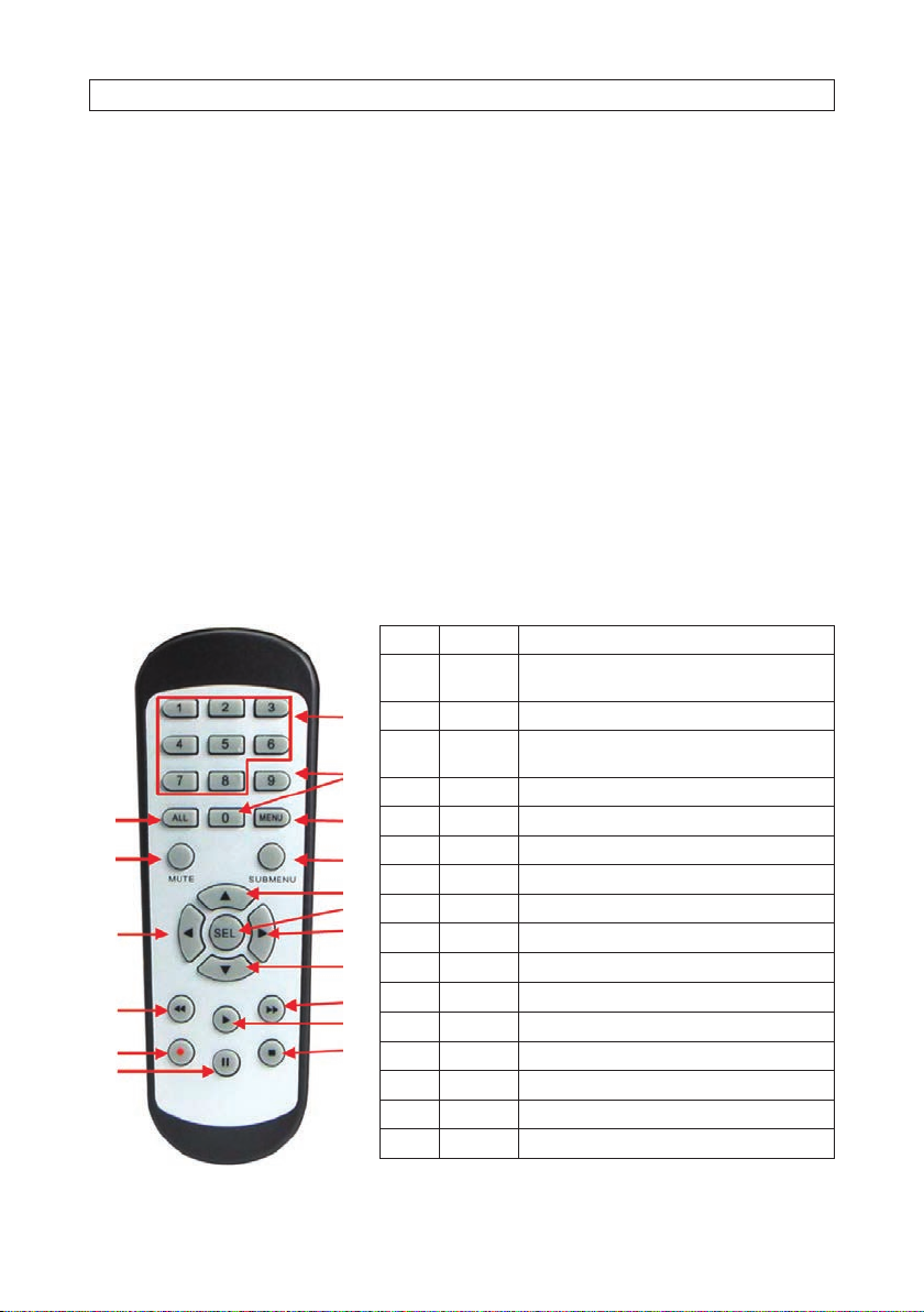
Using the Remote Control
No. Icon Description
1 1-8
2 9, 0 Numeric keys
1
3 ALL
2
4 Menu Press t o enter or exit th e Main Menu
3
5
9
11
14
16
4
5 Mute Mute On/o
6 Submenu Go to subme nu
6
7
7
8
9
10
12
13
15
8 SEL Pre ss to enter the sel ected menu it em and edit the se tting
9
10
11
12
13
14 Press to s tart manual re cording
15 Press to s top manual recor ding or stop the v ideo playbac k
16 | | Press to p ause the video p layback or enter f rame-play back mode
Numeric keys
Press to di splay channel 1~8
Press to di splay all channels
Multiple d isplay mode
Up arrow key ; Volume increase
Left /Right key; De crease/incr ease paramet er value of contro l bar.
Down arr ow key; Volume decre ase
Press to re wind during vi deo playback
Press to f ast forwa rd during video p layback
Press to pl ay recorded vid eo or enter the re cording search m enu
4
www.Observint.com
Page 11
SECTION 1: SYSTEM OVERVIEW
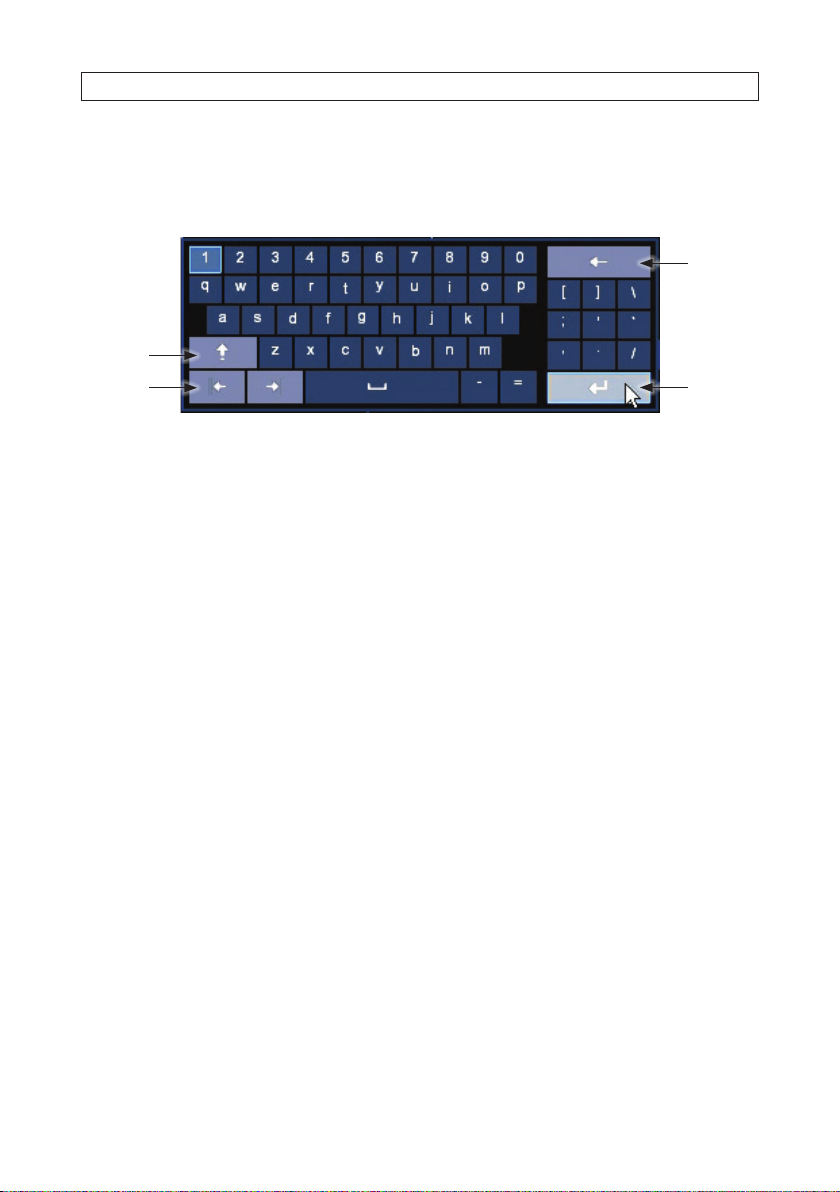
Using the Virtual Keyboard
When you click in an editable data entr y eld, a virtual keyboard will app ear. Click on the charac ter in the keyboard to enter it into
the eld. When the dat a entry is complete, click the Enter key in the lower right corner.
Click to
delete
previous
character
Click for
upp er,
lower case
Move cursor
left, right
Enter
5N4, N8, N16, N32 NVR V8.1.0 User Manual
Page 12
SECTION 2: INITIAL SETUP
SECTION 2
Initial Setup
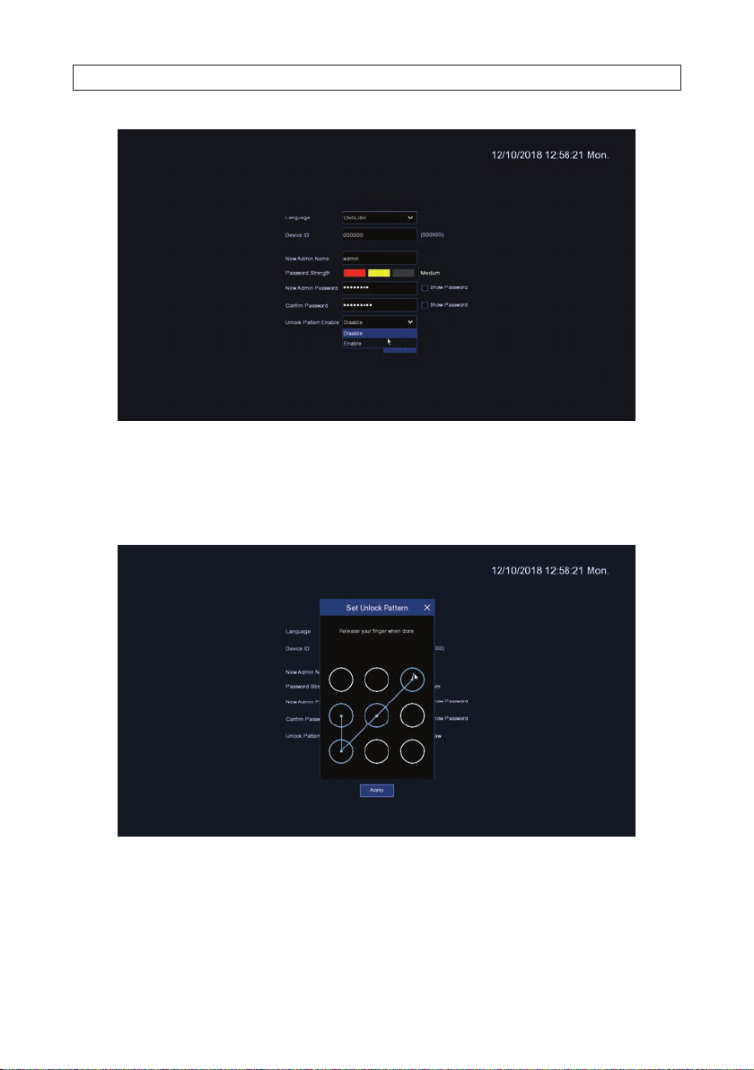
When the NVR is rs t powered on, it must be activated. Activation sets the admin user password and a Lock Pattern if used.
After Activation, you can use the Wizard to setup the basic conguration of the s ystem, including network parameters, time,
cameras, etc.
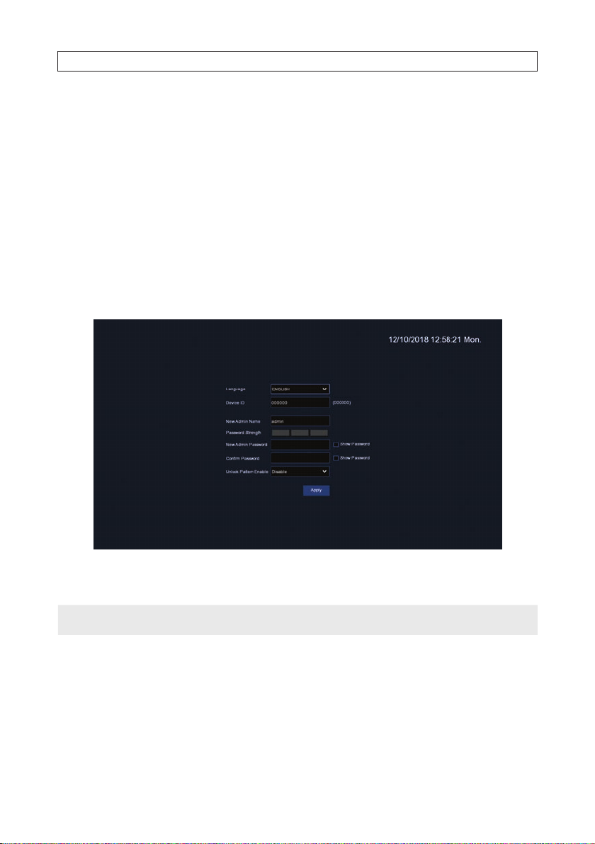
2.1 Activation
When the NVR powers on, a “SYSTEM INITIALIZING” splash sc reen normally appears within 3 minutes. If it is the r st time
powering on the re corder, an activation screen will op en. You must use this menu to setup an admin password for the system, and
an Unlock Pattern, if preferred, for quickly accessing the conguration menus if the recorder.
1. In the screen shown above, enter your admin password in the New Admin Password and Conrm Password elds (see
below). Ensure that the Password Strength of your password is at least Medium (preferably Stron g).
NOTE
6
If you forget your p assword, you will be unable to logi n the system, please contact your vendo r to reset the password.
www.Observint.com
Page 13
SECTION 2: INITIAL SETUP
2. If you want to use an Unlock Patter n to access the conguration menus, open the Unlock Enable drop down list, and t hen
click Enable. Click Apply to continue.
3. Click the Draw button to open the Set Unlock Pattern window.
4. In the Set Unlock Pattern window, drag the mouse cursor across a patter n of circles, then release the mouse.
5. Repeat the pattern you entered, and then click Apply to save the conguration. The conguration Wizard initial screen will
open.
7N4, N8, N16, N32 NVR V8.1.0 User Manual
Page 14
SECTION 2: INITIAL SETUP
2.2 Using the Wizard for initial conguration
Use the Wizard to setup the basic conguration of your s ystem. Advanced conguration opt ions are available in the Setup menus.
Refer to the rmware user manual (to be provided) for your recorder for more information.
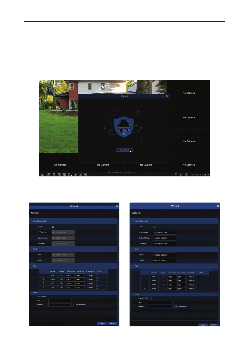
1. When the initial Wizard window appears, click Start Wizard to cont inue.
2. The next Wizard screen is used to con gure the network set tings of the recorder. Initially, the recorder acquires network using
DHCP (Dynamic Hos t Conguration Processor) which usually exist s somewhere on your LAN. DHCP provides network settings
that are compatible with other device s on your LAN.
8
www.Observint.com
Page 15

SECTION 2: INITIAL SETUP
a. It is preferred to have xed network settings instead of dynamic settings, however. To change from dynamic network
settings to xed set tings, copy the settings found through DHCP f or the Local Connection and DNS, uncheck the DHCP
select box near the top of the menu, then re-enter the DHCP Local Connec tion and DNS settings. You can also enter your
own networ k settings for the recorder (these must b e compatible with other devices on the LAN). If you choos e to enter
your own network parameter s, consider the following:
IP Address: The IP address identies the NVR in the network . It consists of four groups of numb ers between 0 to 255,
separated by periods. For example, “192.168.001.100”.
Subnet Mask: Subnet mask is a net work parameter which denes a range of IP address es that can be used in a
network . If IP address is like a street where you live then subnet mask is like a neighborhood. The subnet address also
consists of four groups of number s, separated by periods. For example, “255.255.000.00 0”.
Gateway: This address allows the NVR to access the Internet. The format of the Gateway addre ss is the same as the IP
Address. For example, “192.168.001.001”.
DNS1/DNS2: DNS1 is the primary DNS ser ver and DNS2 is a backup DNS server. Usually should be enough just to enter
the DNS1 server addres s.
b. You can also congure the ports the NVR. If you ne ed to change the port number s of your NVR, consider the following:
Web Port: This is the port that you will use to log in remotely to the NVR (e.g. using the Web Client). If the default port
80 is already taken by other applications, please change it.
Client Port: This is the por t that the NVR will use to send information through (e.g. using the mobile app). If the default
port 90 00 is already taken by other applications, please change it.
RTSP Port: This is the por t that the NVR will be allowed to transmit real-time streaming to other device (e.g. using a
streaming Media player.).
HTTPS: HTTPS is the secure ver sion of HTTP, the protocol over which dat a is sent between your browser and the website
that you are connec ted to. If you want to log in remotely to the NVR using Web Client, you need to complete the port
forwarding in your router. The default port number is 0443.
PPPoE: PPPoE is an advanced protocol that allows the NVR to connect to t he network more directly via DSL modem.
Check the Enable PPPOE box, and then enter the User name and Password of the PPPoE.
c. Click Next to continue.
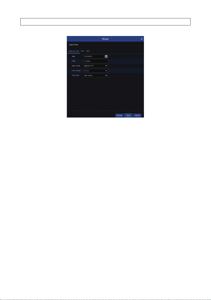
3. Use the Date/Time menu to set the Date, Time, Date F ormat, Time Format, Time Zone, NTP and DST (daylight savings time).
9N4, N8, N16, N32 NVR V8.1.0 User Manual
Page 16
SECTION 2: INITIAL SETUP
a. When changing parameters in the Date and Time tab, consider the following:
Date: Click on the calendar icon to set the sy stem date.
Time: Click to set the system time.
Date Format: Choose from the drop down menu to set preferred date f ormat.
Time Format: Choose time for mat between 24-hour and 12-hour.
Time Zone: Set the correct time zone.
b. Click the NTP tab. To use a Network Time s erver to automatically set the date an d time in your recorder, check the Enable
NTP box, and then select a Server Address from the drop down list. Click Update Now to acquire the current Date and
Time information.
c. Click the DST (Daylight S avings Time) tab. Set up the values in the DST menu to match your local DST custom, if preferred.
10
www.Observint.com
Page 17
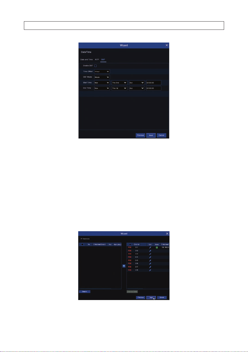
If changing the DST s ettings, consider the following:
DST: Enable if Daylight Saving Time (DST ) is observed in your region.
Time Oset: Select the amount of time to o set for DST
Time Mode: Choose to set the daylight saving time in weeks or in days
Start Time/End Time: Set the start time and end time fo r daylight saving.
SECTION 2: INITIAL SETUP
4. Click Next to continue.
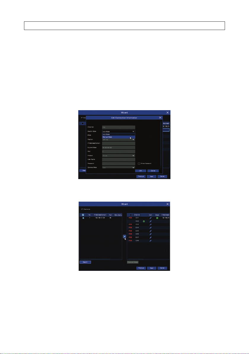
5. In the IP Camera menu, the Wizard automatic ally lists all cameras connected to the channel R J-45 connectors on the back
panel. If some channels are unused, you can add compatible net work IP cameras to the NVR up to the capacity of t he NVR. For
instance, if you have an 8- channel NVR and have four cameras plugged into the backpanel channel connectors, you can add 4
additional IP cameras that are inst alled on the network, for a total of 8.
11N4, N8, N16, N32 NVR V8.1.0 User Manual
Page 18
SECTION 2: INITIAL SETUP
To use this menu:
a. If you are NOT adding network IP cameras to the NVR for monitoring, click Next to continue, and to to the step: “6. In the
Disk menu... on page 13.
b. To add networ k cameras to the NVR for monitoring:
i. Click the icon in the Edit column for a c hannel where a camera is not assigned. In t he example above, channels 2
through 8 are not assigned.
ii. In the Edit Connection Information menu, open the Switch Mode drop down list, and then select Manual
Mode. Click OK to close this menu.
iii. In the IP Camera Wizard window, click the Search button in the lower lef t corner. A list of compatible IP
cameras inst alled on the network will appear in t he left frame.
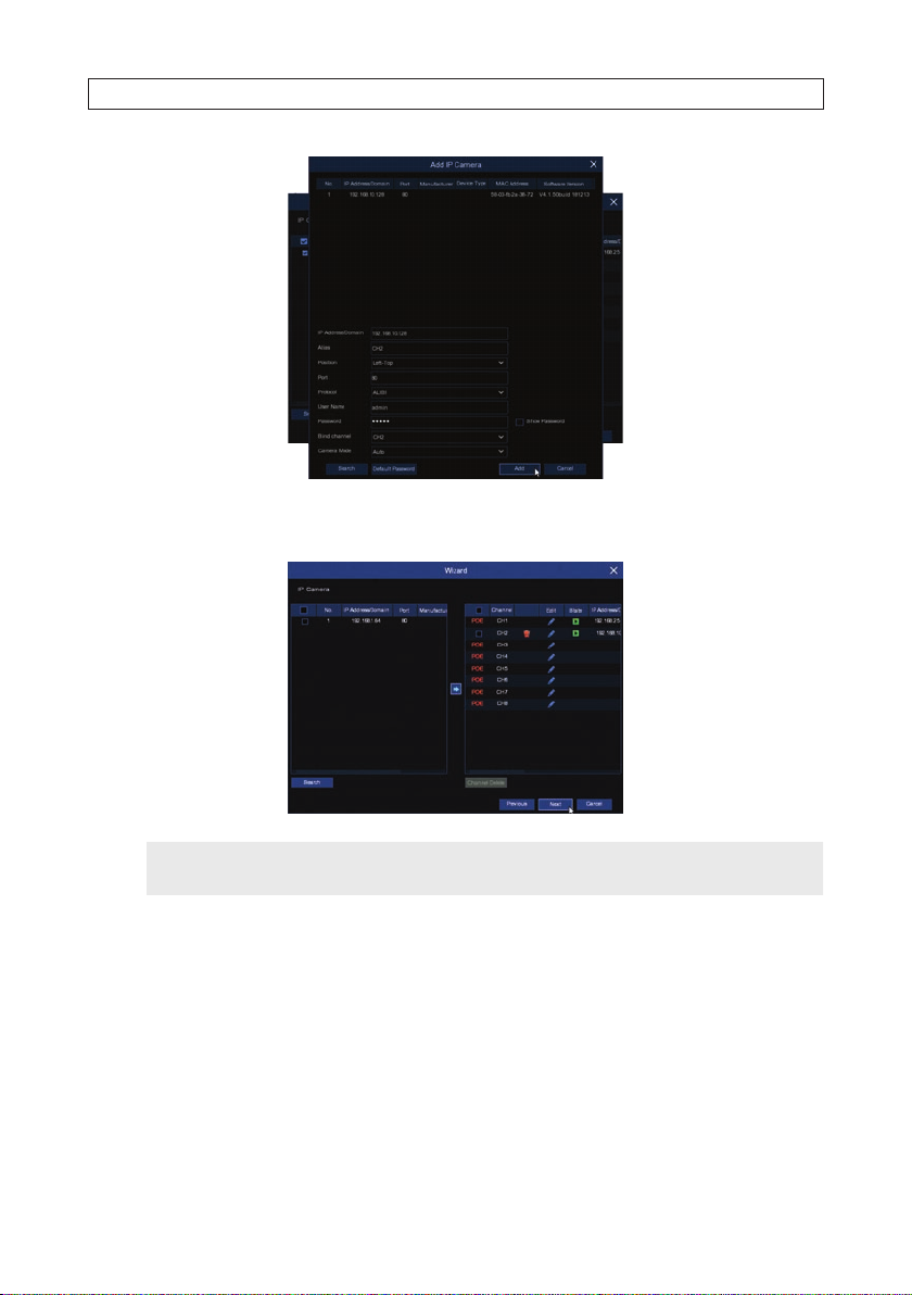
iv. To add a network camera from the search result s list, check the selec t box for the camera you want to add, and
then click the Add bu tton (blue right arrow but ton) in the middle of the window. An Add IP Camera menu will
open.
12
www.Observint.com
Page 19
SECTION 2: INITIAL SETUP
v. The IP Camera menu will open showning the c amera you added listed in the right frame. You can click the icon
for the camera in the State column to s ee live video from the camera.
NOTE
For the camera you added , if the icon in the State column is not green (like tha t shown for CH1 above), click the Edit
icon and correct any pa rameters that are in error before contin uing.
vi. Repeat this procedure to add ad ditional network cameras to you NVR.
vii. Click Next to advance to the nex t Wizard menu.
6. In the Disk menu, you can congure how your disk (HDD) will be used. The Overwrite (Auto) feature enables you to always
keep a previous, opt ional number of days of data written to the HDD when the disk becomes full, and Format initializes the
HDD for use in the recorder and erases all data on the disk . If you installed HDDs in your recorder, it is strongly advised to
format thes e drives before using your recorder.
13N4, N8, N16, N32 NVR V8.1.0 User Manual
Page 20

SECTION 2: INITIAL SETUP
a. To congure the HDD for Overwrite:
viii. Check the select box for the HDD you want to congure from the list above.
ix. Open the Overwrite drop down lis t, and then select Auto.
b. To format an HDD:
i. Check the sele ct box for the HDD you want to Format from the list above.
ii. Click the Format button. Allow the format operation to complete before continuing.
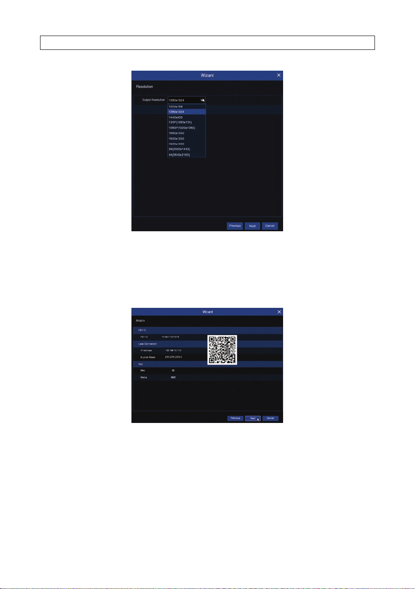
7. Click Next to continue.
Use the Resolution menu to select an outpu t resolution that matches your moni tor. The NVR automatically adjusts the output
resolution during star t up to match the highest resolution of your monitor.
14
www.Observint.com
Page 21
SECTION 2: INITIAL SETUP
8. To change the resolution, open the drop down list, select the re solution you prefer, and then click Apply.
9. Click Next to cont inue.
The Mobile scre en shows the P2P settings provided with your recorder, and a QR code you can scan to easily connect the NVR to the
mobile app HDVision (available free for Android and iOS).
10. Click Next to continue.
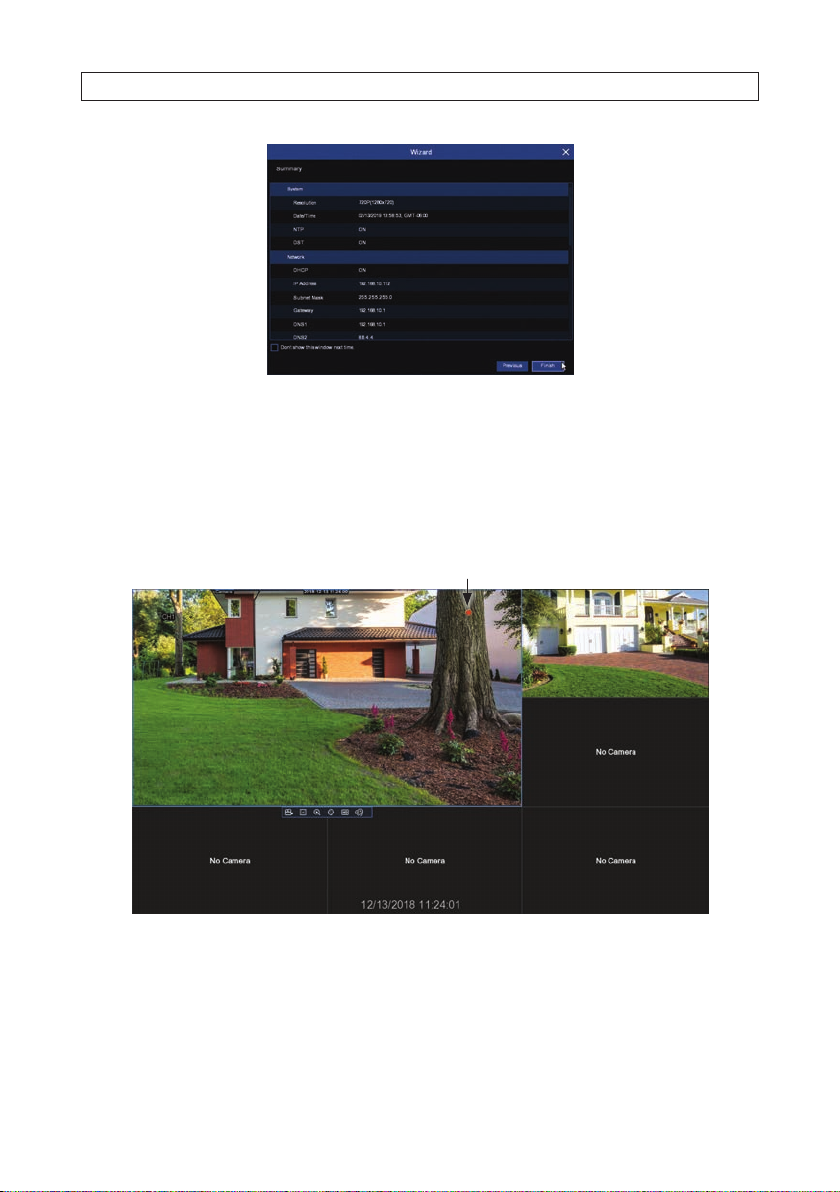
The Summary screen show s the settings selec ted the Wizard.
15N4, N8, N16, N32 NVR V8.1.0 User Manual
Page 22
SECTION 2: INITIAL SETUP
11. In the Summary screen, you can:
— Check the select box to Don’t show this window next time.
— Click Previous to return to the Wizard screens and change your selec tions.
— Click Finish to close the Wizard.
12. Click Finish to close the Wizard.
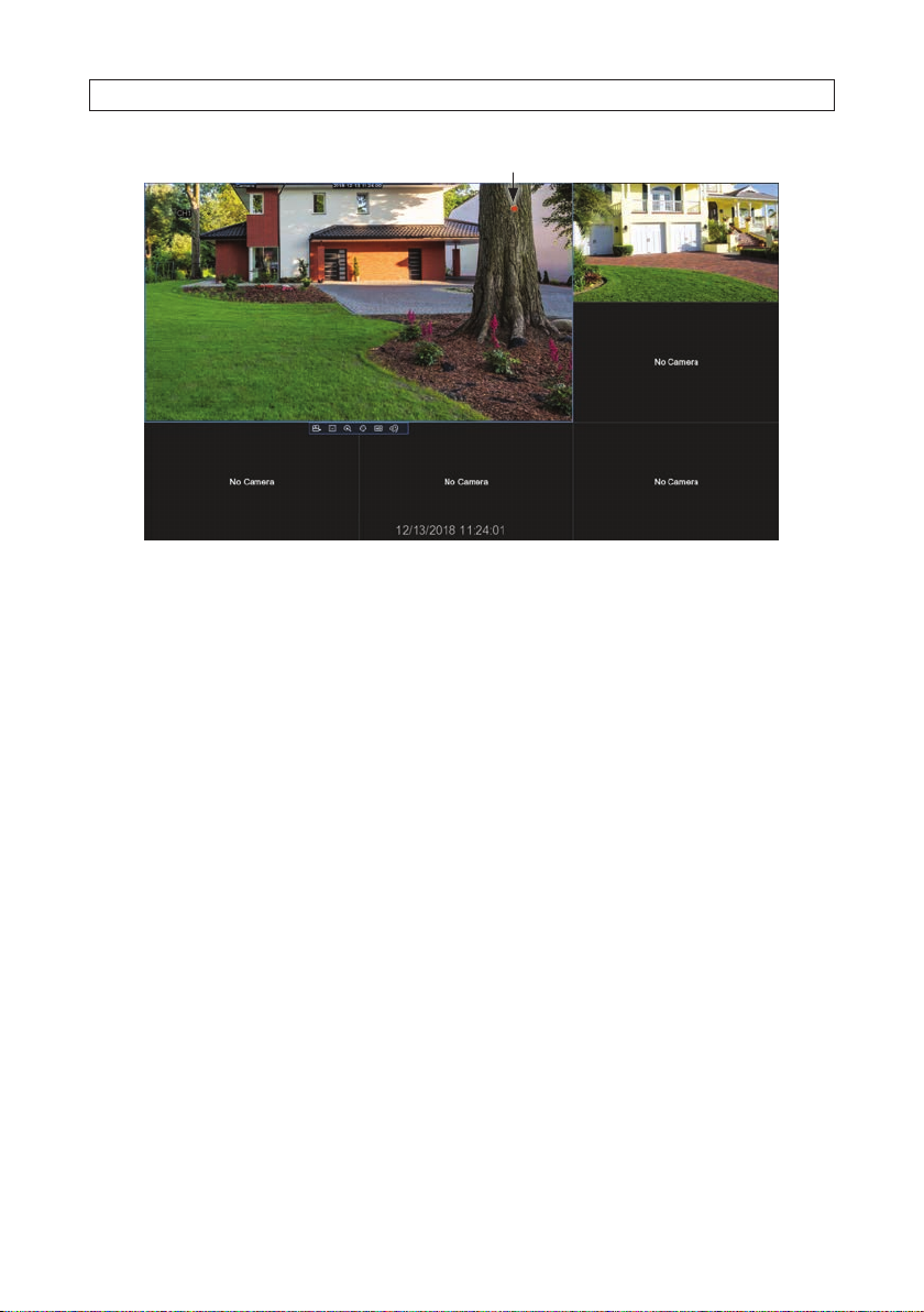
a. If cameras were added using the Wizard, video from those cameras will appear in the Live screen. See below.
Status Icons
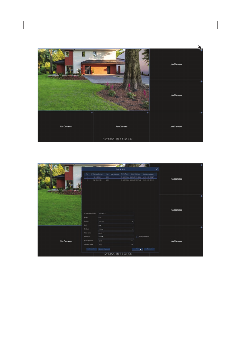
b. If you want to add cameras to the recorder, click the Add icon ( + ) in the upper right corner of the v ideo frame.
16
www.Observint.com
Page 23
SECTION 2: INITIAL SETUP
Click to add camera
i. In the Quick Add menu that opens, a list of cameras that can be added appear s at the top. Click on the one you
want to add to the viewing frame.
ii. Check the parameters in the menu to ensure they are correct (see above), and then click the Add button. Video
from the camera will appear in the viewing frame.
17N4, N8, N16, N32 NVR V8.1.0 User Manual
Page 24
SECTION 2: INITIAL SETUP
Status Icons
18
www.Observint.com
Page 25
SECTION 3: CHANNEL - LIVE DISPLAY
SECTION 3
Channel - Live Display
Use the Channel menus to congure the camera, live view display, PTZ setup, motion setup, conver t mode, and other camera related
conguration parameters. The NVR supports only compatible IP cameras connected to the backpanel.
3.1 Live display
Use the Live display to view video streaming from your cameras. The display c an show one video frame, or split into up to 16 video
frames. The display also includes Status icons in each frame that indicate is recording, or dete cted motion, and I/O alarm, or an HDD
problem.
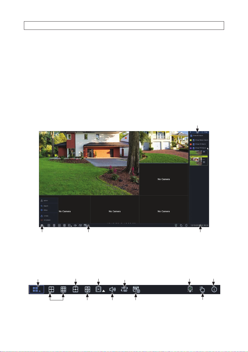
Filter panel
Task menu bar Date / TimeStart button
• Task Menu Bar
The Task Menu Bar appears at the bottom of the screen when you r ight click on the Live scren or move the mouse to the bot tom of
the screen. To open the Task Menu Bar, click the right mouse but ton anywhere in the Live View sc reen.
Open Star t menu
Screen layout
n x n
Search
playback *
View channel
sequence
Mainstream /
substream
Adjust
volume
Network
disconnected
Preview
policy**
Information
available*** Layout options
Manual Record or
Alarm start / stop
19N4, N8, N16, N32 NVR V8.1.0 User Manual
Page 26

SECTION 3: CHANNEL - LIVE DISPLAY
* Quick playback: Click to playback all channels from start of day or playback last 5 s, 10 s, 30 s, 1 min, 5 min.
** Preview policy: Realtime. Balanced, Smooth.
*** Preview policy: Click to view system, channel, or re cord information, or networ k state.
• Start Menu
To open the Start Menu, right click anywhere on the Live screen to open the Live screen toolbar, and then click the Start
Menu icon.
Click to switch user or enable multi-user.
Click for search, playback and backup (download).
Click to Setup the system (enter menu mode).
Click to Lock / Unlock the screen. Unloc k state allows access to the conguration menus.
Click to Shutdown, Reboot and Logout of the system.
— Shutdown
Click Shutdown to open the Shutdown menu. In this menu, you can either Shutdown (to power o ), Reboot, or Logout.
If you select Logout, the Live View screen will close, and you must login again to continue.
20
www.Observint.com
Page 27
SECTION 3: CHANNEL - LIVE DISPLAY
— Setup (Menu mode)
To open the Setup menus, click the icon in the lower right corner of t he Task Menu Bar, and then click the Setup icon.
Click the block for the setup con guration you want to see or change. Using these menus may require authentication.
NOTE
If the recorder is not in menu op eration for one (1) minute, the screen will lock to prevent unautho rized OSD operations.
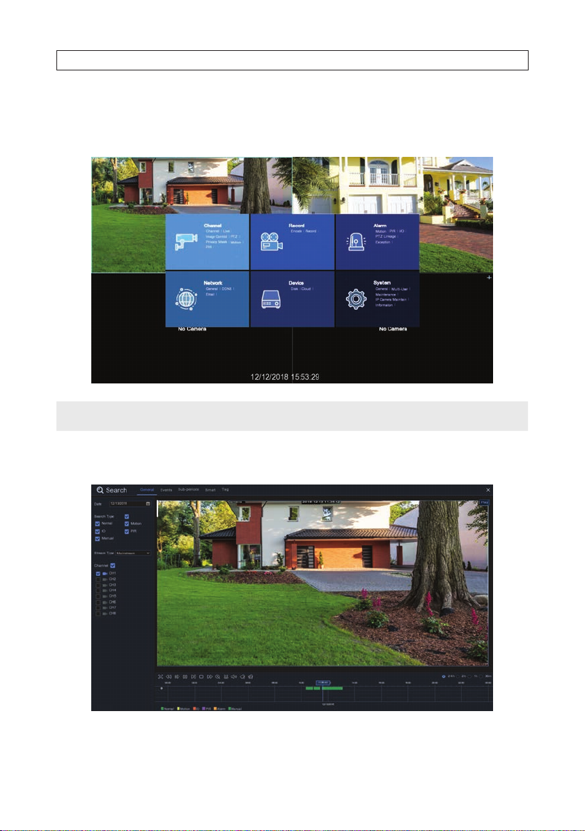
— Search
Click Search to search for recorded video.
21N4, N8, N16, N32 NVR V8.1.0 User Manual
Page 28
SECTION 3: CHANNEL - LIVE DISPLAY
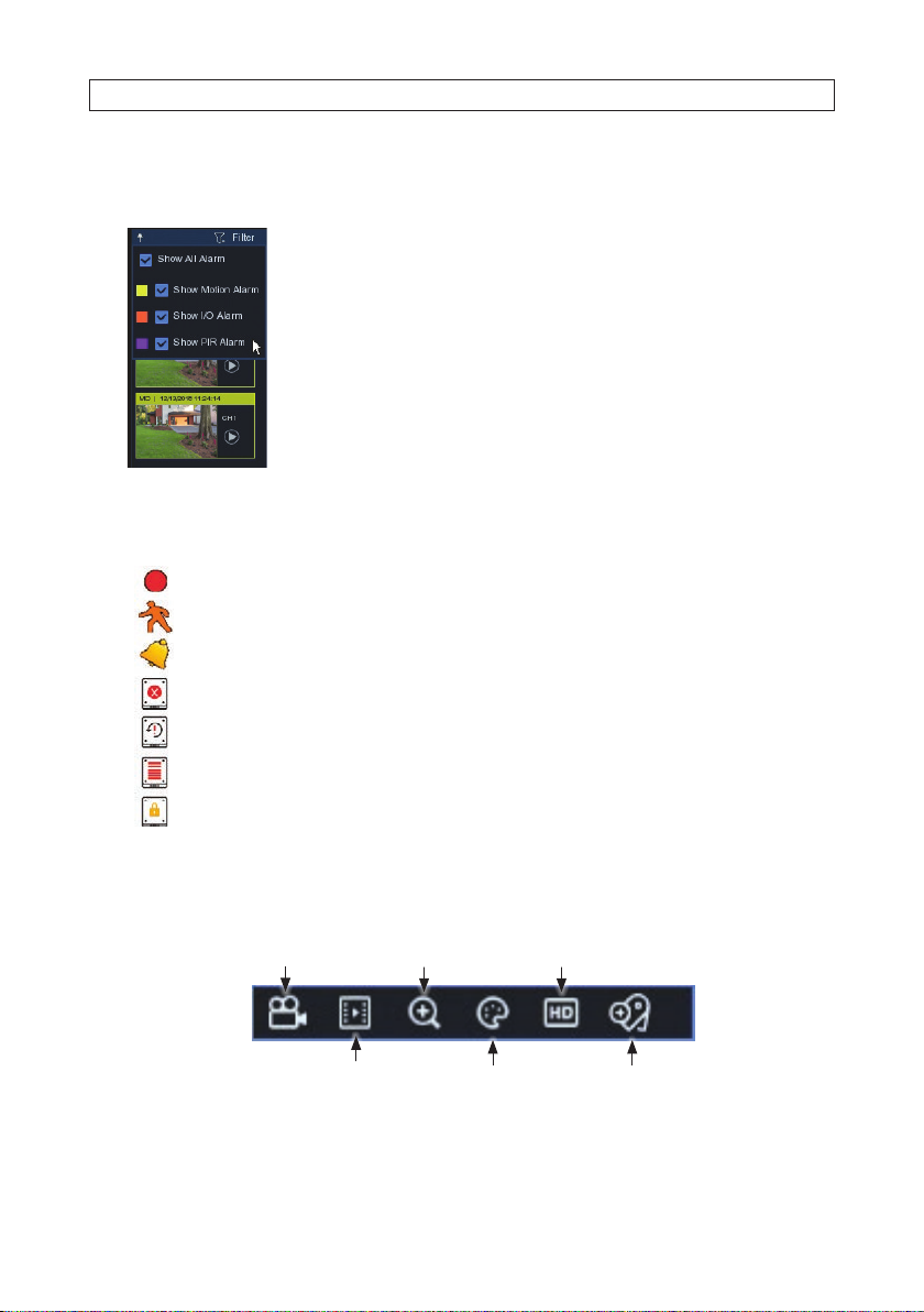
• Filter Panel
To open the Filter Panel, move the mouse cursor to the right edge of the Live screen.
The Filter panel op ens when the mouse cursor is move d to the right of the screen. It provides
links to playback re cordings, and allows you to lter recordings by the alarm type.
Click the Play icon in the thumbnail to open Search window and playback the recording.
See below.
• Status icons
Status icon can appear on the video f rame (for motion detection or recording) or on the to olbar.
This indicates that the NVR is currently recording.
This icon ap pears when the c amera has dete cted motio n.
The icon ind icates that th e external I/O a larm device is tr iggered
This icon in dicates that t he HDD is in error to w ork
This icon indicates the HDD is unformatted
This icon in dicates the HD D is full.
This icon in dicates the HD D is read-only.
• Camera Quick Setting Toolbar
The Live screen Camera Quick Se tting Toolbar will appear when you click on the video frame.
Record start/stop Zoom* Mainstream / Substream
Play last 5 min. recorded
Adjust color Add custom tag
* ZOOM: Click to zoom-in on the channel. When t he zoom icon appears, press and hold the left mouse button, then drag
across the area you want expand.
22
www.Observint.com
Page 29
SECTION 3: CHANNEL - LIVE DISPLAY
3.2 Live View screen controls
3.2.1 Channel - Live screen
To congure the Live View screen, open the Star t menu and select Setup. You may have to authenticate your credentials to open the
menu. The following S etup menu will appear over the Live View screen.
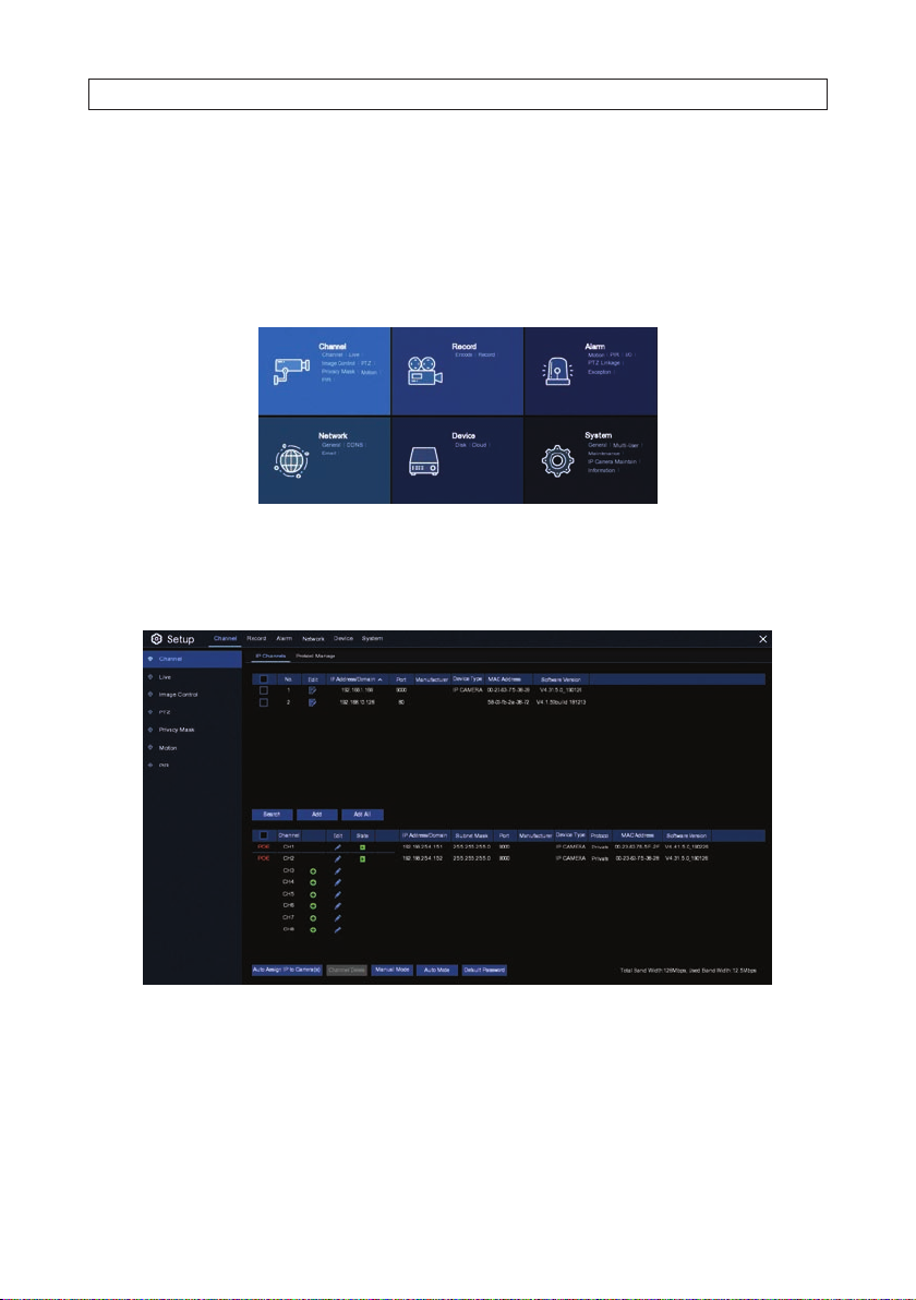
3.2.2 Channel - Channel menu
To congure the Live View screen channels, click the Channel tile. (See above.)
The Channel menu includes the following buttons:
• Search: Search for and list compatible IP cameras installed on t he network. Results of the search are shown ab ove in the
upper frame of the menu. You can modif y the settings of these camera by clicking the icon in the Edit column. See below.
23N4, N8, N16, N32 NVR V8.1.0 User Manual
Page 30
SECTION 3: CHANNEL - LIVE DISPLAY
• Add: Add a selected IP network camera to the NVR for monitoring.
• Add All: Add all compatible IP network c ameras to the NVR for monitoring.
• Auto Assign IP to Camera(s): The added IP camera would b e not able to connect if its IP address is not in the same network
segment with NVR. With this f unction to reassign an IP address to all added IP cameras.
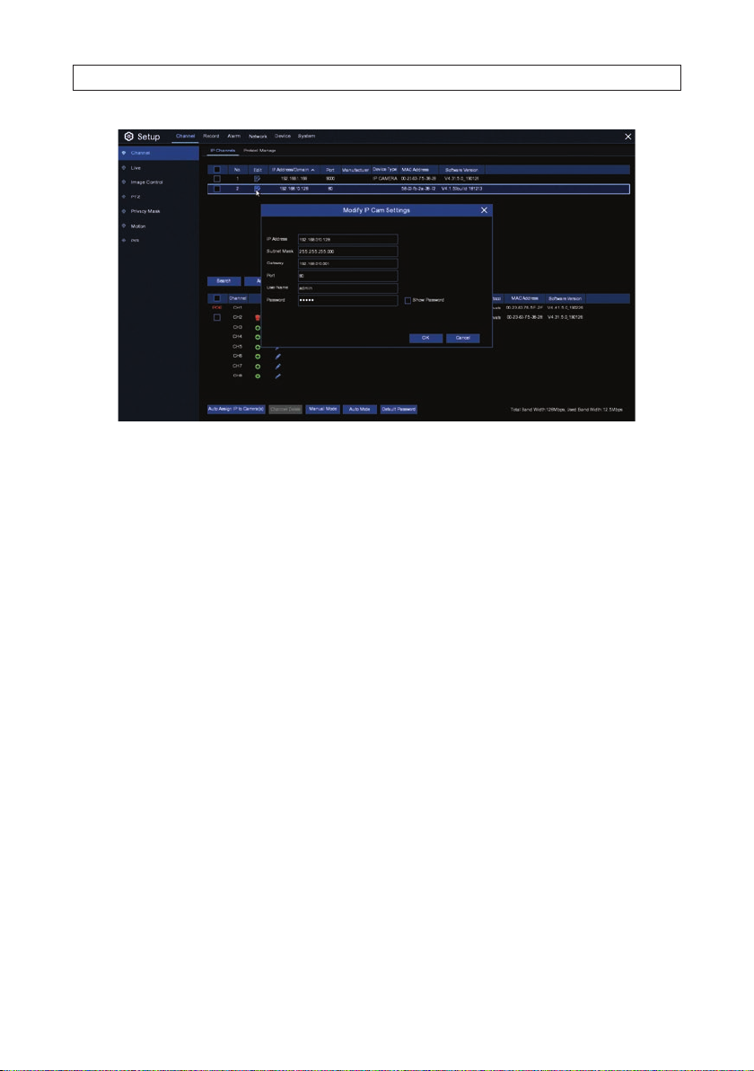
• Manual Mode: After selecting a camer a, clicking Manual Mode to open a menu for changing the net work settings of the IP
camera.
• Auto Mode: After selecting a camera, click ing Auto Mode will delete the POE chanel IP Camera.
• Channel Delete: Check the selec t box for one or more added IP cameras, and click this but ton to delete the camera.
3.2.3 Channel - Protocol Manage menu
Use the Protocol Manage menu to edit the R STP protocol for the IP camera connections. You can also use this menu to create up to
10 custom protocols. The menu is shown below.
24
www.Observint.com
Page 31

SECTION 3: CHANNEL - LIVE DISPLAY
Parameters on the Protocol Manage menu include:
• Custom Protocol: Select one of the names from the drop down list. The s ystem supports 10 cus tom protocols.
• Protocol Name: To assign a name to your custom protocol.
• Enable Substream: Check this box if you want to enable the sub-s tream.
• Typ e: Only RTSP available now.
• Port: Enter the RTSP port of your IP camera.
• Resources Path: Enter the RTSP address of your IP camera.
To use this menu:
1. Select the protocol you want to edit from the drop down list,
2. Adjust the parameters as needed
3. Click Apply.
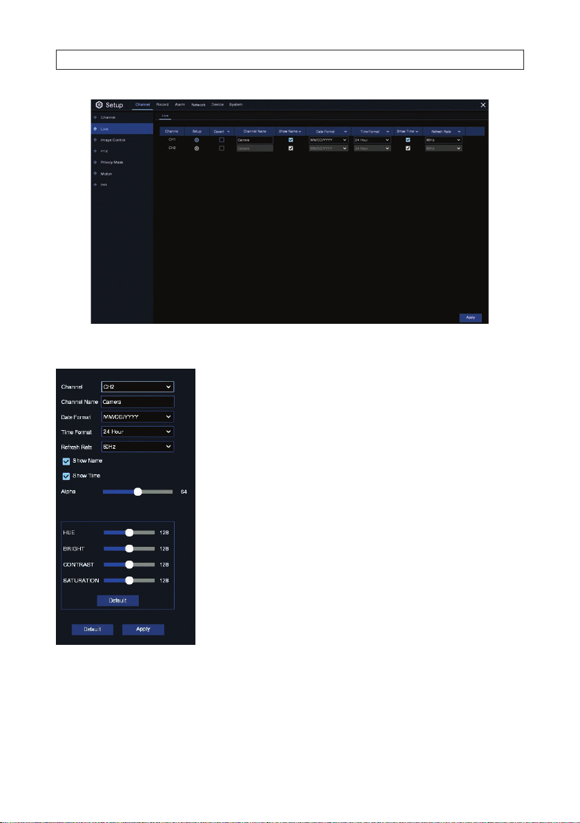
3.2.4 Channel - Live menu
In the Live menu, click the Setup icon for each camera to congure the on-s creen display (OSD) options and adjust the color and
brightness p arameters.
25N4, N8, N16, N32 NVR V8.1.0 User Manual
Page 32
SECTION 3: CHANNEL - LIVE DISPLAY
Setup menu:
Choose a channel to congure Give a name to the c amera
Date format to display for the camera (for IP c amera only)
Time format to display for the camera (for IP camera only) Ref resh Rate of the camera
(for IP camera only)
Show Name, Show Time - show on sc reen options
Alpha - use to set the t ransparency of the OSD camera name, date and time, etc.
Adjust the Hue, Brightness, Contr ast and Saturation values for the image
Click Default to load default set tings.
Right click on the Setup menu to return, click Apply to save your settings, and then right click on the menu to exit.
26
www.Observint.com
Page 33
SECTION 3: CHANNEL - LIVE DISPLAY
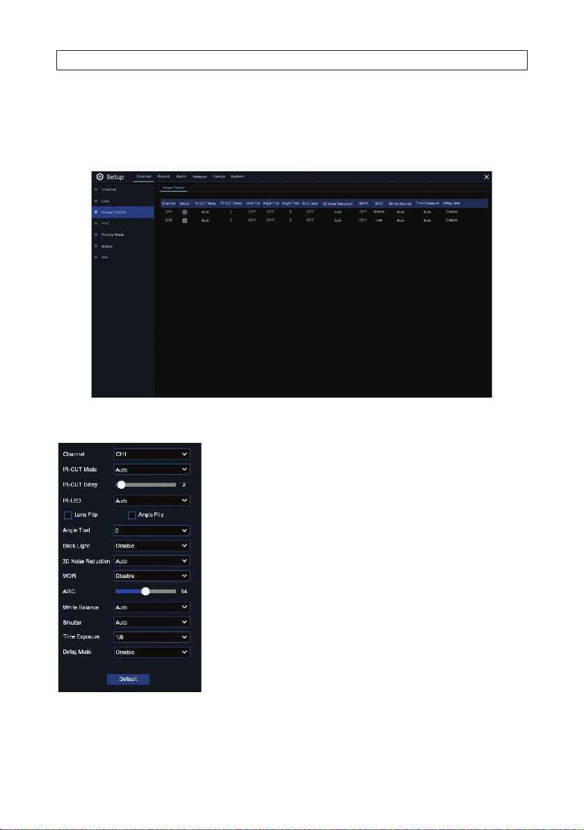
3.2.5 Channel - Image Control menu
Use the Image Control menu to congure additional parameter s for the camera. Click on the icon in Setup column for each camera
to congure additional performance settings.
Setup menu includes:
Choose a c hannel to congu re
Selec t the desired bu ilt-in IR cut lte r mode to ensure th e camera work s properly bo th in the day and nigh t.
Set the de lay time of IR-CU T switching Che ck to enable lens ip and angle ip Set t he ip angle
To enable or disable Backlight compensation
Choose t he appropria te options to rot ate / ip the image. F or Angle Flip, select teh Angle Trad 0 or 360.
Select Enable to choose Backlight compensation.
Selec t Enable to choo se 3D Noised Red uction.
Selec t Enable to use WDR
Use the slid er to adjust Auto matic Gain Cont rol level
Selec t White Balance Au to to enable the cam era to automati cally adjust t he brightnes s and contrast o f the
video wh en shooting in th e darkness wi th bright light s ources.
Set the Shu tter and Time E xposure as n eeded.
Use in fog gy environment s to improve the vi deo quality
Click Def ault to retur n to Image Control d efault set tings.
Right click on the Setup menu to return, click Apply to save your settings, and then right click on the menu to exit.
27N4, N8, N16, N32 NVR V8.1.0 User Manual
Page 34

SECTION 3: CHANNEL - LIVE DISPLAY
3.2.6 Channel - PTZ menu
Use the PTZ screen to congure camer as with PTZ (Pan and Tilt and/or Zoom) capability. In the screen shown below, the only
camera listed has variable zoom.
To use this menu, open the Signal Type drop down list for the camera you want to congure. If you selec t Digital control, you can
control the PTZ f eatures through menus in the NVR. If you select Analog control, you must se t the analog parameters so they are
consistent with the sett ings in the camera.
Columns on the PTZ menu include:
• Signal Type: Analog for analog channels, Analog & Digital for IP channels.
• Protocol: Choose t he communication protocol between the PTZ capable camera and NVR. The NVR supports Pelco -D and
P el co - P.
• Baudrate: The speed of the infor mation sent from the NVR to the PTZ camera. Make sure it matches the compatibility level of
your PTZ camera.
• DataBit / StopBit: The information betwe en the NVR and PTZ camera is sent in individual package s. The DataBit indicates
the number of bit s sent, while the EndBit indicates the end of the package and the beginning of the nex t (information)
package. The available parameters f or DataBit are: 8, 7, 6, 5. Options for the StopBit are 1 or 2.
• Parity: For error check. See the do cumentation of your PTZ camera, to congure this set ting.
• Address: Set the command address of the PTZ sys tem. Please be noted that each PTZ camer a needs a unique address to
function properly.
3.2.7 PTZ control panel
To open the PTZ control panel, click on the camera video in the Live display, and then click the PTZ cont rol panel icon on the
Camera Quick Setting toolbar. A menu will open on the sidebar. Using this menu you can adjust the Zoom and F ocus.
28
www.Observint.com
Page 35
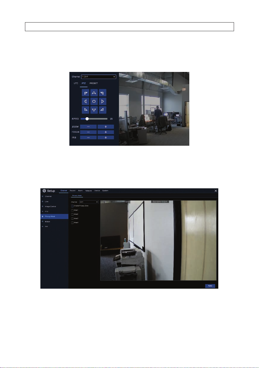
SECTION 3: CHANNEL - LIVE DISPLAY
PTZ
Use the PTZ menu to point the camera at your surveillance target and control the ZOOM, and FOCUS. The SPEED slider controls how
fast the camera moves.
3.2.8 Channel - Privacy Mask menu
Use the Privac y Mask menu to block areas of the eld of view where information may appear that you do not want to view or record.
You can congure up to four privacy areas in the eld of view.
To use this feature:
1. Check the Enable Privacy Zone select box.
2. Check the select box for one of the four privacy areas you can congure. In the e xample below, Area 1 was selected.
29N4, N8, N16, N32 NVR V8.1.0 User Manual
Page 36
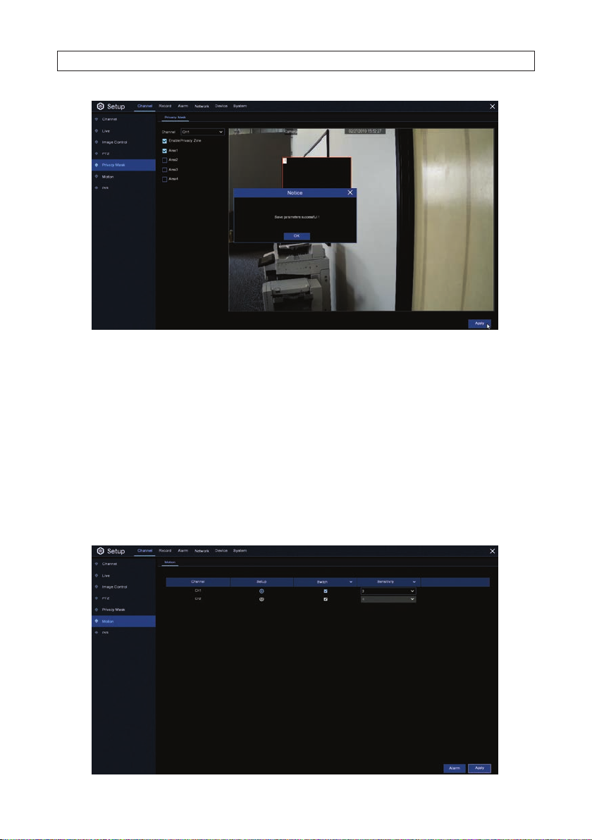
SECTION 3: CHANNEL - LIVE DISPLAY
3. Using the mouse, drag a rec tangle across the area you want to hide. In the example above, the whiteboard is obscured.
4. Click Apply to save your set tings.
5. Congure another privac y area if needed. Check the s elect box for an unused area, and then repeat steps 3 through 4 above.
You can remove a privacy area by unchecking the select box for that area, and then clicking Apply.
3.2.9 Channel - Motion menu
Use the Motion menu to congure areas in the camera eld of view where motion of interes t can occur. When motion is sensed
in those areas, your NVR can record the event and notify you by sending an email aler t with an attached image of the event, and/
or send a push notications to your HDVision Mobile app. Motion event recording is enabled with a Sche dule. See “4.2.1 Record
Schedule” on page 37 for more information.
30
www.Observint.com
Page 37

SECTION 3: CHANNEL - LIVE DISPLAY
By default, t he entire eld of view is selected for Motion detection, as indicated by the orange tinted segments over the bac kground.
To congure a camera for motion detect ion:
1. Check the Swi tch select box to enable Motion Detection for that camera.
2. Open the Sensitivit y drop down list to select the s ensitivity of detec tion. Level 1 provides the lowest s ensitivity, and level 8
provides the highest sensit ivity. Selecting the sensitivity correct ly may require testing.
3. Click the icon in the Setup column. In the scre en that opens, you can select the areas of the camera eld of view were you
want to sense for motion. By default, the entire eld of v iew is selected, indicated by t he orange tint. For improved eciency of
your system, click Clear All areas, and then drag a rec tangle across only the areas where motion is of interest.
Motion detection area (orange highlight)
— To disable motion detection in an area of the screen where it is being sensed, drag a rec tangle with the mouse across the
area, start ing on a segment highlighted in orange, where motion detec tion is enabled.
— To enable motion detection in an area of the screen where it is not being sensed, drag a rec tangle with the mouse across
the area, star ting on a segment that is not highlighted, where motion detection is dis abled.
4. Right click on the Setup screen to ret urn to the Motion menu, and then click Apply to save your set tings.
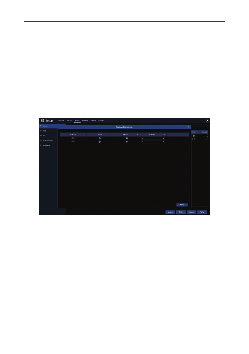
5. Click the Alarm button to open the Motion Alar m menu. Use this menu to congure how the recorder will react to a motion
detection event. The Motion Alarm menu is shown below.
31N4, N8, N16, N32 NVR V8.1.0 User Manual
Page 38

SECTION 3: CHANNEL - LIVE DISPLAY
6. Congure the motion alarms for the camera you are conguring, change the f ollowing parameters as neede d:
— Buzzer: The NVR can use its internal buz zer to emit an alarm tone. You can set the buzzer duration in seconds when the
motion is detected.
— Alarm Out: Optional function. If your NVR support to connec t to external alarm device, you can set to emit an alarm
tone.
— Latch Time: To congure the ex ternal alarm time when motion is detected.
— Record: Click the settings icon and choose which channel(s) you want to record when the motion detection is t riggered.
— Post Recording: You can set how long af ter an event occurs that the NVR will continue to record. The recommended
recording length is 30 seconds but i t can be set higher up to 5 minutes.
— Show Message: Check the select box to display the motion icon on the live view screen when the motion is detec ted.
— Send Email: You can let the NVR to send you an auto-email when the motion is detected. You must congure your
email settings to use this feature. See “6.3 Email setup” on page 48.
— Full Screen: If this func tion is enabled and a motion is detec ted in a channel, you will see that channel in f ull screen.
— Picture to Cloud: Select this option to upload a picture (capture) of the event to your cloud server. The Cloud ser ver
must be congure d. See “7.2 Cloud settings” on page 53.
— Video to Cloud: Select this option to upload video of the event re corded on the HDD to your cloud ser ver. The Cloud
server mus t be congured. See “7.2 Cloud settings” on page 53.
7. Click Save to retain your set tings. You can also click Copy to use the alarm settings with other cameras.
8. Right click the mouse to retur n to the Motion menu.
3.2.10 PIR
Use the PIR menus to dene a detection areas for cameras that senses for a heat signature (PIR). Only PIR capable cameras can be
congured for PIR detection. To improve the eciency of your system, sense for PIR only in areas of the eld of view where PIR
sensing is valuable.
32
www.Observint.com
Page 39

SECTION 3: CHANNEL - LIVE DISPLAY
To setup cameras to use t he PIR feature:
1. Check the Swi tch box for a PIR capable camera to enable PIR detec tion.
2. Set the sensitivit y level for the area you setup for PIR detection. Level 1 the lowest sensitivit y level, level 8 is the highest
sensitivity level.
3. Click the icon in the Setup column to open the setup menu. See b elow.
By default, t he entire eld of view is selected for PIR sensing, as indicated by the orange tinted segments over the bac kground.
To select only the se gments where a heat signature detection is valuable:
a. Click Clear All to clear all selected segments in the eld of view.
33N4, N8, N16, N32 NVR V8.1.0 User Manual
Page 40
SECTION 3: CHANNEL - LIVE DISPLAY
b. Select areas for PIR sensing as follows:
* To enable PIR sensing in an area of the screen where it is not being sensed, drag a rectangle with the mouse across
the area, star ting on a segment that is not highlighted, where PIR sensing is disabled.
* To disable PIR sensing in an area of the screen where it is being sensed, drag a re ctangle with the mouse ac ross the
area, start ing on a segment highlighted in orange, where PIR sensing is enabled.
c. Right click on the Setup screen to retur n to the PIR menu, and then click Apply to retain your settings.
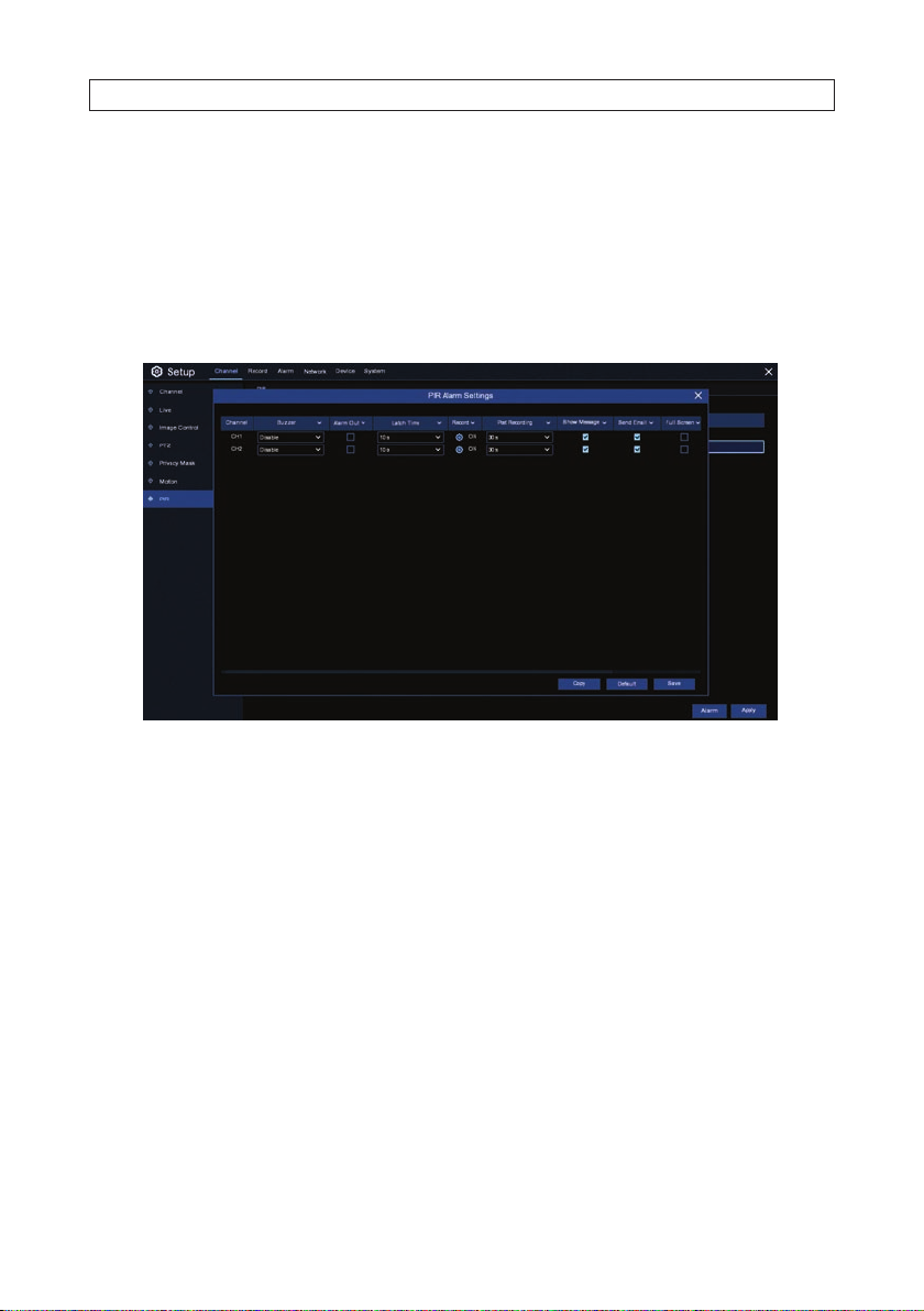
4. Click the Alarm button at the bottom of the s creen to open the PIR Alarm menu.
PIR ALARM settings
5. Congure the PIR alarms for the camera you are conguring, change the following parameters as neede d:
— Buzzer: Enable this option to sound an alarm tone when a PIR event is detec ted. You can set the buzzer duration in
seconds when the PIR is detected.
— Record: Click the settings icon and choose which channel(s) you want to record when the motion detection is t riggered.
— Post Recording: You can set how long af ter an event occurs that the NVR will continue to record. The recommended
recording length is 30 seconds but i t can be set higher up to 5 minutes.
— Show Message: Check the select box to display the motion icon on the live view screen when a PIR event is de tected.
— Send Email: You can let the NVR to send you an auto-email when a PIR event is detec ted. You must congure your email
settings to use this feature. See “6.3 Email setup” on page 48.
— Full Screen: Check the sele ct box to expand the live view display of the channel to ex pand to full screen when a PIR
event is detec ted.
— Picture, Video to Cloud Uploads: Check the select box(es) to upload image s and/or videos to the Cloud service when
a PIR event is detec ted. To enable the cloud s ervice, please see “7.2 Cloud settings ” on page 53.
6. Click Save to retain your set tings. You can also click Copy to use your alarm settings with other PIR capable c ameras.
7. Right click the mouse to retur n to the PIR menu.
34
www.Observint.com
Page 41

SECTION 4: RECORD
SECTION 4
Record
Uses the Record menus to congure the re corder for encode the video and capture les, and when it will record.
4.1 Encode
Use the Encode Mainstream and Substream menus to congure t he recording resolution, compres sion, etc. for each camera channel,
and to enable Audio on the channel if available. In general, Mainstream congure s the channel for the highest video resolution from
the camera, and substream set s the video quality used for remote access (web client, smar tphone app) and a central management
soft ware (CMS).
To open the Encode menus, click the Record tile in the main menu or click the Record tab on the Setup screen, and then click the
Encode link the lef t panel.
Mainstream setup
1. In the Encode menu, click the Mainstream tab.
2. Congure each camera channel for t he recording parameters you want to us e. Recording parameters include:
— Resolution: Resolution parameter denes how large the recorded image w ill be. Of ten this parameter is set to the
maximum resolution of the camer a connected to the channel.
— FPS: This parameter dene s the number of frames per second the NVR will record. This parameter has a large eect on
the amount of video data recorded on the HDD.
— Video Encode Type: This NVR supports both H.265 and H.264 encoding.
35N4, N8, N16, N32 NVR V8.1.0 User Manual
Page 42

SECTION 4: RECORD
— Bitrate Control: Select the bitrate level. For a simple scene, such as a gray wall is suitable constant bitrate (CBR). For
more complex scene, such as a busy street is suitable variable bitrate (VBR).
— Bitrate Mode: If you want to set the bitrate, then cho ose User-dened mode. If you want to selec t the predened
bitrate, choose Predened mode.
— Bitrate: This parameter indicates the rate of data transf er that the NVR, and the data rate of vide o recording. Recordings
encoded at higher bitrates will generally have a higher quality.
— Audio: Select this option if you want to record audio with video. You must have a microphone connected to the NVR or
are using a camera wi th audio capability. Audio channels are asso ciated with the camera channels as shown in the menu.
— I Frame Interval: In compressed video format, the number of frames that only show changed pixels bet ween a full
frame of the current video image The lower the iframe interval, the higher the video quality, with a higher network
bandwidth. Video containing a high level of motion (city street trac, etc) should have a low iframe interval for better
video quality.
— ETR: ETR is used to sele ct the same resolution, f rame rate, etc settings for PIR/Motion tr iggered recording as other
recording mode s. If ETR is not selected, PIR /Motion triggered recordings can have dierent resolution and f rame rate
settings from other recording modes..
3. After changing parameters in the menu, clic k Apply to save your settings.
Substream setup
1. Click the Substream tab to open the sub stream menu.
2. Congure each camera channel for t he substream recording parameters you want to use. You can use the Copy feature
to apply the set tings of one camera channel to other channels. Parameter denitions are similar to the Mainstream setup
parameters. Use the denitions shown above.
3. Click Apply to save your set tings.
4.2 Record
In the Record menu, use the Record tab to enable recording, sele ct the stream (Mainstream or Dualstream) you want to record, and
enable PreRecord if needed. The Record menu Record tab is shown below.
36
www.Observint.com
Page 43

SECTION 4: RECORD
1. In the menu shown above, select the options you prefer for each camera channel:
— Record Switch: Check the sele ct box to enable recording this channel.
— Stream Mode: Choose video streams you want to record. You can record either Mainstream (only) or Dualstream
(Mainstream and Subs tream). If Audio is enabled on the channel, audio will also be recorded.
— PreRecord: When this option is enabled, the NVR will b egin recording a few seconds be fore an alarm event occurs. Use
this option if recording is triggered by motion.
2. Click Apply to save your settings. You can also click Copy to copy your settings to other channels.
4.2.1 Record Schedule
Use the Record Schedule graphical user interf ace (GUI) to dene when recording a channel is enable for either Normal (continuous)
recording, Motion t riggered recording, or PIR triggered recording during the week. Notice that the schedule three rows for each day
(one to mark Normal recording, one for Motion recording, and one for PIR recording), and one column for each 30 minute period.
For each 30 minute segment of each day of the week, you can disable recording (no recording mo de selected), or enable either the
Normal, Motion, IO, or PIR recording mode.
The Recording Schedule GUI is shown below. Note that each dierent recording mode is color-co ded on the schedule. Shown here,
the schedule is congured for only f or Motion recording, Sunday through Friday.
37N4, N8, N16, N32 NVR V8.1.0 User Manual
Page 44

SECTION 4: RECORD
To congure a recording schedule for a camera channel:
1. Open the Channel drop down lis t at the top of the menu and select the camera channel you want to congure.
2. Click on one of the recording mode s listed to the right of the matrix (Normal, Motion, IO or PIR).
3. Drag the mouse linearly or diagonally across an area of the matrix where you want to enable that recording mode. To disable a
recording mode on the schedule, select the mo de you enabled, and then drag the mouse across the area you want to disable.
4. Select a dierent mo de, and repeat the method in step 3 above.
5. When nished setting up the sche dule, click Apply to activate it. You can also click Copy to use the same schedule for other
camera channels.
38
www.Observint.com
Page 45
SECTION 5: ALARM CONFIGURATION
SECTION 5
Alarm Conguration
Use the Alarm menus to congure alarm parameters. MOTION and PIR menus included here are similar to the alarm menus in
related sec tions of the manual.
5.1 Motion alarm handling
To open the Motion alarm menu, click the Alarm tile in then Main menu, and then click the Motion link in the lef t column. Use this
menu to congure how the re corder will react to a motion detec tion event. The Motion Alarm menu is shown below.
1. Congure the motion alarm options for t he camera you are conguring:
— Buzzer: The NVR can use its internal buz zer to emit an alarm tone. You can set the buzzer duration in seconds when the
motion is detected.
— Alarm Out: Not used.
— Latch Time: Use the Latch Time parameter to set how long the buz zer will sound when the alarm is triggered (10s, 20s,
40s, and 60 s).
— Record: Click the settings icon and choose which channel(s) you want to record when the motion detection is t riggered.
— Post Recording: You can set how long af ter an event occurs that the NVR will continue to record. The recommended
recording length is 30 seconds but i t can be set higher up to 5 minutes.
— Show Message: Check the select box to display the motion icon on the live view screen when the motion is detec ted.
— Send Email: You can let the NVR to send you an auto-email when the motion is detected. You must congure your
email settings to use this feature. See “6.3 Email setup” on page 48.
— Full Screen: If this func tion is enabled and a motion is detec ted in a channel, you will see that channel in f ull screen.
39N4, N8, N16, N32 NVR V8.1.0 User Manual
Page 46
SECTION 5: ALARM CONFIGURATION
— Picture, Video to Cloud: Check the select box(es) upload alarm images and/or videos to a Cloud server when a PIR
event is detec ted. To enable the Cloud server, please see “7.2 Cloud settings” on page 53.
2. Click Apply to save your settings. You can also click Copy to use the same set tings for other camera channels . Right click the
mouse to retur n to the Live View Main menu.
3. Click the Motion button to (re)congure the motion dete ction settings fo r a camera. Options in this menu are the same as
those in the Channel | Motion menu. See “3.2.9 Channel - Motion menu” on page 30 for more information.
5.2 PIR
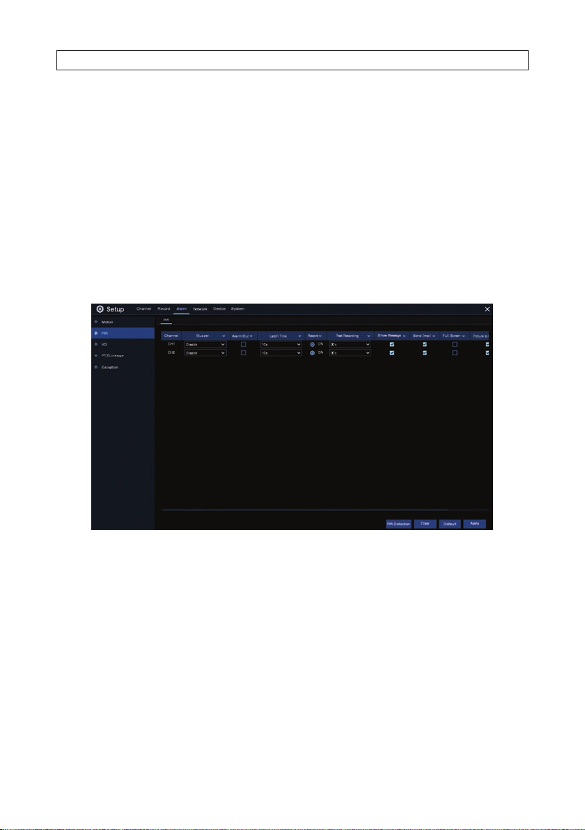
To open the PIR alarm menu, click the Alarm tile in then Main menu, and then click the PIR link in the left column. Use this menu to
congure how the recorder will react to a PIR detection event. The PIR alarm menu is shown below.
1. Congure the PIR alarm options for the camera you are conguring:
— Buzzer: Enable this option to sound an alarm tone when a PIR event is detec ted. You can set the buzzer duration in
seconds when the PIR is detected.
— Alarm Out: Not used.
— Latch Time: Use the Latch Time parameter to set how long the buz zer will sound when the alarm is triggered (10s, 20s,
40s, and 60 s).
— Record: Click the settings icon and choose which channel(s) you want to record when the PIR event is sens ed.
— Post Recording: You can set how long af ter an event occurs that the NVR will continue to record. The recommended
recording length is 30 seconds but i t can be set higher up to 5 minutes.
— Show Message: Check the select box to display the motion icon on the live view screen when a PIR event is de tected.
— Send Email: You can let the NVR to send you an auto-email when a PIR event is detec ted. You must congure your email
settings to use this feature. See “6.3 Email setup” on page 48.
40
www.Observint.com
Page 47
SECTION 5: ALARM CONFIGURATION
— Full Screen: Check the sele ct box to expand the live view display of the channel to ex pand to full screen when a PIR
event is detec ted.
— Picture, Video to Cloud: Check the select box(es) to upload images and/or videos to the Cloud service when a PIR
event is detec ted. To enable the cloud service, please s ee “7.2 Cloud settings” on page 53 .
2. Click Apply to retain your set tings. You can also click the Copy button to copy your sett ings to dierent camera channels.
Right click the mouse to return to the Live View Main menu.
3. Click the PIR Detection button to (re)congure the PIR detect ion settings for a camera. Options in this menu are the same as
those in the Channel | PIR menu. See “3.2.10 PIR” on page 32.
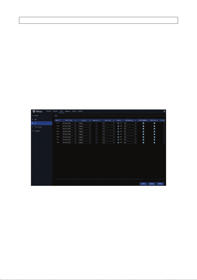
5.3 IO alarm menu
This menu is reser ved for future enhancement. It does not apply to NVRs withou t alarm input sensing.
5.4 PTZ Linkage alarm menu
To open the PTZ Linkage alarm menu, click the Alarm tile in t hen Main menu, and then click the PTZ Linkage link in the left
column. For PTZ cameras only, you can point the camera to a Preset when a Motion or PIR alarm event occurs. The Preset must b e
precongured. T he PTZ Linkage menu is shown below.
41N4, N8, N16, N32 NVR V8.1.0 User Manual
Page 48

SECTION 5: ALARM CONFIGURATION
1. Congure the PTZ Linkage alarm options for the camera you are conguring:
— Switch: Check the select box to enable the PTZ linkage feature.
— Motion: Check the select box to enable a Motion detection alarm event to point a PTZ camera at a Preset eld of view.
— IO: This feature not currently used.
— PIR: Check the selec t box to enable PIR alarm event to point a PTZ camera at a Preset eld of view.
— PTZ1 .. 4: Click the Settings icon assoc iated with a PTZ camera, and then, in the popup menu, selec t the PTZ camera
channel and a Prese t eld of view associated with the camera to point the camera in that dire ction when Motion and/or
PIR alarm event occurs.
2. Click Apply to retain your set tings. You can also click the Copy button to copy your sett ings to dierent camera channels.
Right click the mouse to return to the Live View Main menu.
42
www.Observint.com
Page 49

SECTION 5: ALARM CONFIGURATION
5.5 Exception
To open the Exception event menu, click the Alarm tile in then Main menu, and then click the Exception link in the left column.
The Alarm Exception menu is shown below.
Use the Exception menu to congure the re corder to send alert(s) when certain conditions occur. At this time, the event types
include:
— No Space on Disk: When an HDD is full.
— Disk Error: If the HDD is not detecte d properly.
— Video Loss: If a camera is not connected properly or a failure in the network or camera occurs.
1. For each Exception type, congure the following:
— Switch: Check the select box to enable the monitor ing of the event.
— Buzzer: Set the buz zer duration when the event occurs (O/10s/20s/40s/60s). To disable buzzer, select OFF.
— Alarm Out: Check the select box to enable the ex ternal alarm device to sound. Recorder must be connected to an
external Alarm Out device, such as a buzzer. This feature is not currently implemented.
— Latch Time: Specify how long an ex ternal alarm device will sound (10s, 20s, 40s, 60s). Recorder must be connected to
an external Alarm Out device, such as a buzzer.
— Show Message: Check the select box to display a message on the screen when the Exception event occurs.
— Send Email: Check the select box to s end you an auto-email when the Exception event occur s.
2. Click Apply to retain your set tings. Right click the mouse to return to the Live View Main menu.
43N4, N8, N16, N32 NVR V8.1.0 User Manual
Page 50

SECTION 6: NETWORK CONFIGURATION
SECTION 6
Network Conguration
Use the Network conguration menus to setup This menu allows you to congure network parameters, such as PPPoE, DHCP, and
3G. The most common types are DHCP. Most probably your network type is DHCP, unless the network is manually addressed. If you
need an authent ication user name and password to t he Internet, then choose PPPoE. If you want to use mobile network connection,
then choose 3G.
6.1 General settings
Open the Net work General settings menu by clicking the Network tab in the Live View Main menu. Network general set tings show
the Ethernet (L AN) settings for the recorder, and the network settings for the internal s witch (Internal NIC) where IP cameras are
connected to the backpanel. In this menu, you can use D CHP to acquire compatible Ethernet net work settings from a DHCP server
on your network (often with a router), or disable DHCP (uncheck the DHCP box) and enter your ow n settings. Settings you use must
be compatible with other devices on the network to avoid network IP address conicts.
Parameters shown in the General screen include:
LAN
— IP Address: The IP address is the unique identier f or every machine using network. It consis ts of four groups of
numbers bet ween 0 to 255, separated by periods. F or example, “192.168.001.100”. Each device on a net work must have a
unique network IP address and b e compliant with network addre ssing rules.
— Subnet Mask: Subnet mask is a network p arameter which denes a range of IP addresses that can be used in a
network . If IP address is like a street where you live then subnet mask is like a neighborhood. The subnet address also
consists of four groups of number s, separated by periods. For example, “255.255.000.00 0”.
44
www.Observint.com
Page 51

SECTION 6: NETWORK CONFIGURATION
— Gateway: This address allows the NVR to access the Internet. The format of the Gate way address is the same as the IP
Addr ess. For exampl e, “192.168.001.0 01”.
— DNS1/DNS2: DNS1 is the primar y DNS (Domain Name Server) server and DNS2 is a backup DNS ser ver. A DNS server
translates a website host name (such as E SPN.com) to the IP address understood by routers on the internet. The de fault
DNS addresses are 8.8.8.8 and 8.8.4.4 (provided by Google).
Internal NIC
— IP Address: This IP address represents the gateway IP address of the internal switch of the NVR to which IP cameras are
connected. Each IP camera connected to the internal switch has a dierent IP address.
— Subnet Mask: Subnet mask is a network p arameter which denes a range of IP addresses that can be used in the
internal switch. Typically this parameter is 2 55.255.255.000 and rarely needs to change.
6.1.1 PPPoE settings
PPPoE (Point-to-Point Protocol over Ethernet) is a spe cication for connecting multiple users on an Ethernet local area net work to a
remote site through common customer premises equipment, such as a DSL modem.
PPPoE is disabled by de fault. To use PPPoE:
1. Check the PPPoE select box, and then enter the User name and Password of the PPPoE device.
2. Click Apply to save your settings.
3. Reboot the recorder to ac tivate the PPPoE settings.
45N4, N8, N16, N32 NVR V8.1.0 User Manual
Page 52
SECTION 6: NETWORK CONFIGURATION
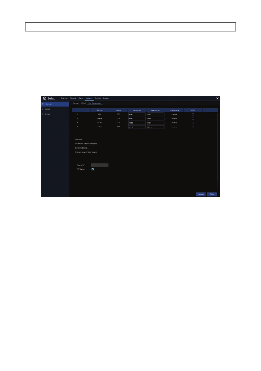
6.1.2 Port Conguration
The Port conguration menu is used to adjust the Ethernet por ts used to address the Web, Media, R STP and HTTPS service s.
Normally these ports numbers do not ne ed to change unless the ports are also used by other devices.
The port f eature supports UPnP (Univer sal Plug and Play) a useful feature for automatically por t forwarding a router for direct access
to the recorder f rom Internet. The Port congur ation menu is shown below.
Port conguration parameters include the following.
— Web Port: This por t is used to log in remotely to the recorder (e.g. using the Web Client). If the default port 80 is already
taken by other applicat ions, please change it.
— Client Port: This is the port the recorder will use to send information. If the default port 90 00 is already taken by other
applications, please change it.
— RTSP Port: Default is 1050, if the default port 1050 is already taken by other applicat ions, please change it.
— UPNP: If you want to log in to the recorder remotely using a Web Client, you need to por t forward the router for your
recorder. If your router supports UPnP, you can enable it both in the router and re corder to automatically setup por t
forwarding for a remote login. O therwise, it must be setup manually.
Adjust the por t conguration parameters as needed, and then click Apply. Right click the mouse to return to the Main menu.
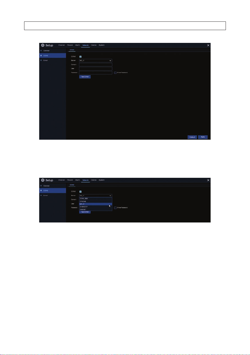
6.2 DDNS settings
This menu allows you to congure DDNS settings. The DDNS prov ides a static address to simplif y remote connection to your
remotely. To use the DDNS, you rst ne ed to open an account on the DDNS service provider’s web page.
Observint technologie s recommends a P2P DDNS service. Options include No-IP, DYNDNS, DDNS_3322, CHANGEIP, and DNSEXIT.
46
www.Observint.com
Page 53
SECTION 6: NETWORK CONFIGURATION
1. To use DDNS with your recorder, select the preferred options in the screen shown above:
— DDNS: Check the select box to enable DDNS.
— Server: Open the Server drop down list to select the pre ferred DDNS server (DDNS_3322, DYNDNS, NO_IP, CHANGEIP, or
DNSEXIT).
— Domain: Enter the domain name you created on the DDNS service provider’s web page. This will be the address you
enter in the URL box when you want to connect remotely to the recorder via PC. Fox example: NVR.no-ip.org.
— User/Password: Enter the user name and password you obtained when creating an account on the DDNS s ervice
provider’s web page.
2. After all parameters are entered, click Test DDNS to test the DDNS set tings. If the test result is “N etwork is unreachable or DNS
is incorrect”, please verify that the network is f unctioning properly, and the DDNS information is cor rect or not.
3. Click Apply to save your set tings. Right click the mouse to return to the Main menu.
47N4, N8, N16, N32 NVR V8.1.0 User Manual
Page 54
SECTION 6: NETWORK CONFIGURATION
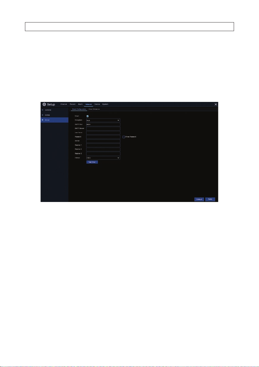
6.3 Email setup
To use Email notications of an alarm event, use the Email setup menu to congure your account settings. You can receive an Email
notication when an alarm is triggered, the HDD be comes full, the HDD is in error state, or a Video Loss occur s. You can congure
the menu to send Email notications to up to three recipients. Notic ation email will appear in your account Sent fo lder.
Use the Email Schedule menu to specify when email notications are sent. This sc hedule must be congured to complete email
setup.
1. To setup your recorder fo r Email notications, congure the following parameters:
— Email: Check the select box to enable your Email set tings.
— Encryption: Open the drop down lis t and select the appropriate option for your Email provider. Options include Auto,
SSL, TSL, and Disable. If you are unsure about the cor rect setting, set Encrypt ion to Auto (defaul t).
— SMTP Port: Enter the SMTP por t of your email server.
— SMTP Server: Enter the SMTP server address required by your email provider.
— User Name: Enter your email address.
— Password: Enter the password of your email account.
— Receiver 1~3: Enter the email addresses you want to receive event notications from the recorder.
— Interval: Congure the time interval between email notications from the recorder.
2. Click Apply to save your settings.
3. To make sure all settings are correc t, click Test Email. The system sends an automated email message to your inbox. If you
received the test email, it means the conguration parameters are correct; change p arameters, and retest your settings.
4. Right click the mouse to return to the Main menu.
48
www.Observint.com
Page 55

6.3.1 Email Schedule
Congure the Email Schedule to congure when an Email noticat ion is sent.
The color codes on email schedule have the f ollowing meanings:
• Green: Slot for Motion detec tion event.
• Yellow: Slot for IO alarm.
• Red: Slot for Exception (HDD full, HDD error, or Video Loss) alarm.
• Purple: Slot for PIR event.
SECTION 6: NETWORK CONFIGURATION
To congure this GUI:
1. Open the Channel drop down lis t at the top of the menu and select the channel you want to congure.
2. Click on one of the notication modes listed to the right of the mat rix (Motion, Exception or PIR).
3. Drag the mouse linearly or diagonally across an area of the matrix where you want to enable that notication mode. To disable
the notication on the schedule, select t he mode you enabled, and then drag the mouse across the area you want to disable.
4. Select a dierent mo de, and repeat the method in step 3 above. Notication modes CAN overlap.
5. When nished setting up the sche dule, click Apply to activate it. You can also click Copy to use the same schedule for other
camera channels.
6. Repeat steps 1 through 5 above for each camera in the s ystem from which capture le s are saved.
49N4, N8, N16, N32 NVR V8.1.0 User Manual
Page 56

SECTION 7: DEVICE CONFIGURATION
SECTION 7
Device Conguration
Use the Device menus to congure HDD internal s torage and Cloud storage.
7.1 Disk
To open the Disk menu, click the Device tile in the Main menu, and then clic k Disk in the left frame. Click the Disk tab to show the
HDDs congured in the system.
The Disk menu include s the following:
— Format HDD: Check the selec t box for the HDD you want to format, and then click Format HDD. To format the device,
you must enter an adminis trative user name and password, and then click OK to conrm to continue f ormatting.
— Overwrite: Use this option to overwrite old recordings on the HDD when the HDD is full. Open the drop up list and
select the option you pref er. For example, if you choose the option 7 days then only the last 7 days recordings are kept on
the HDD. To prevent overwrit ing any old recordings, select OFF. If you have disabled this function, please check the HDD
status regularly to make sure the HDD is not f ull; recording is stopped if the HDD is full.
50
www.Observint.com
Page 57

SECTION 7: DEVICE CONFIGURATION
— Rec ord o n ESATA : This menu available when your recorder includes an e-SATA port on the rear panel. It will allow to
record the vide o to an external e-SATA HDD in addition to an internal HDD(s). If e-SATA recording is enabled, the e-SATA
backup func tion will also be disabled.
If the recorder support s multiple HDDs, an edit icon will appear on the menu. Click the icon to open the following menu.
To use the HDD menu:
1. Open the HDD ID drop down list and select the HDD you want to congure.
2. Open the Dis k Type drop down list and select the attribute you want to apply to the HDD. Disk Ty pe options are Read-write
(default), read-only, and redundant.
— Set the HDD to Read-only mode to prevent new recordings from being written to the device. You can still search for and
play recording on a read- only HDD.
— A Redundant HDD can be used to automatically backup recordings on (read-write) HDD. When a redundant HDD is
designated, the s ystem can be congured to record c ameras in parallel to both the read-wr ite HDD and the redundant
HDD. This feature is useful for protecting data when an HDD failure occurs.
3. Open the Disk Group drop down list and selec t the Disk Group you want to assign to the HDD. The disk group feature can b e
used to balance recordings across multiple HDDs by assigning cameras to dierent disk groups.
51N4, N8, N16, N32 NVR V8.1.0 User Manual
Page 58

SECTION 7: DEVICE CONFIGURATION
7.1.1 Disk Group
If your recorder supports multiple HDDs, you c an congure the each HDD to be in a dierent group. HDD Disk Groups allow you to
balance recordings across multiple HDDs. For example, you can record camera channels 1 through 4 (disk group) to one HDD hard
drive and 5 through 8 (a dierent disk group) to a dierent HDD. This conguration can reduce usage of an HDD and may extend the
its life. Open the Disk Group menu by clicking the tab.
To assign cameras to a disk group:
1. Open the Disk Group Type drop down list and select the type of group to congure.
2. Open the Disk Group drop own list and selec t the Disk Group you want to assign cameras to.
3. Click the numbered boxes, rep resenting camera channels, to record to the HDDs in the selected group.
4. Click Apply to save the set tings.
5. Repeat steps 1 through 4 above to congure other disk groups.
7.1.2 S.M.A.R.T. data
Use the S.M.A.R.T. menu do display performance data about the HDD(s) in the surveillance system and execute self-check
performance tests. Open the S.M.A.R.T. menu by clicking the S.M.A.R.T. tab in the Device | Disk menu. See below. Refer to
the HDD manufacturer’s website for denitions of the S.M.A.R.T. attributes.
52
www.Observint.com
Page 59

SECTION 7: DEVICE CONFIGURATION
Message text
If the message Whole Evaluation not passed, continue to use the disk appears, t he HDD has encountered a fault, such as
bad sectors. You can option the re corder to continue saving to the drive.
To execute a Self-check diagnost ic:
1. Open the Self-check Type drop down list and select the diagnostic to run. There are thre e types tests are available:
— Short: This test veries major components of the hard drive such as read/write heads, electronics and internal memory.
— Long: This is a longer test that veries the above plus it performs a surf ace scan to reveal problem areas on the disk
surface (if any) and forces bad sec tor relocation.
— Conveyance: This is a quick test that veries that the mechanical p arts of the hard drive are work ing properly.
2. Click Check, and then allow the tes t to complete. Progress of the test is indicated in the Self-check State eld to the left.
If a critical S. M.A.R.T error is found, the HDD can continue to be used, but there will be a risk of data loss. It is recommended to
replace the HDD.
7.2 Cloud settings
The recorder can upload snapshots to the Dropbox cloud service. Currently, Dropbox oers f ree storage to set maximum.
53N4, N8, N16, N32 NVR V8.1.0 User Manual
Page 60
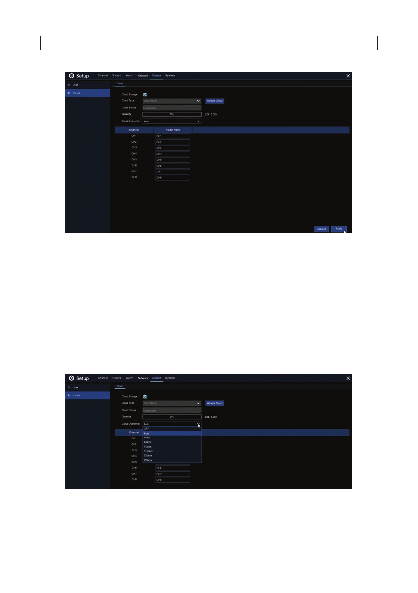
SECTION 7: DEVICE CONFIGURATION
To congure the recorder to use Cloud storage:
1. Create a Dropbox account using the same email address and password used for your recorder. Go to ww w.dropbox.com, then
follow the on-screen instr uctions for sett ing up an account.
2. Check the Cloud Storage select box to enable this feature.
3. Click Activate Cloud to activate the cloud feature.
a. Soon after wards, a message will appear that an ac tivation link was sent to your email addre ss (the email address you
used to create the Dropbox account). Check your email, and then click the link to ac tivate the settings.
b. You will be directed to the Dropbox website. Click “Allow” to nalize the activation.
4. Open the Cloud Overwrite drop down list and selec t the overwrite option you prefer.
5. Click inside the Folder Name eld for each camer a channel, and then enter a name for the camera - whatever you prefer.
6. In the Cloud menu, click Apply to save your se ttings.
54
www.Observint.com
Page 61
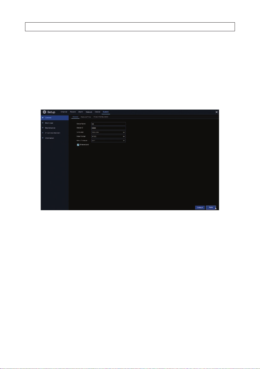
SECTION 8: SYSTEM SETTINGS
SECTION 8
System Settings
Use the System menus to congure see and congure General set tings, Multi-users, Maintenance, and display system information.
8.1 General settings
Use the System Genera menu to congure gener al settings for the system including Language, video format, recording mode, etc.
1. In the General menu shown above, congure the f ollowing:
— Device Name: Enter the preferred name for your recorder. The name can include both let ters and numbers.
— Device ID: Enter the pref erred ID for your recorder. The device ID can include only number s. This parameter is particularly
important when operating one recorder, among other recorders, with a remote control. You can identif y the target
recorder using the Device ID.
— Language: Select a language you would like the system menus to be displayed in. Multiple languages are available.
— Video Format: Select the correc t video standard for your region.
— Menu Timeouts: Click the drop-down menu to select the time your NVR will exit the Main Menu when idle. You can
also disable this by s electing OFF, which will also temporarily disable password prote ction.
— Show Wizard: Check the select box to display the Star tup Wizard when you start or reboot your NVR .
2. Click Apply to save your settings.
8.1.1 Date and Time
The Date and Time menu includes three se ctions: Date and Time, NTP Set tings, and DST Settings.
55N4, N8, N16, N32 NVR V8.1.0 User Manual
Page 62

SECTION 8: SYSTEM SETTINGS
Date & Time
1. In the Date and Time se ction, congure the following as ne eded.
— Date: Click the calendar icon to change the date.
— Time: Click the dialogue box to change the time.
— Date Format: Open the drop down list to selec t the preferred date format.
— Time Format: Open the drop down list to select the pref erred time format.
— Time Zone: Open the drop down list to selec t a time zone of your region or city.
2. Click Apply to save your settings.
NTP Settings
The NTP (Network Time Protocol) feature allows your NVR to automatically sync its clock with a time ser ver. This gives it the ability
to consistently have an accurate time set ting.
56
www.Observint.com
Page 63

3. Congure the NTP sec tion as needed
— Check the select box to enable the NTP feature.
— Select an NTP Ser ver Address from the drop down lis t.
4. Click Update Now to manually sync the date and time.
5. Click Apply to save your set tings.
SECTION 8: SYSTEM SETTINGS
DST Settings
With the Daylight Saving Time (DST) feature, you can automat ically adjust the time in the recorder when DST is in ee ct.
57N4, N8, N16, N32 NVR V8.1.0 User Manual
Page 64
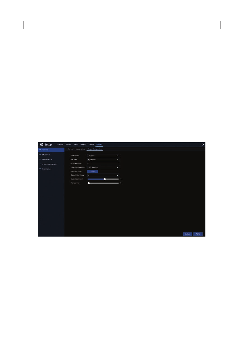
SECTION 8: SYSTEM SETTINGS
6. Congure the DST Settings menu as neede d:
— Enable DST: If DST is used in your time zone or region, check the select box to enable this option.
— Time Oset: Select the amount of time that DST chang es the time in your time zone. This refer s to the dierence
between Coordinated Universal Time (UTC) and the local time.
— DST Mode: You can select how Daylight Saving star ts and ends:
* Week: Select the month, a particular day and time when Daylight S aving starts and ends. F or example, 2 a.m. on
the rst Sunday of a particular month.
* Date: Select the s tart date (click the calendar icon), end date and time when Daylight S aving star ts and ends.
— Start Time / End Time: Set the start time and end time for Daylight Saving.
7. Click Apply to save your settings.
8.1.2 Output Conguration
This menu allows you to congure video output parameters.
1. Congure the following parameters:
— SEQ Mode: Select the s creen layout you prefer when your NVR is in s equence mode. The layout determine s how many
video channels will be displayed.
58
www.Observint.com
Page 65

SECTION 8: SYSTEM SETTINGS
— SEQ Dwell Time: Enter the time in seconds to display a video channel in se quence mode before displaying the next
video channel (300 seconds is the ma ximum).
— Output Resolution: Select a display resolut ion suitable for your monitor. 1920 x 1080 will suit most monitor. If your
recorder supports 4K output resolution, you can sele ct either 2K (2560 x 1440) or 4K (3840 x 2160).
2. Click the SETUP button to adjus t the Scale and oset of the image. Scale and oset adjust s the size and position of the display
on the monitor.
a. To adjust the scale and os et:
i. Select either Scale, X Oset or Y Oset.
ii. Click the arrows icons below to adjust the size or position of the screen.
iii. Repeat i and ii fo r other adjustments as needed.
iv. Right click anywhere on the screen to exit Scale and O set Setup.
3. Congure the following parameters as nee ded:
— Cursor Hidden Delay: Open the drop down menu to selec t the time your NVR will hide the mouse cursor when idle.
Click OFF to disable this feature and temporarily dis able password protection.
— Cursor Acceleration: To adjust the speed to move the mouse cur sor.
59N4, N8, N16, N32 NVR V8.1.0 User Manual
Page 66

SECTION 8: SYSTEM SETTINGS
— Transparency: Drag the slider lef t or right to change the transparent of the Menu Bar and the Main Menu.
4. Click Apply to save your set tings.
8.2 Multi-User setup
This menu allows you to congure the user name, password and user permission.
The system support s the following account types:
— admin: System Administrator, has full control of the system. Administrator s can change both administrator and user
passwords and enable and disable password protection.
— None: Normal User has access to Live View, Search, Playback, and other f unctions. You can setup multiple user accounts
with dierent levels of access to the system.
Change Password
To change the password f or the administrator or user account s:
1. Click the User Edit icon . Password mus t be at least 8 characters and can contain a combination of numbers and let ters.
60
www.Observint.com
Page 67

2. Enter the new password in the p assword and conrm elds
3. Click Save to save your new password.
4. In the Authentication menu, enter the OLD password, and then click Authenticate.
SECTION 8: SYSTEM SETTINGS
5. In the Multi-User menu, enable Password Enable (s trongly recommended).
Add New Users
To create a new user:
1. Select one of the user accounts that is currently disabled, and then click the User Edit icon. In the example b elow, user1 ..
user 6 accounts are disabled.
61N4, N8, N16, N32 NVR V8.1.0 User Manual
Page 68

SECTION 8: SYSTEM SETTINGS
2. In the User Edit menu, open the User Enable drop down list and then select Enable.
3. Click the User Name eld to change the user name.
4. Open the Password Enable drop down list and then select Enable (strongly recommended).
5. Enter a new password in both the Password and Conrm elds.
62
www.Observint.com
Page 69

6. Click Save.
7. In the Authentication window, enter the admin user password.
SECTION 8: SYSTEM SETTINGS
Setting User Permissions
You must login as an admin user to set the user permissions for a user. Admins can enab le or disable access to certain menus and
functions of each user account.
63N4, N8, N16, N32 NVR V8.1.0 User Manual
Page 70

SECTION 8: SYSTEM SETTINGS
Click the icon in Permission column for the user you are set ting permissions for.
8. Check the boxes nex t to any system menus or capabilitie s you want the user to use. Click All to check all boxe s. Click Clear to
check none of the boxes.
9. Click Save to save your settings.
8.3 Maintenance
In this menu you can search and view the system log, load default set tings, upgrade the system, export and import system
parameters, and congure system auto reboot.
64
www.Observint.com
Page 71

SECTION 8: SYSTEM SETTINGS
8.3.1 Log
The system lo g includes all system events, such as motion alarms and s ystem warnings. You can easily create a backup le of the
system log and copy it to a USB ash drive.
To search and backup the system log:
1. Click the calendar icons in the Star t Date and End Date elds to set the date range for the lo g messages you want to search
for.
2. Click the Start Time and End Time elds and then edit the time to s et the start time for the start date and end time for the
end date to rene the time span of your search range.
3. Open the Log Type drop down list and s elect the type of event s you would like to search. Select All to see the entire system
log for the sele cted time period.
4. Click Search.
65N4, N8, N16, N32 NVR V8.1.0 User Manual
Page 72
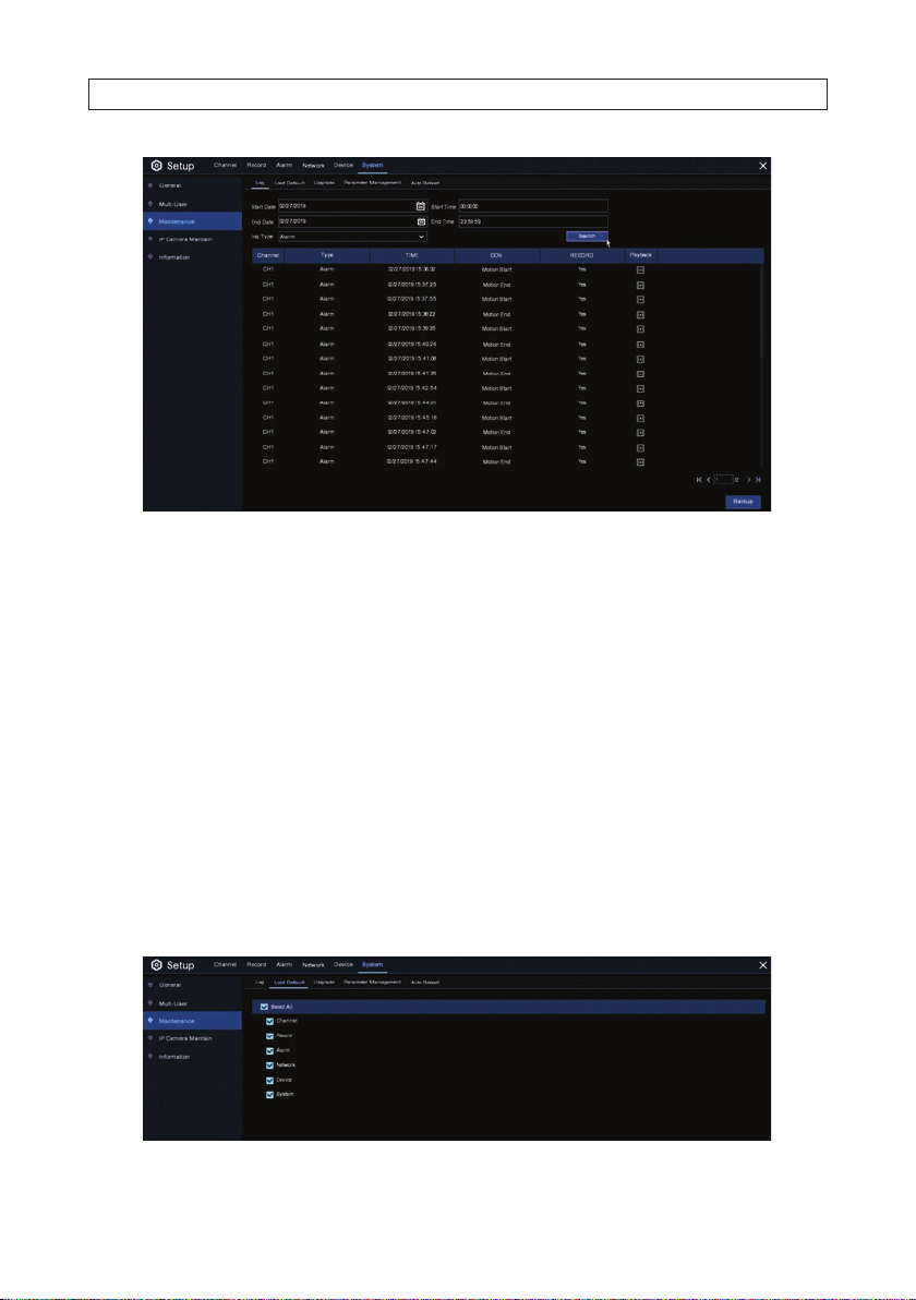
SECTION 8: SYSTEM SETTINGS
5. Browse log events lis ted in the your search result:
— Video events can be played back instantly by clicking in icon the Playback column. Right-click to return to your search
results.
— Use the icons in the lower right corner of the screen to move between pages of sys tem log events.
6. To backup the log you found:
a. Plug a ash drive for your log b ackup into a USB port.
b. Click Backup to copy the search result to a ash drive.
c. When the backup menu appears, navigate to the folder on the ash drive where you want to save the le.
d. Click OK to begin copying the le. Allow the backup operation to complete before continuing.
8.3.2 Load Default
You can reset the NVR settings to it s out-of-box state. You can reset all set tings, or just settings on specic menus. Restor ing default
settings will not delete recordings saved to the hard drive.
66
www.Observint.com
Page 73

SECTION 8: SYSTEM SETTINGS
To load defaults, che ck the items you want restore to def ault, or check Select All to choose all items, and then click Apply to load
default set tings of your chosen items. Allow the operation to complete before cont inuing.
8.3.3 Upgrade
Use the Upgrade f eature to replace the rmware in the recorder with a newer version.
1. Copy the rmware le (.sw lename extension) to a USB drive
2. Insert the USB ash drive into the USB port of the recorder.
3. In the Upgrade menu, click Selec t File button, and then select the rmware le in your USB ash dr ive. Click OK.
4. Click Upgrade to start the system upgrade. The system upgrade will last aroun d 5-10 minutes. Allow the upgrade process to
complete before continuing. Follow the on-screen ins tructions to complete the process. DO NOT power o the NVR or remove
the USB from NVR during rmware upgrade.
5. After the upgrad e process completes, remove the ash drive from the re corder.
8.3.4 Parameter Management
You can backup (Save) the main menu (sys tem conguration) settings to a USB ash drive, and then restore (Load) them later to
return the system to its former state. You can also Load the menu set tings onto another recorder (must be s ame hardware).
To Save the Main Menu settings:
1. Plug a USB ash drive with sucient space into a USB port on the recorder.
67N4, N8, N16, N32 NVR V8.1.0 User Manual
Page 74

SECTION 8: SYSTEM SETTINGS
2. Click Save Settings on the Parameter Management menu.
3. Follow the on-screen instruc tions to complete the operation. You must enter the admin user password to complete the save
operation.
4. Allow the operation to complete b efore continuing. The default name for the le you saved is DEVICE_Set tings. See below.
5. Remove the ash drive from the USB port and store it in a sec ure place for possible use later.
To Load the Main Menu settings:
1. Plug a USB ash drive containing the Main Menu Set tings you saved earlier into a USB port on the recorder.
2. Click Load Settings on the Parameter Management menu.
3. Navigate to the Main Menu Settings le you want to load and select it.
4. Follow the on-screen instructions to complete the load operation. You must enter the admin user pass word to complete the
load operation.
5. Allow the operation to complete before continuing.
6. Remove the ash drive from the USB p ort and store it in a secure place for use later.
68
www.Observint.com
Page 75

SECTION 8: SYSTEM SETTINGS
8.3.5 Auto Reboot
Use this menu to congure t he recorder to automatically reboot on a s chedule. This practice is recommended to maintain the
operational integrity of recorder.
To setup Auto Reboot:
1. Check the Auto Reb oot select box to enable this feat ure.
2. Open the Time drop down list, and then select either Every Day, Every Week , or Every Month.
3. Depending on your selec tion, use the lower menus to dene what day and time the reboot will occur.
4. Click Apply to save your set tings. You can also click Default to setup a rebo ot every Sunday at 12:00 am.
8.4 IP Camera Maintain
8.4.1 Upgrade
Use the Upgrade menu to upload a rmware le into a IP camera. To use this menu:
69N4, N8, N16, N32 NVR V8.1.0 User Manual
Page 76
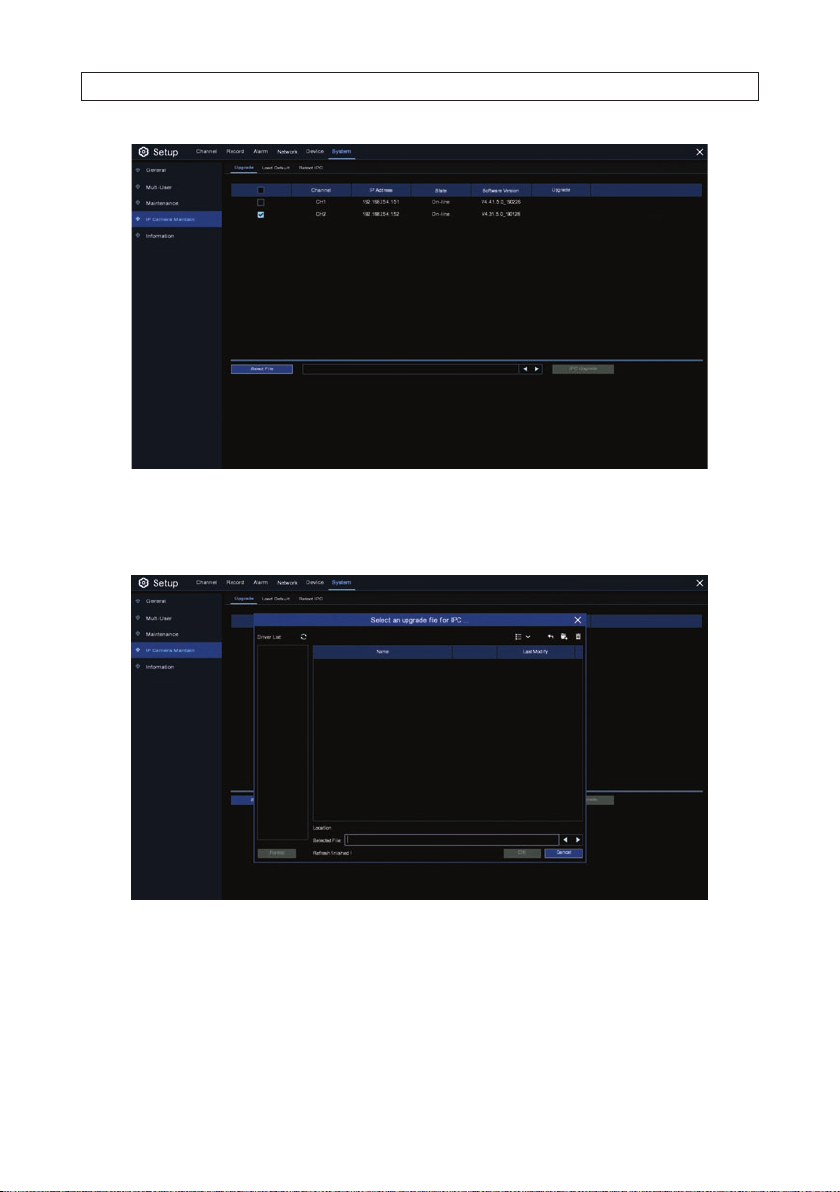
SECTION 8: SYSTEM SETTINGS
1. In the list of IP camer a channels, check the select b ox for the IP camera you want to upgrade.
2. Click Select File. In the Selec t an upgrade le .... screen, locate and then select the r mware le you need for the
Upgrade, and then click OK.
3. In the Upgrade menu, click IPC Ugrade to install the new rmware. You may be required to enter the admin user pass word to
initiate the upload. Allow the operation to complete before continuing.
8.4.2 Load Default
Use this menu to rese t an IP camera to its factor y default state . To use this menu:
70
www.Observint.com
Page 77

SECTION 8: SYSTEM SETTINGS
1. Check the sele ct box for the camera(s) you want to reboot.
2. Click Load Default. You may be required to enter the admin user pas sword to initiate the upload. Allow the op eration to
complete before continuing.
8.4.3 Reboot IPC
Use this menu to reboot an IP camera. To use this menu:
1. Check the sele ct box for the camera(s) you want to reboot.
2. Click Reboot Camera. You may be required to enter the admin user password to initiate the reboot operation. Allow the
reboot to complete before cont inuing.
8.5 Information
The Information menus show impor tant conguration data about the recorder. Use it to show system information, channel
information, record information and network status.
71N4, N8, N16, N32 NVR V8.1.0 User Manual
Page 78

SECTION 8: SYSTEM SETTINGS
If your NVR suppor ts P2P, you will nd t he P2P ID and P2P QR code in the information page. You can scan this QR cord with mobile
app to congure the app for remote viewing of the NVR.
8.5.1 Channel Information
Used the Channel Inf ormation screen to see the mainstream and subs tream recording conguration, motion detection status and
other parameter s for each IP camera monitored by the system.
8.5.2 Record Info
Use the Record Info screen to see t he recording information for each connected camera. This info rmation includes the bitrate,
stream type, recording res olution and frame rate (FPS), and other parameters.
72
www.Observint.com
Page 79

8.5.3 Network Status
The Network Status screen includes a summar y of all network settings.
SECTION 8: SYSTEM SETTINGS
73N4, N8, N16, N32 NVR V8.1.0 User Manual
Page 80

SECTION 9: SEARCH, PLAYBACK, BACKUP AND TAGS
SECTION 9
Search, Playback, Backup and Tags
Using Search feature s you can nds and playback previously re corded videos and snapshots t hat are stored on the HDD. Using the
Backup feature you can save video and snapshots to a USB ash dr ive.
9.1 Using Search Features
Open the Start menu and clic k the Search button to open the Search mo de menu.
Search Type
Search OptionsSearch Date
Channel selection Video Playback Controls Timeline
Playback Status
Time frame options
The Search menu includes the following:
• Search Options: the system provides various search & playback methods: General, Event s, Sub-periods, Smart & Pic tures
• Search Date: search by a date to play back.
• Search Type: the system provides dierent search t ypes to narrow your search.
• Channel Selection: to choose the channels you want to searc h & play.
• Video Playback Controls: to control the video playback .
74
www.Observint.com
Page 81

SECTION 9: SEARCH, PLAYBACK, BACKUP AND TAGS
Enlarge
— Enlarge: the video playback to full sc reen
— Rewind: x2, x4, x8 and x16
— Slow Play: 1/2, 1/4 and 1/8, 1/16 speed
— Play
— Pause
— Play by frame: Click once to play a frame of the video
— Fast Forward:, x2, x4, x8 and x16
— Digital Zoom: Click to zoom in then click-and-drag on a camera image during playback to zoom in on the selected area.
Slow play Fast forward
Rewind Stop
Video clipPlay by frame
Digital zoomPause
Add Default Tag
Volume control Add Custom Tag
Right-click to return to regular playback.
— Video Clip: Quickly save a section of video to a USB ash drive.
— Volume Control: scroll the slider bar to inc rease or decrease volume.
— Snapshots: To capture a snapshot image to your USB ash drive. If t he video playback is in split-screen view, move the
mouse cursor to the channel you want to c apture, and then click the icon to save the snapshot.
— Add Default / Custom Tag: Click to assign a name to the video clip. The clip can then be searched for by tag name.
• Timeline: Continuous recordings are shown with colored bars to repre sent dierent types of recording (legend show n in the
bottom-right corner of the display). Use the time frame opt ions to view a smaller or larger time period.
Dierent types of recording shown in dierent color s:
— Continuous Recording in Green color
— Motion Recording in Yellow color
— I/O Recording in Red color
— Motion & I/O Recording in Orange color
— Intelligent Recording in Blue color
— PIR Recording in Purple color
• Playback Status: display the video play status
9.1.1 Search, Playback and Backup video
Click the General option at the top of the Search screen. To search and play recorded video, open the Star t menu and click the
Search button. A sc reen somewhat like that shown below will app ear.
75N4, N8, N16, N32 NVR V8.1.0 User Manual
Page 82

SECTION 9: SEARCH, PLAYBACK, BACKUP AND TAGS
1. Click the calendar icon in the Date eld, and then select the date to search for vide o recording. Dates marked with a red
underline have recorded video.
2. Check the select boxes for the search t ype you want to perform.
3. Check the selec t boxes for the camera channels you would like to search, or check Channel to search all channels with
cameras.
4. The search result will display automatically on the timeline from 00:00 to 24:00.
5. Click the Play icon but ton to start playback. You can control other playback f unctions with other but tons on Video Playback
Controls.
6. Use the time frame options to expand or cont ract the timeline to see more or less detail.
7. If you want to save a section of v ideo during playing back:
a. Plug a USB ash drive into a USB port on the controller
b. Play back the video you want to backup.
c. Click the Vide o clip icon.
d. Check the channel(s) you want to include in your video clip backup.
e. Move the mouse curs or to the timeline where you want to star t the video clip.
f. Press and hold the left but ton of your mouse, and then drag the cur sor to the timeline where you want to end the v ideo
clip.
g. The Clip icon will change to a Backup icon. Click the Backup icon to save the video clip.
h. Select a le type for your backup les.
76
www.Observint.com
Page 83

SECTION 9: SEARCH, PLAYBACK, BACKUP AND TAGS
i. On the Backup Type menu, notice the size of the backup le. Make sure your USB drive has enough free space to
accommodate the le.
j. Click Save.
k. When the backup drive menu appears, navigate to the folder where you want to save the le.
l. Click OK to begin. The progress bar at the bottom of the window shows you the progress of the backup.
77N4, N8, N16, N32 NVR V8.1.0 User Manual
Page 84

SECTION 9: SEARCH, PLAYBACK, BACKUP AND TAGS
m. Allow the backup operation to complete before continuing.
n. Click OK to close the Backup window. Remove your USB ash drive from the recorder.
9.1.2 Event Search, Playback and Backup
Click the Events option at the top of the Search screen. Use Event search is used to search for event triggered recordings during a
time frame. You can easily back up the recording to a USB ash drive.
Search Type
Search Date / Time
Channel selection
Search button Page controls
File statisticsBackup Play iconEvent info
View options
To search, play & back up for events:
1. Choose the date and time you want to search.
2. Check the recording ty pes you want to search, or check Search Type to choose all.
3. Choose the channels you want to s earch, or check Channel to choose all channels.
4. Click the Search button to st art search.
5. Events tting your search criteria are displayed in list form. You can double click the on one of the events to play the video of
that event.
6. Click icons in the bottom-r ight corner of the menu to browse bet ween pages of events, or enter the page you want to browse.
78
www.Observint.com
Page 85

SECTION 9: SEARCH, PLAYBACK, BACKUP AND TAGS
7. You can click the View option icons to switch the view to lis t form. Select either :
— List view: You can view the snapshots of the events.
— Thumbnail view
— Detailed view: In the de tailed view mode, you can lock the video clips to keep them from being over written on the HDD.
Click the icon to lock or unlock the clip.
When you click on a vide o clip, the system will show the event infor mation on the left bot tom corner of the screen.
8. To select video clips, check the selec t box to select one video clip, or check the box nex t to Select to selec t all event clips in the
page. The number of selected les and total size information will be displayed at the right bot tom of the screen.
9. To backup the les you selected, click the Backup icon to save the video to USB ash drive, or click the Play icon in playback
controls to play the video(s).
9.1.3 Event Playback Control
The Search screen appears as that shown below during playback.
Event list for playback
Video Playback ControlsLegendPlay recordingBackup Timeline Timeframe options
Items in the screen above include:
• Event List: Click on the event to play, and check the select box for backup
• Use the Backup and Play recording icons as needed.
• Video Playback Controls: See “9.1 Using Search Features” on page 74. Click the rst icon to exit playback mo de and
return to the Search menu.
• Timeline shows the The event you are playing now will be displayed on the timeline.
• Use the timef rame options to expand (for more de tail) or compress the timeline.
79N4, N8, N16, N32 NVR V8.1.0 User Manual
Page 86

SECTION 9: SEARCH, PLAYBACK, BACKUP AND TAGS
9.1.4 Sub-periods Playback
Click the Sub-periods option at the top of the Search screen. Sub-periods playback allows you to play multiple normal re cordings
and motion events simultaneously f rom a single channel. With normal and event recordings, the video is divided evenly depending
on the split-screen mode that has be en selected. For example, if the video is an hour long and you have selec ted Split-screens x 4,
each split-screen will play for 15 minutes.
NOTE
Search Date
The NVR may not be able to displ ay high megapixel cameras (such as 4K video) across four sub -periods. Refer to the Speci cations
for your recorder for mo re information on display capa city.
Screen split number
Channel selection Video Playback Controls Timeline
Search Type
Split screens
Time frame options
To search and play video in sub-periods:
1. Congure the date and time you want to search.
2. Selec t the split-screens you want the videos to be played in.
3. Sele ct the recording type s you want to search, or check Search Type to choose all.
4. Select the channel you want to search. Note: This feature suppor ts to search and playback of one channel at a time.
5. Click t he Play button to start playb ack. Control the playback with buttons on Video Playback Controls. Videos are being played
in split-screens. When you left click on a particular split-screen, the time perio d of the video you clicked on will be displayed on
the timeline. The color bar on top of the timeline indicates the time span of the video split-screen you have clicked. The color
bar on the bot tom of the timeline indicates the time sp an for the whole videos you have searched.
6. Use the timeframe options to expand (for more detail) or compress the timeline.
80
www.Observint.com
Page 87
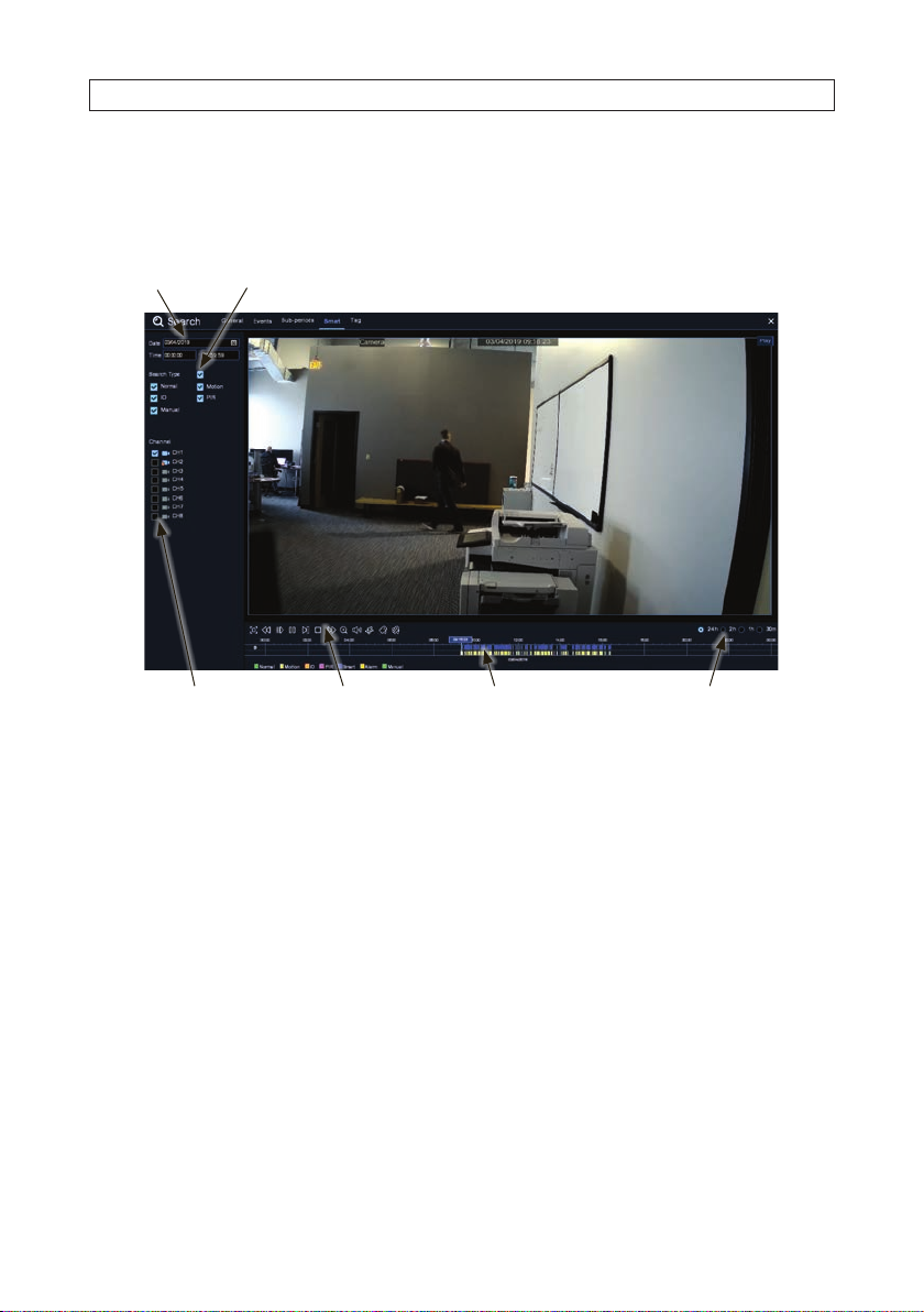
SECTION 9: SEARCH, PLAYBACK, BACKUP AND TAGS
9.1.5 Smart Search and Playback
Click the Smart option at the top of the Search screen. Smar t mode allows you to easily search and play the motion e vents in one
or more specic areas of the channel.
Search Date
Channel selection Video Playback Controls Timeline
Search Type
Time frame options
To start a smart search and playback :
1. Congure the date and time you want to search.
2. Selec t the recording types you want to search, or check S earch Type to choose all.
3. Sele ct the channel you want to search, the motion recording in the selected channel will be searche d automatically. Please
note that this function only supports to search and play one channel at a time.
4. Click the Play button to start playback. Control the playback with buttons on Video Playback Controls. The color bar on the top
of the timeline indicates the time span of the recordings you s earched for. The color bar on the bottom of the timeline indicates
the complete time sp an for the recordings you specied.
5. Use the timeframe options to expand (for more detail) or compress the timeline.
9.1.6 Smart Search Area
The smart searc h feature searches for motion in the entire eld of view by default. For eciency, you can specify one or more areas
to narrow your search. To enter Smar t search mode, click the Smart search icon on Video Playb ack Controls.
81N4, N8, N16, N32 NVR V8.1.0 User Manual
Page 88

SECTION 9: SEARCH, PLAYBACK, BACKUP AND TAGS
Enlarge
Slow play Fast forward
Rewind Stop
Play by frame Volume control
Add Default Tag
Digital zoom Add Custom Tag
Smart searchPause
After clicking the Smart search icon, camera video will exp and to full screen and the Smart controls bar will be visible.
Smart Search area selected
Full screen detection Return to Playback
Delete areas created
Search / Play video found
To dene one or more speci c areas, do the following:
1. Click and drag the mouse cursor across the area you want to s earch. You can dene multiple areas. In the example shown
above, the area in the middle without the gr id was selected for Smar t search. You can also use the same action to delete areas
you selected.
2. Click the Search icon to return to the Playb ack menu and play video(s) found for areas you selec ted. Blue marks will appear on
the timeline indicating video that matches your search criteria.
82
www.Observint.com
Page 89
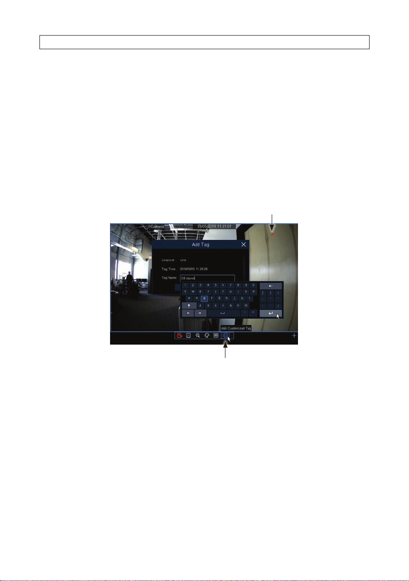
SECTION 9: SEARCH, PLAYBACK, BACKUP AND TAGS
9.1.7 Tags
The Tag feature is used to assign a descriptive name to a recording. The tagged recordings can then be easily found, replayed and
backed up if nee ded.
Tags can be assigned to recording during playbac k, and in the Live screen when the Live video is being re corded. You can also edit
the tag name later.
Create a tag during Live view
To create a tag during Live view :
1. In Live view, click on the Live view frame you want to tag. If the video is not being recorded (no record icon in the upper right
corner of the frame), click on the Manual Record icon to b egin recording.
Record in progress icon
Add Customized tag
2. Click on the Add Customized Tag icon on then Quick Set ting Toolbar.
3. In the Add Tag popup window, click OK, or edit the Tag Name eld, and then click OK.
Create a tag during Playback
To create a tag during Playback of a video recording, click on the Add Def ault Tag icon in the play control toolbar, or click on the
Add Customized Tag icon and then enter a Tag Name in the popup window.
83N4, N8, N16, N32 NVR V8.1.0 User Manual
Page 90

SECTION 9: SEARCH, PLAYBACK, BACKUP AND TAGS
Click Save in the A dd Tag window to save the tag name.
Search for Tags
To nd tagged recordings:
1. Open the Search window.
2. Click the Ta g tab.
Select Start / End date and time
Search result - tag list
Add Customized TagAdd Default Tag
Click Search icon Play icon
84
www.Observint.com
Page 91

SECTION 9: SEARCH, PLAYBACK, BACKUP AND TAGS
3. Sele ct the date and time range in the lef t panel to encompass when the tag was created. See above.
4. Click the Search button. A lis t of entries will appear showing the tags created at that time range.
5. To play a tagged recording, double click on the entr y in the list.
Edit icon
6. To edit the tag name, click the edit icon for the tag name you want to c hange.
7. To quickly nd a recording with a specic tag name, enter the tag name in the Keyword eld, and then click t he Search
button. In the example below, intruder was entered in the keyword eld.
Search button
85N4, N8, N16, N32 NVR V8.1.0 User Manual
Page 92

SECTION 9: SEARCH, PLAYBACK, BACKUP AND TAGS
The Search result is shown in the char t.
86
www.Observint.com
Page 93

SECTION 10: REMOTE LOGIN
SECTION 10
Remote Login
Use the Web Client to remotely access your NVR at any time via a PC. Before you acces s the Web Client, you need to ensure that the
internet set tings of the NVR are congured properly.
10.1 System Requirements
The minimum requirements for hardware and OS required to run Web Client are given as below.
Item Minimum Recommended
CPU Intel® Core™ i5 C PU Intel® Core™ i5 C PU or higher
RAM 4GB o r more 8GB or more
Hard Drive 500GB or m ore 1000GB o r more
Displa y RAM 2GB or more 4GB or mor e
Display Resolution 128 0 × 1024 1920 × 1080
OS Windows 7 o r above, Mac OS X® 10.9 or ab ove
DirectX Di rec tX 11
Direct3D Acceleration Function
Ethernet Adapter 10/100/1000M Ethernet Adapter
©
IE Microso ft Interne t Explorer ( Ver. 11, 10, 9, 8). It does not suppo rt Microso ft
Apple S afari 5.1 or abov e
Edge.
10.2 Remote login
NOTE
Important notes ab out remote login:
• Remote login to the recorder requires Microsoft
• You must install Survei llancePlugin.exe to fully use the features of the recorder’s Internet interface. Usually this is only installe d
once, but if a newer version is released, a reinstall may be necessary.
• If your computer is on the same network (router) as your recorder, you can usually use the IP addre ss of the recorder for the IE
URL.
• The recorder feat ures UPnP. If your router also suppor ts this feature, it may be ver y easy to setup port for warding in your router
for access to the recorder from outside the router’s rewall (the Internet).
The instructi ons and screen shots included herein fo r an initial login to the NVR use a Microsof t Windows 7 system. If using a
Windows 10 or an Apple i OS system, the instructions are sim ilar.
©
Internet Explorer© (IE ).
87N4, N8, N16, N32 NVR V8.1.0 User Manual
Page 94

SECTION 10: REMOTE LOGIN
10.2.1 Remote login with Surveillance Plugin installation
To log into the recorder:
1. Open the IE brows er.
2. Use the appropriate URL to connect to your recorder. If your PC is on the same L AN as your recorder, usually you can use the IP
address of the re corder as the URL f or your browser.
3. If the p lugin Surveil lancePlugin.exe (SurveillanceClient.dmg on iOS) was not previously installed on your PC:
a. The recorder will prompt you to install the plugin. When the following screen appear s, click the download link.
b. In the footer bar, when the Run, Save or Cancel opt ions appear, click Save.
c. Allow the download to complete, and then op en your IE download director y and nd the plugin le.
88
www.Observint.com
Page 95

d. Close the IE browser, and then double-click on the plugin le to execute it.
SECTION 10: REMOTE LOGIN
e. Clic k Install in the setup wizard window, wait until the plugin installation completes. Follow the on screen instructions.
4. Open an IE browser window enter the same URL as before. If the plugin installation was successful, an authentication window
will appear.
89N4, N8, N16, N32 NVR V8.1.0 User Manual
Page 96
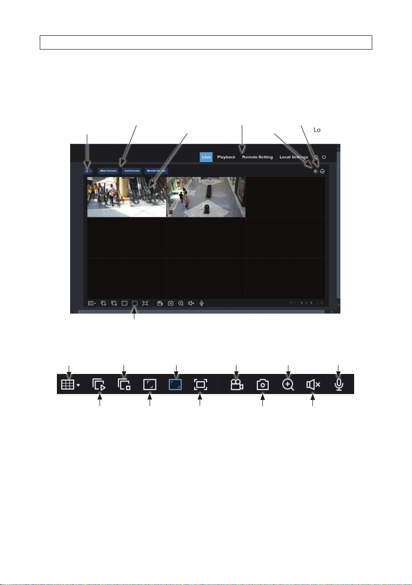
SECTION 10: REMOTE LOGIN
5. In the authentication window, enter your user name and p assword as shown above, and then click Login. The Live window
will open.
10.3 Live screen
Channel Live View frames (16)Open Channel List
Open Channel List
Live Toolbar
Main Menu Tabs
Color adjust
PTZ controlsStream select
Logout
Live View toolbar
Screen split
Close all channels Digital zoom Mic enable
Open all channels Original proportion
1. Double-click on a channel frame to expand the image to full fr ame.
90
www.Observint.com
Stretch
Record On/O
SnapshotEnlarge
Volume / Mute
Page 97

SECTION 10: REMOTE LOGIN
2. Click on a camera to adjust, and t hen click the Color adjust icon. Balance the screen color s using the sliders in the Color frame
as needed for your monitor.
3. Click the Channel list icon. In the list that opens, you can start and stop manual recording, capture an image, and sele ct
bitrate for the channel.
91N4, N8, N16, N32 NVR V8.1.0 User Manual
Page 98

SECTION 10: REMOTE LOGIN
Record Capture
Bitrate
4. If you have a PTZ camera in the sur veillance system, select the camera in the Live screen, and then click the PTZ icon to selec t
it.
10.4 Playback screen
Open the Playback s creen by clicking the Playback tab. You can playbac k recorded video from up to four channels at a time. Controls
and options for the remote Playback screen are very similar to the console Search s creen. For more information, see: “9.1 Using
Search Features ” on page 74.
92
www.Observint.com
Page 99

SECTION 10: REMOTE LOGIN
10.5 Remote Settings
Open the Remote Se ttings screen by clicking t he Remote Settings tab. Click the links in the left p anel to open the menu for that
item. For more information about items in the menu, ref er to the descriptions of the rmware menus earlier in this manual.
93N4, N8, N16, N32 NVR V8.1.0 User Manual
Page 100
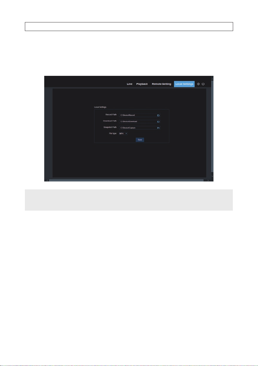
SECTION 10: REMOTE LOGIN
10.6 Local Settings
Open the Local S ettings screen by clicking the Local Settings tab. Items in this menu congure the direc tories on your local
computer where you want to save record, download and capture les, and the format of re cord and capture les to save.
If attempts to ma ke changes to the Local Set tings directories fails:
NOTE
• Run Microsoft I E in administrative mode.
• Add the URL of the recorder to th e Trusted list in IE.
94
www.Observint.com
 Loading...