

Observint ECO4IR, ECO4LCD, ECO4IR2, ECO4IRPROMO, ECO4LCD2 Installation Instructions Manual
ECO4 4-Camera H.264 Day/Night Security System
Installation and Setup Guide
Products: ECO4IR, ECO4IR2, ECO4LCD, ECO4LCD2, ECO4IRPROMO
ECO4LCD2 System
PLEASE READ THIS MANUAL BEFORE USING YOUR SYSTEM, and always follow the instructions for safety
and proper use. Save this manual for future reference.
ECO4_SQ
11/20/2013
ii
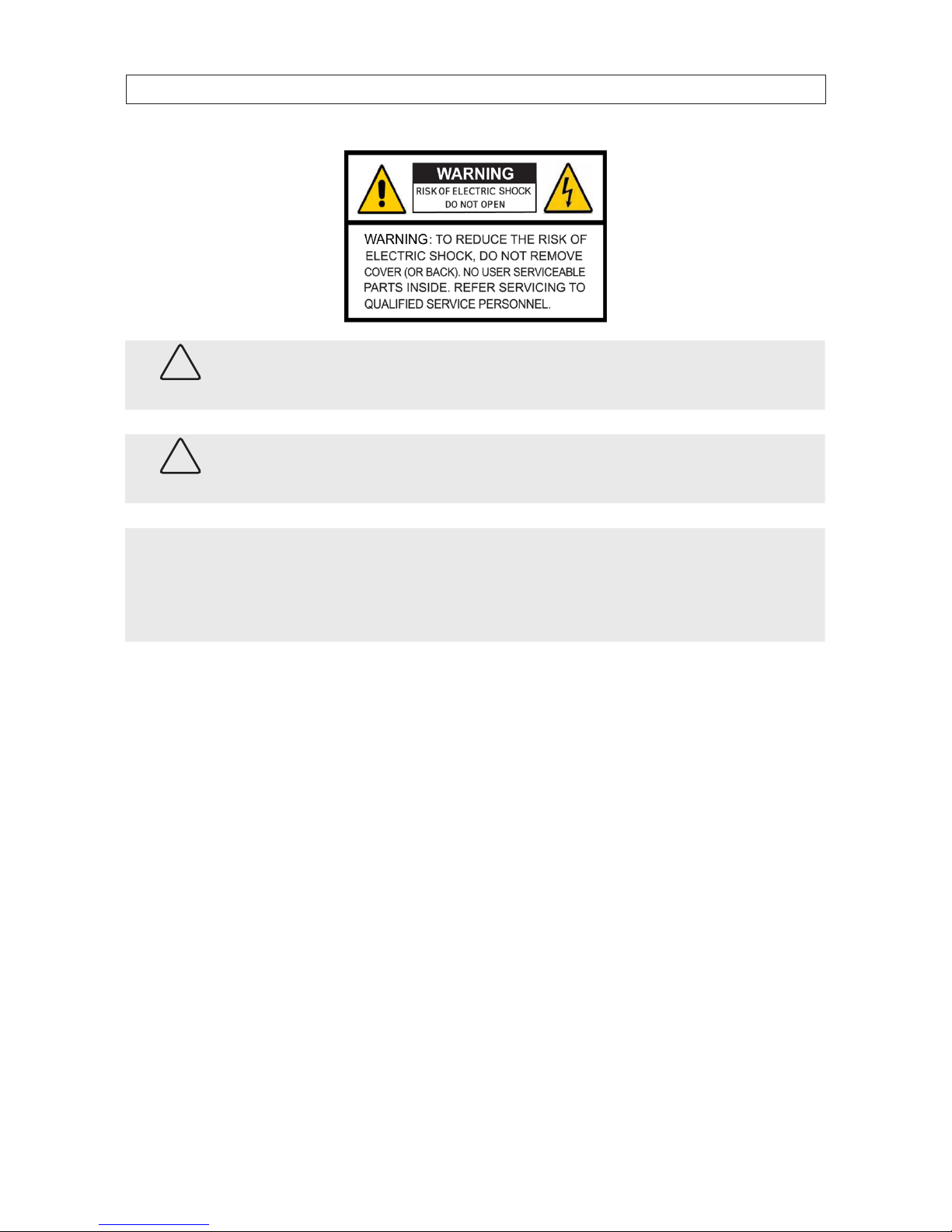
CAUTION
Do not expose this appliance to rain or moisture. Operate this device only in environments where the temperature or
humidity is within the recommended range. Operation at extreme temperatures or in very high or low humidity levels
may cause electric shock and shorten the life of the product.
CAUTION
FCC Caution: To assure continued compliance, use only shielded interface cables when connecting to computer or
peripheral devices. Any changes or modications not expressly approved by the party responsible for compliance could
void the user’s authority to operate this equipment.
NOTE
This equipment has been tested and found to comply with the limits for a Class “A” digital device, pursuant to Part 15
of the FCC Rules. These limits are designed to provide reasonable protection against harmful interference when the
equipment is operated in a commercial environment. This equipment generates, uses, and can radiate radio frequency
energy and, if not installed and used in accordance with the instruction manual, may cause harmful interference to radio
communications.
LEGAL NOTICE
Observint Technologies (Observint) products are designed to meet safety and performance standards with the use of
specic Observint authorized accessories. Observint disclaims liability associated with the use of non-Observint
authorized accessories.
The recording, transmission, or broadcast of any person’s voice without their consent or a court order is strictly
prohibited by law.
Observint makes no representations concerning the legality of certain product applications such as the making,
transmission, or recording of video and/or audio signals of others without their knowledge and/or consent. We
encourage you to check and comply with all applicable local, state, and federal laws and regulations before
engaging in any form of surveillance or any transmission of radio frequencies.
Microsoft, Windows, and Internet Explorer are either registered trademarks or trademarks of Microsoft Corporation in
the United States and/or other countries. Android is a trademark of Google Inc. Use of this trademark is subject to
Google Permissions. Apple, iPhone, iPod touch, and iPad are registered trademarks of Apple Inc.
Other trademarks and trade names may be used in this document to refer to either the entities claiming the marks
and names or their products. Observint disclaims any proprietary interest in trademarks and trade names other than
its own.
No part of this document may be reproduced or distributed in any form or by any means without the express written
permission of Observint, Inc.
© 2013 by Observint Technologies. All Rights Reserved.
11000 N. Mopac Expressway, Building 300, Austin, TX 78759
For Sales and Support, contact your distributor.

iii
4-Camera H.264 Security System Setup Guide
SAFETY INSTRUCTIONS
Safety Instructions
Read these instructions and keep them in a safe place for future reference.
• Please refer all work related to the installation of this product to qualied service personnel or system installers.
• Do not operate the appliance beyond its specied temperature, humidity or power source ratings.
• Place the unit on a at surface not prone to vibration or impact.
• Use the appliance at temperatures between 32 °F ~ 113 °F (0 °C ~ +45 °C) and relative humidity below 85%. The input
power source for this appliance is between 90 ~ 264 Vac, 47 ~ 63 Hz.
• Install the unit away from heat sources such as radiators, heat registers and stoves.
• Installation of the unit near consumer electronics devices, such as stereo receiver/ampliers and televisions, is permitted as long
as the air surrounding the terminal does not exceed the above mentioned temperature range.
• Handle hard disk drives with care.
— It is possible to damage hard drives if they are moved while their motors are still running. To allow the hard drive to spin
down and park its heads, wait at least 10 seconds after disconnecting power before moving the unit.
— To avoid shock and vibration damage to the internal hard drive, do not move the unit while it is plugged in.
— Protect hard disk drives from static electricity.
— Do not stack hard disk drives or keep them upright.
— Do not use an electric or magnetic screwdriver to x hard disk drives.
• Do not place the unit in an enclosed area where the cooling vents are blocked or impede the ow of air through the ventilation
openings.
• Protect the power cord from being stepped on or pinched particularly at plugs and the points where they exit from the
apparatus.
• Do not drop metallic parts through slots. This could permanently damage the appliance. Turn the power o immediately and
contact qualied service personnel for service.
• Handle the appliance with care. Do not drop or shake, as this may damage the device.
• Do not expose the appliance to water or moisture, nor try to operate it in wet areas. Do not install the unit in an area where
condensation occurs. Do not operate with wet hands. Take immediate action if the appliance becomes wet. Turn the power o
and refer servicing to qualied service personnel. Moisture may damage the appliance and also cause electric shock.
• Do not use strong or abrasive detergents when cleaning the surfaces of this product. When dirt is hard to remove, use a mild
detergent and wipe gently.
• Do not overload outlets and extension cords. Electric shock or re may result.
• Save your system conguration.
• Distributing, copying, disassembling, reverse compiling, reverse engineering, and exporting, in violation of export laws, the
software provided with this product is expressly prohibited.

iv
TABLE OF CONTENTS
Table of Contents
SECTION 1 Systems Overview ................................................................... 1
1.1 Controls, connectors and indicators .....................................................2
1.2 Cameras ............................................................................5
SECTION 2 Installing the System ................................................................6
2.1 Getting Started: Unpacking the Equipment ..............................................6
2.2 Camera installation ..................................................................6
2.2.1 Camera placement ...............................................................7
2.2.2 Mounting ......................................................................8
2.3 Install and setup a monitor ............................................................9
2.4 DVR installation .....................................................................9
2.4.1 Placement ......................................................................9
2.5 Connecting the components together ..................................................10
2.6 Adjusting the camera ................................................................11
SECTION 3 System Setup ......................................................................13
3.1 Login to the DVR ...................................................................13
3.2 Conguring the system ..............................................................14
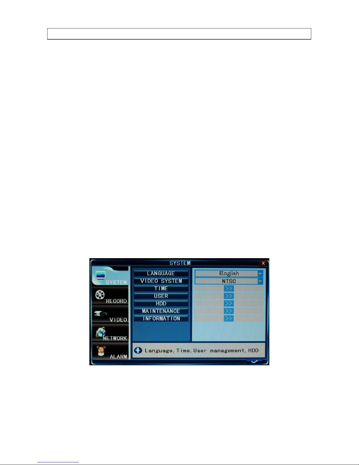
3.2.1 Setting the screen language and video system format ................................15
3.2.1 Setting the system time .........................................................15
3.2.2 Change the Admin and user1 passwords ...........................................17
3.2.3 Add uses to the system ..........................................................18
3.2.4 Set HDD overwrite option ........................................................19
3.3 Record conguration settings .........................................................20
3.4 Video conguration settings ..........................................................22
3.4.1 Video setup ....................................................................23
3.5 Network conguration settings .......................................................25
3.6 Alarm conguration settings .........................................................25
3.6.1 Motion detection setup .........................................................27
SECTION 4 Networking Your DVR ...............................................................30
4.1 Congure the DVR for access on your home network. . . . . . . . . . . . . . . . . . . . . . . . . . . . . . . . . . . . . .31
4.1.1 Verify local network connectability with IE .........................................36
4.2 Accessing your DVR from the Internet ..................................................40
SECTION 5 Accessing Your DVR With a Web Browser ...............................................43
5.1 Connecting to your DVR with IE .......................................................43

v
4-Camera H.264 Security System Setup Guide
TABLE OF CONTENTS
5.2 Live screen .........................................................................44
5.3 Replay window .....................................................................45
5.4 Remote window ....................................................................45
5.5 Local setting .......................................................................46
5.6 Logout ............................................................................47
5.7 Accessing the DVR with Mozilla® Firefox® or Google Chrome™ browsers .....................47
SECTION 6 KWeye Smartphone App ............................................................48
6.1 Installing KWeye ....................................................................48
6.1.1 Installing KWeye in iPhone .....................................................48
6.1.2 Installing KWeye in Android .....................................................50
6.2 Set up access to a DVR ...............................................................50
6.3 Using KWeye .......................................................................51
SECTION 7 DVR System Menus .................................................................53
7.1 Menu tree .........................................................................53
7.1.1 Tool Bar .......................................................................54
7.1.2 Menu options ..................................................................54
7.2 System menu. . . . . . . . . . . . . . . . . . . . . . . . . . . . . . . . . . . . . . . . . . . . . . . . . . . . . . . . . . . . . . . . . . . . . . .55
7.2.1 Language .....................................................................55
7.2.2 Video System ..................................................................56
7.2.3 Time Setup ....................................................................56
7.2.4 User management ..............................................................56
7.2.5 HDD ..........................................................................58
7.2.6 Maintenance ...................................................................59
7.2.7 Information. . . . . . . . . . . . . . . . . . . . . . . . . . . . . . . . . . . . . . . . . . . . . . . . . . . . . . . . . . . . . . . . . . . .61
7.3 Record ............................................................................61
7.3.1 Record Channel ................................................................62
7.3.2 Record ........................................................................62
7.3.3 Bit-rate .......................................................................62
7.3.4 Resolution ....................................................................62
7.3.5 Frame Rate ....................................................................62
7.3.6 Packtime ......................................................................62
7.3.7 Record Mode ...................................................................63
7.4 Video .............................................................................64
7.4.1 Video Channel .................................................................64
7.4.2 Name .........................................................................64

vi
TABLE OF CONTENTS
7.4.3 Position .......................................................................64
7.4.4 Live ..........................................................................64
7.4.5 Color .........................................................................64
7.4.6 Record Time ...................................................................65
7.4.7 Margin ........................................................................65
7.4.8 Video Setup ...................................................................65
7.5 Network ...........................................................................66
7.5.1 Network Setup .................................................................66
7.5.2 DDNS Setup. . . . . . . . . . . . . . . . . . . . . . . . . . . . . . . . . . . . . . . . . . . . . . . . . . . . . . . . . . . . . . . . . . . .68
7.5.3 Email Setup ....................................................................69
7.5.4 Mobile Monitor ................................................................70
7.6 Alarm .............................................................................71
7.6.1 DURATION .....................................................................71
7.6.2 BUZZER .......................................................................71
7.6.3 PRERECORD ....................................................................71
7.6.4 EXCEPTION ....................................................................71
7.6.5 Motion Detection ...............................................................72
SECTION 8 Cleaning ..........................................................................74
APPENDIX A O-loaded Video Files ..............................................................75
APPENDIX B Specications .....................................................................76

1
4-Camera H.264 Security System Setup Guide
SECTION 1: SYSTEM OVERVIEW
SECTION 1
Systems Overview
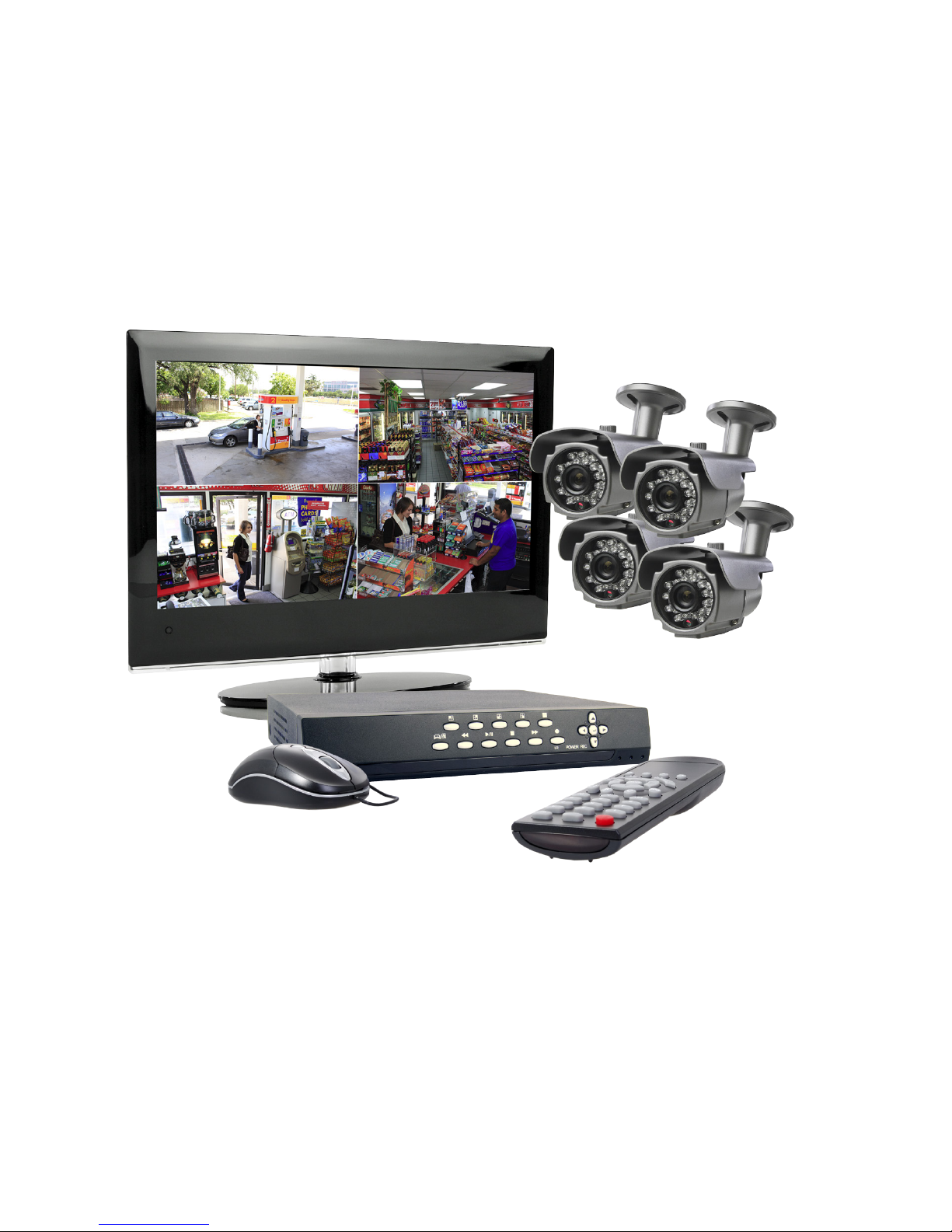
Congratulations on purchasing your 4-camera H.264 security system! Your system includes:
• 4–camera networkable digital video recorder (DVR) with a pre-installed 500 GB hard drive.
• Local conguration and control using the operator control panel and mouse, or remote access and control through the
Microsoft® Internet Explorer® (IE) browse.
• State-of-the-art H.264 compression technology to maximize your recording time, optimize your video quality, and minimize
hard drive space. Data stored in the DVR can easily be o-loaded via USB or across your network.
• Apple® iPhone®, iPad®, and iPod Touch®, Google Android™, Symbian™, Windows® Mobile, and Blackberry® smartphones apps
that let you monitor your home or business on the go from almost anywhere.
• LCD 17” monitor (with ECO4LCD and ECO4LCD2 systems only)
Cameras
5-way Splitter
Mouse
Remote Control
Video/Power
Extension Cables
DVR
Power Adapter
ECO4IR2 system components
2
1.1 Controls, connectors and indicators
Your new security system is easy to use and easy to setup. This section includes the function and use of the components included
with a ECO4IR system. For installation instructions, refer to Section 2. System setup, including advanced control and conguration
procedures, is included in Section 3.
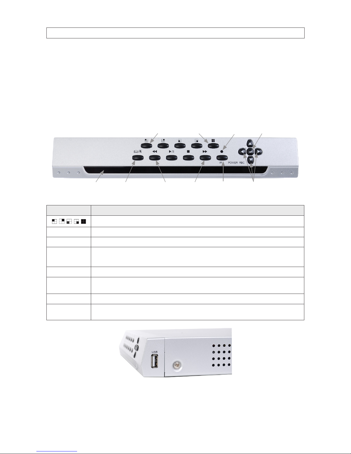
ECO4 DVR Front Panel
Single/Multi Camera Display Select
tqpu Menu
Navigation Buttons
MenuLED Indicator|
Panel
Enter
Video Playback Controls
Infrared
Sensor
Power/
Record
Button Usage
Selec t any single camera channel (channel 1, 2, 3, or 4 )to display, or select the 4-channel display.
Infrared Sensor Sensor for the remote control.
Enter Press to conrm a menu choice.
t q p u
Use arrow butto ns to move among the menu items. Press Enter ( 8 ) to conrm your choice. Use these buttons to navigate through
the menu s ystem. Generally, use the t u b uttons to move to selec tion boxes, and use q p to select submenu parameters.
POWER/REC Use to power on the DVR, and star t and stop manual recording.
Video Playback
Controls
Standar d controls for playing back a selected video track. u/II: Opens video search and play back menu. When t he playback mode
is activated, press this button to play/pause playback.
MENU Opens t he main menu window
USB
Side panel USB 2.0 por t (see below). This p ort can be used for a por table mobile HDD, ash drive, DVD burner, rmware upgrade,
etc. Note: Connect the mouse to the USB por t on the back panel.
Side Panel
USB Port
SECTION 1: SYSTEM OVERVIEW
3
4-Camera H.264 Security System Setup Guide
SECTION 1: SYSTEM OVERVIEW
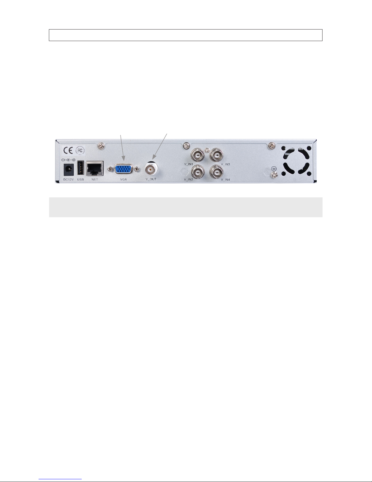
DVR Backpanel
CH1 - CH4
Video In
LAN
Monitor Out
(BNC)
Monitor Out
(VGA)
USB
Power
DC 12V
Connector Usage
DC 12 V Connec t to 12 VDC power adapter.
Monitor Out (VGA) Standar d VGA out put to a display device, such as a computer monitor.
Monitor Out (BNC) BNC composite video output to display device (75Ω, 1V p-p)
CH1 .. CH4 VIDEO IN BNC video input to video channels 1, 2, 3, and 4.
LAN Standar d RJ-45 Ethernet 10/100B aseT port with auto detect.
USB Use this USB port to connec t a mouse, or a backup device su ch as a ash drive or DVD recorder.
Remote control
The enter key on the remote control or the front panel has the same function as a mouse left click. The IR Range of the remote
control is 10 meters. The buttons on the remote control correspond with the buttons on the front panel.
2 31
89
75 64
111213 10
Item Function
1 Stop: Stop playback
2 Play/Pause: Opens video search and playback menu. In playback mode, press this bu tton to play/paus e playback.
3
t q p u Move selected i tem in menu.
4 ENTER: This button is used as the “enter” key fo r most operat ions.
4
SECTION 1: SYSTEM OVERVIEW
Item Function
5 Menu (MENU/ESC): Displays/exits t he main menu.
6 Lock: If the password is enabled, press it to logout the system.
7 Numerical Button: Use buttons 1, 2, 3, or 4 to select the channel to display.
8 REC: Star t or Stop manual recording.
9 Quad: Press this button to switch display mo des from single channel display to a multi-channel display.
10 Mute: Not used.
11 Spot View: Press to enable auto sequ encing.
12 Fast Forward: Fast for ward video during playback.
13 Rewind: Rew ind video during playbac k.
Mouse control
The mouse operates just like a mouse on a Windows PC. Connect the mouse to the USB connector in the back panel.
Action Eect
Right click
In live display mode, right click ing to either display or hide the tool bar.
In main menu or sub menu mo de, right click ing to exit the current menu. Note that the set tings will not be s aved after r ight clicking.
Left click
On menu unlock mode, in the tool b ar left click on the SYSTEM SETTINGS icon to enter into th e main menu.
After entering main menu, left clicking to enter sub menus.
In menu mode, left click to play o ne recording le.
Left click to select valu es in edit boxes or pull-down menus. The system suppor ts special symbols, numbers and letters.
In the playback mod e, left click to control the >> for ward function, << reverse function, >>I Slow play func tion, I> frame play function, >
Play function, and X exit function.
You can lef t click to adjus t color control b ar and screen control bar.
In the main menu, sub menu or playbac k view, left click “x” to ex it/close the current menu.
Left click to change the select/de select a che ck box in the motion detec tion menu.
Double click In live view or during video playback, double-click to max imize channel on t he screen.
Mouse drag
In the Mot ion Detection set ting interface, lef t click to drag a f rame to set the motion detection area.
Use the mouse to select menu items.
5
4-Camera H.264 Security System Setup Guide
SECTION 1: SYSTEM OVERVIEW
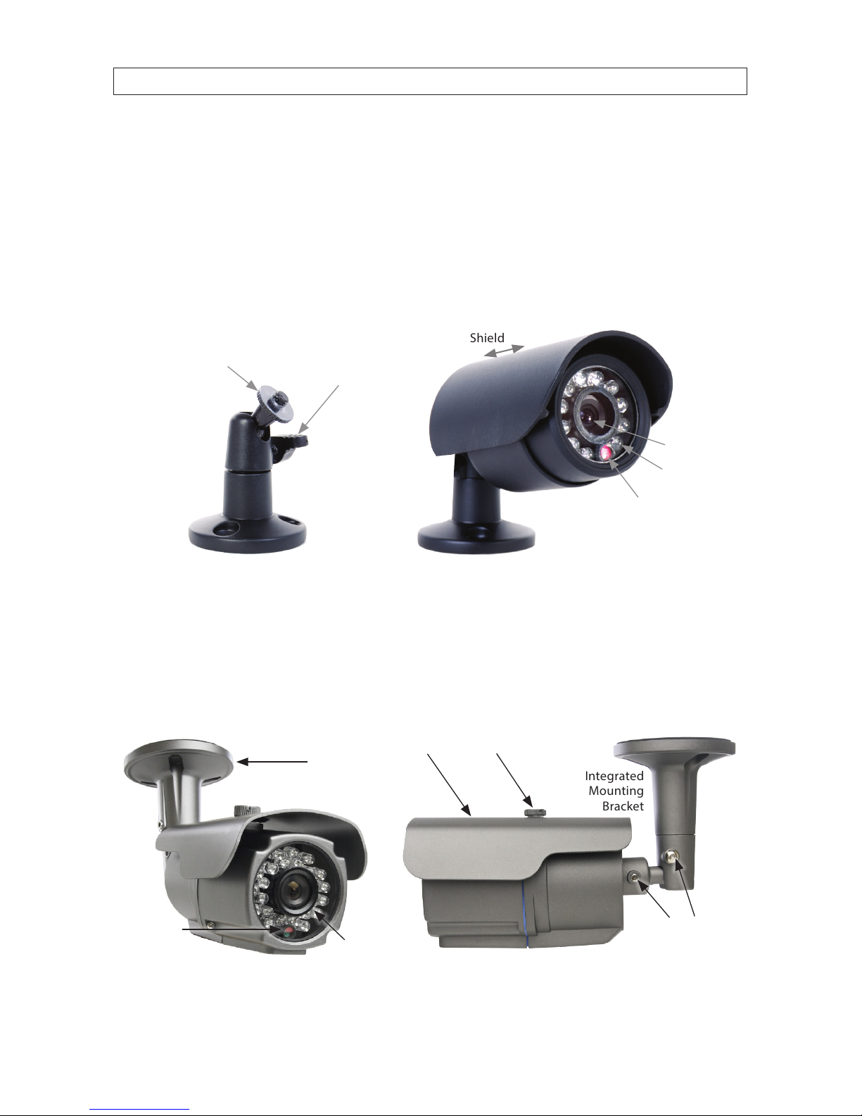
1.2 Cameras
Four CFC6044IR cameras are included with each ECO4IR, ECO4LCD and ECO4IRPROMO system. The ECO4IR2 and ECO4LCD2 systems
each include four BC600 cameras.
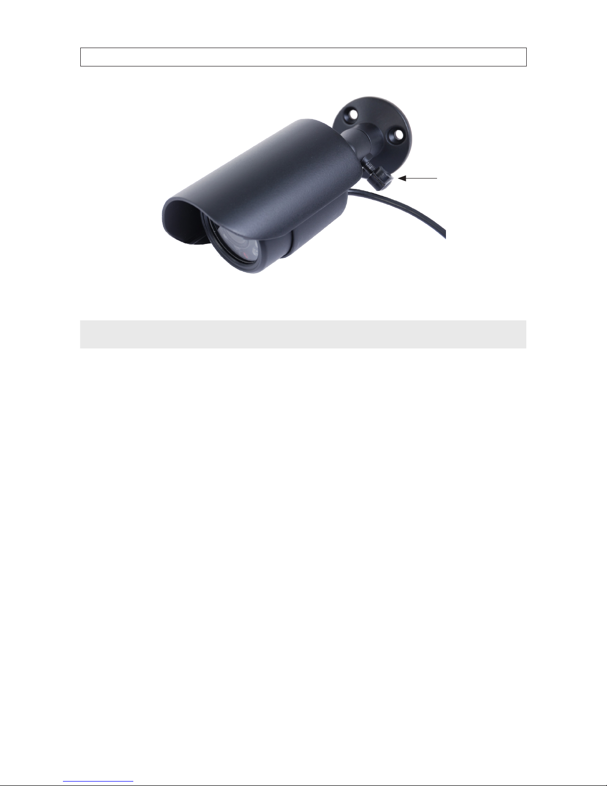
CFC6044IR cameras
The CFC6044IR cameras have no controls and indicators, but do include installation features.
Adjustable
Sun Shield
Lens
Mounting
Bracket
Assembly
Camera Assembly
with Mounting Bracket
IR Array
Light Level
Sensor
Directional
Adjustment Set
Screw
Camera Mounting
Thumb Screw
CFC6044IR camera (drop cable not shown)
The camera drop cable includes two connectors, a BNC connector for the video signal, and a power connector.
BC600 cameras
The BC600 cameras have no controls and indicators, but do include installation features.
IR LED Array
CDS Sensor
Base
Integrated
Mounting
Bracket
Sun shield
Mounting Bracket
Adjustment Screws
Hold Down Screw
BC600 camera (drop cable not shown)
The camera drop cable includes two connectors, a BNC connector for the video signal, and a power connector.

6
SECTION 2: INSTALLING YOUR SYSTEM
SECTION 2
Installing the System
2.1 Getting Started: Unpacking the Equipment
Your system includes:
• 4 channel H.264 networkable DVR
• 4 Cameras
• 4 – 60’ video/power extension cables
• Power adapter and 5-way splitter
• Remote control and USB mouse
• Monitor (with ECO4LCD only)
• Quick-start reference guide (this document)
• Resource Pack Mini-CD with user guides for the DVR, cameras, smartphone applications
Remove the equipment from its packaging and place it on a at, clean surface. Inspect each item. If any visible damage is present,
contact your supplier for a replacement. Verify that your order is complete.
What you need
Although each security system installation is dierent, most require the following items not included with your system
components:
• Tools to install the cameras and route power and video cables
• Fasteners to attach the cameras to the mounting surfaces
• A display device and cabling to connect to the DVR (ECO4IR and ECO4IRPROMO systems). The DVR will connect directly to a
VGA video monitor, or to a TV with a BNC to RCA adapter and RCA cable. The display device is usually needed only for system
setup. It can be disconnected when the DVR is networked for access across a LAN or Internet.
• Uninterruptible power supply (UPS). This device is used to ensure system stability during voltage surges, sags, and outages. If a
UPS is not available, a power strip with strong surge protection is highly recommended.
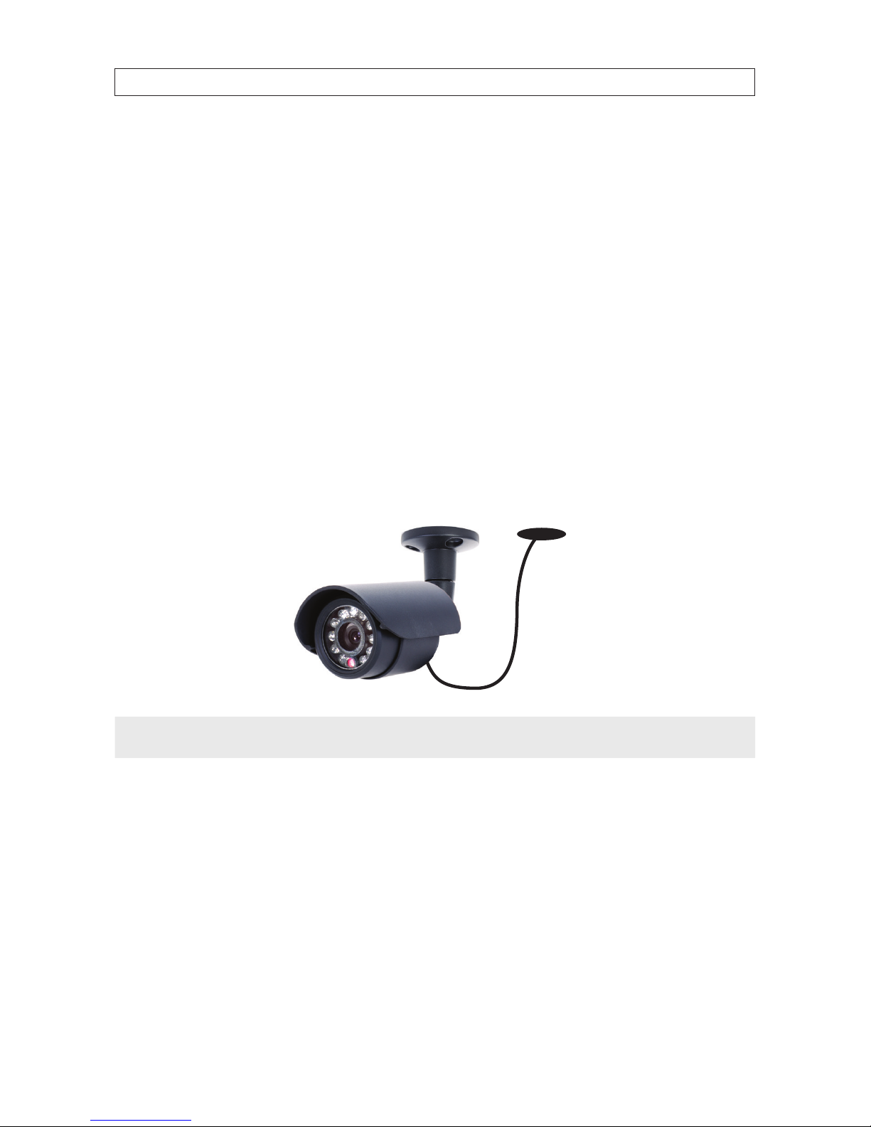
2.2 Camera installation
The CFC6044IR and BC600 cameras are precision instruments that will provide years of quality service when used properly. Included
with each camera is:
• An adjustable mounting bracket that is attached to the back of the camera.
• 60’ video and power extension cable
7
4-Camera H.264 Security System Setup Guide
SECTION 2: INSTALLING YOUR SYSTEM
2.2.1 Camera placement
Plan your camera installation carefully. Identify the locations where cameras will provide the best coverage, considering:
• Field of view – Cameras should be positioned so they can eectively view the entire area that must be monitored, and in a
location where tampering with them is dicult.
• Lighting – Direct light shining on the camera lens or bright reections from shiny objects in the eld of view can diminish
video quality and camera performance. Mount the camera in shaded areas, if possible, or where light on the lens can be
minimized.
• Ease of installation – Must be able to install the camera at the location, considering mounting hardware requirements,
temperature, dust, moisture, etc.
About weatherproof cameras
Weatherproof cameras can be mounted in any open area, such as on a telephone pole or on the side of a building. However, for best
results, we recommend you mount your cameras in a sheltered area, such as under the eave or roof of a building. Point the camera
in the direction you wish to observe. When routing cable near the camera, allow enough slack to form a U-shaped “drip loop” to
help direct moisture or rain water, that accumulates on the cable, away from the camera.
Drip Loop
Drop
Cable
NOTE
Cable connectors are not weatherproof.
Video/power cables can be run almost anywhere, and are frequently routed through attics or above drop/acoustic ceilings because
of the ease of installation. For added security, we recommend you run your cables in areas with limited access to prevent tampering.
Avoid running the cable near high voltage appliances such as uorescent lighting. Electrical noise and magnetic elds produced by
these devices may aect video signal quality.
A 60’ video/power extension cable is shipped with every camera in your system. 100’ and custom-length cables are also available
from your supplier.
8
SECTION 2: INSTALLING YOUR SYSTEM
2.2.2 Mounting
1. Using the camera mounting bracket assembly plate as a template, mark the location for the mounting screws on the mounting
surface.
2. Drill holes into the mounting surface for the mounting screws, wall inserts, or other attachment hardware as needed.
3. If you are routing the video/power drop cable through the mounting surface, drill a ¾" hole near the mounting bracket for the
drop cable.
4. Attach the mounting bracket to the mounting surface using appropriate fasteners.
5. Attach the camera to the mounting bracket.
6. Loosen the directional adjustment screw and point the camera at your surveillance target, then tighten the screw to hold it in
place. (Note: This adjustment may need correction when video from the camera is observed.)
7. Route the camera drop cable through the hole drilled for it in the mounting surface, if used. If the camera is installed where
moisture may accumulate on it, leave a “drip loop” in the cable so that beads of water that collects on the cable ow away
from the camera and the drop cable connectors.
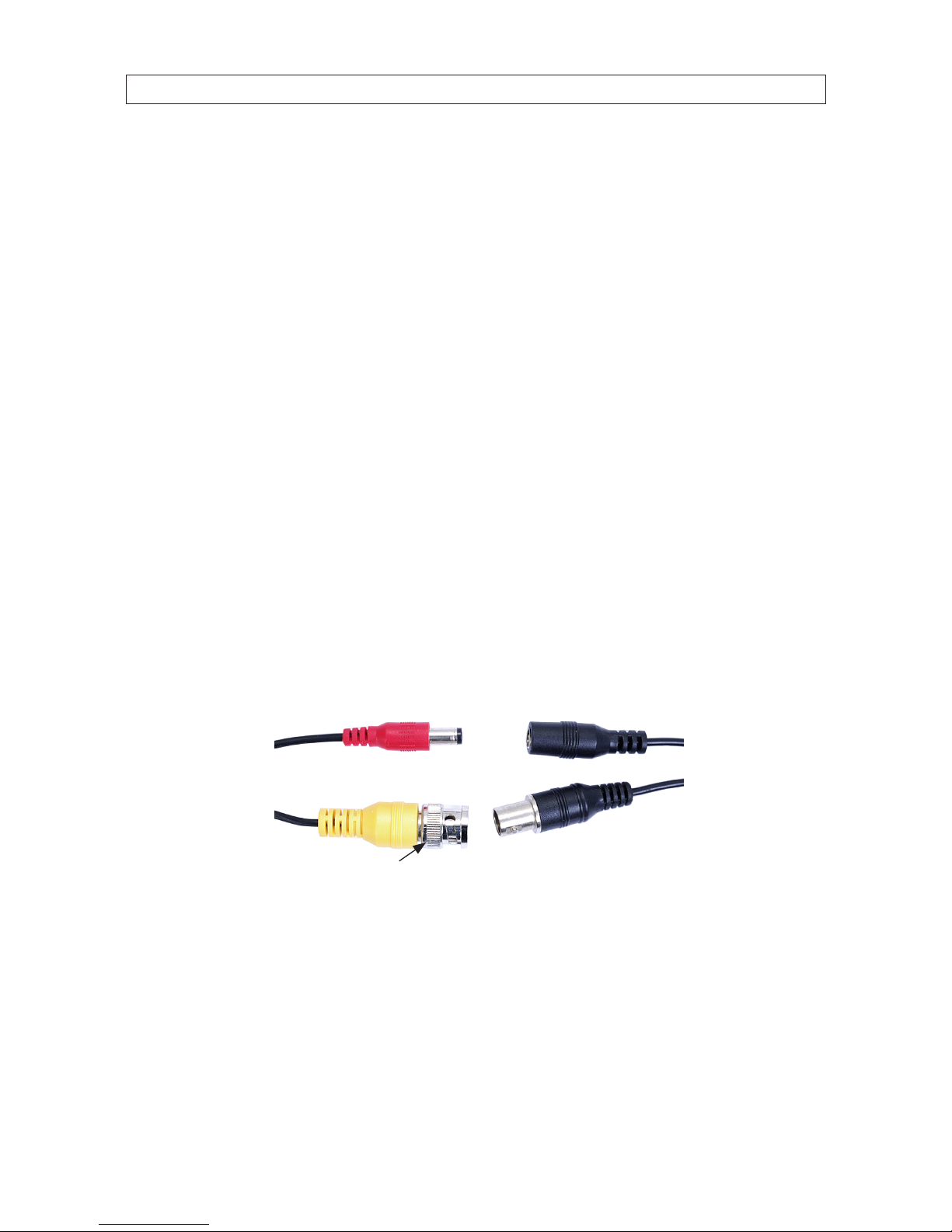
8. Attach a video/power extension cable to the camera drop cable (see diagram below). Note: When connecting the video
cables, fully rotate the lock ring to hold them together.
Extension
Cable
Camera
Drop Cable
Power
Video
Lock Ring
If the connectors might be exposed to moisture or other contaminants, seal them with electrical tape or other material.
9. Route the other end of the video/power extension cable to the DVR backpanel.
10. Repeat this procedure for all the cameras you are installing.
9
4-Camera H.264 Security System Setup Guide
SECTION 2: INSTALLING YOUR SYSTEM
2.3 Install and setup a monitor
1. Install and setup your monitor in accordance with the instructions provided with the monitor. Do not power it on at this time.
2. Cable the DVR Monitor Out (VGA) connector to your monitor’s VGA input. You can also use the monitor out BNC interface, but
the signal quality is better through the VGA interface.
Monitor Out
(BNC)
Monitor Out
(VGA)
NOTE
Some monitors have multiple inputs such including VGA ,HDMI, BNC, etc. If you are using this kind of monitor, congure your
monitor to display the input from your DVR.
2.4 DVR installation
2.4.1 Placement
Your monitoring and recording equipment is central to constant surveillance and the reliable capture of video evidence. We strongly
suggest that it be installed in a secure location with access limited to authorized personnel.
DVRs generate heat and should be placed in a ventilated area. A high temperature environment will reduce the life span and
reliability of the equipment. Additionally, the DVR is not weatherproof, so avoid exposure to liquids and excessive dust. Do not place
objects along the sides or behind the DVR that will block airow through the unit.
Uninterruptible power supplies
It is strongly suggested that power to the system be routed through an uninterruptible power supply (UPS). These devices will keep
your security system running through most power outages, in addition to providing excellent surge and sag protection. The UPS
should support your video recorder and all cameras to ensure normal operation during abnormal power conditions.
10
SECTION 2: INSTALLING YOUR SYSTEM
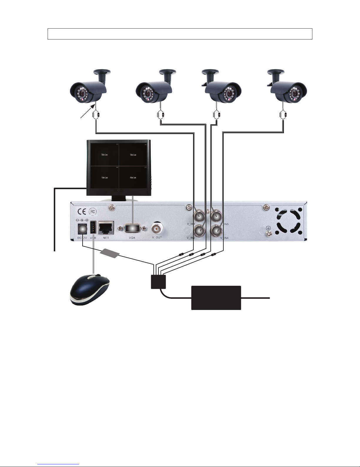
2.5 Connecting the components together
Video/Power
Extension Cables
VGA Cable
5-Way
Power
Splitter
To 120 VAC
Monitor
Power
Power Adapter
Camera
Drop Cable
To UPS/
120 VAC
Typical Interconnection Diagram*
* NOTE: Power cabling shown in the diagram above is recommended for systems with CFC6044IR and BC600 cameras. If you are
not installing these cameras, power requirements for your cameras may be dierent. Refer to the documentation provided with
your camera for specic instructions and recommendations.
1. Connect the system mouse to the USB connector on the DVR back panel.
2. Connect the camera video signal cables (BNC connectors) to the VIDEO IN CH1 to CH4 connectors.
11
4-Camera H.264 Security System Setup Guide
SECTION 2: INSTALLING YOUR SYSTEM
3. Connect a display device to the DVR. If using a VGA monitor for a display, connect it to the VGA MAIN OUT connector. If using
the BNC MAIN OUT connector to drive a display such as a TV, attach the appropriate cables between the BNC MAIN OUT and
your display device.
4. Connect the 5-way power splitter to the power adapter, then:
a. Connect the lead marked DVR POWER to the DC 12V connector on the DVR back panel.
b. Connect the other leads of the splitter to the mating connectors on the video/power extension cables routed to the
cameras.
5. Connect the power cord to the power adapter and plug it into a standard grounded 120 Vac power source through a UPS or
surge protector.
6. Power on your system monitor.
7. Press the power button on the DVR front panel to power on the unit. A startup “Loading” screen will appear on the display.
After a few seconds, the screen will change to the camera view screen.
..
Note: The images you see from your cameras may be dierent from those shown here.
2.6 Adjusting the camera
Adjust your camera to produce the best performance:
• While observing video from your camera, loosen the directional adjustment set screw on the camera mounting assembly, aim
the camera at your surveillance target, then tighten the directional adjustment set screw.
12
SECTION 2: INSTALLING YOUR SYSTEM
Directional
Adjustment
Set Screw
• In brightly lit environments, adjust the sun shield as needed reduce light shining on the lens.
NOTE
If you are installing a dierent camera, refer to the documentation provided to setup the camera.
13
4-Camera H.264 Security System Setup Guide
SECTION 3: SYSTEM SETUP
SECTION 3
System Setup
Setting up your DVR includes logging into your DVR, setting the clock, setting administrator and user account passwords, and
setting up scheduled and/or automated motion recording.
3.1 Login to the DVR
Initially, two access accounts are provided in your system: Admin and user1. With the Admin login, you can make conguration
changes to the system, create user accounts and passwords, and control the privileges allotted to each account. With the factory
default user1 account login you cannot make conguration changes or create accounts, but can change your own password. The
factory default Admin and user1 account passwords are:
Admin: 888888
user1: 666666
To log into the system:
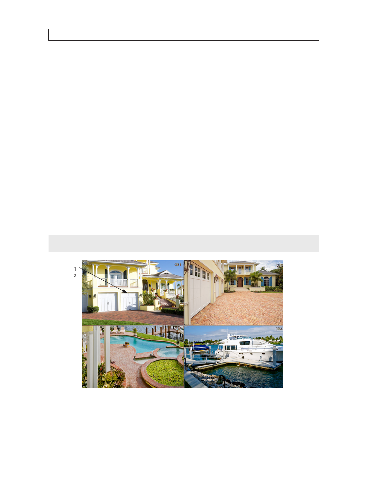
1. Power on the DVR and wait until it advances to the camera view screen. A typical camera view screen is shown below.
NOTE
During initial startup of the system, no password is required.
Image from
Channel 1
Camera
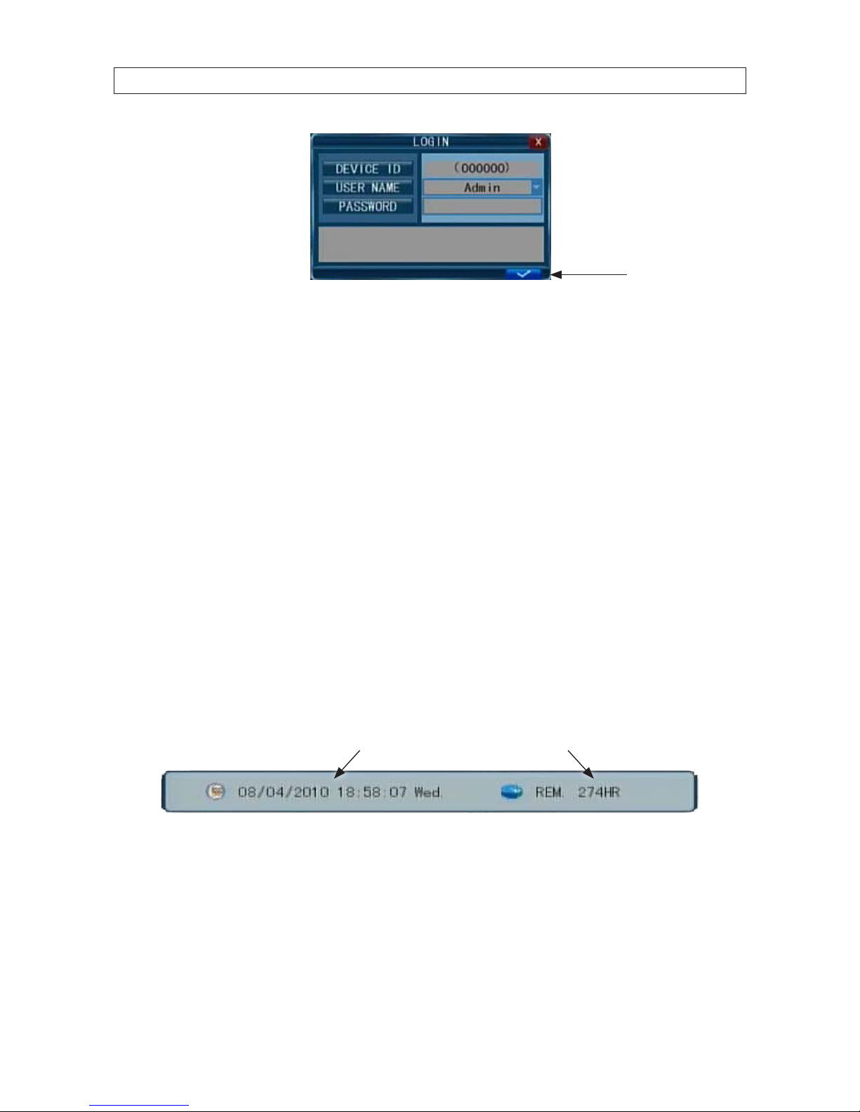
2. Press the MENU button on the front panel twice, or right-click the mouse twice anywhere on the screen. An Input
Password window will appear.
14
SECTION 3: SYSTEM SETUP
Conrm entry
3. Click the q icons to the right of the User Name eld parameter eld and select Admin. To make conguration changes to the
system, you must login to the Admin account.
4. Using the mouse, click the entry eld on the PASSWORD line, then click the number buttons that appear to enter the account
password. For example, to enter the default Admin password, 888888, click the “8” button six times.
5. Click the a (check mark) icon in the lower right corner of the window to conrm your entry and enter the login information.
A tool bar icon strip will appear at the bottom of the screen.
3.2 Conguring the system
Basic system conguration settings include setting the screen language, video system format, system time, creating users,
initializing the hard disk drive (HDD), and setting up automated recording.
1. If the system is not running, power on the DVR and wait until it completes initialization.
2. Right-click anywhere on the desktop, or press the MENU button. A status bar will appear.
3. Compare the DVR system date and time shown on the Status Bar with an accurate clock.
System Date and Time Remaining HDD Recording TIme
Status Bar
Note: To see an accurate clock, access a reliable Internet time server, such as tf.nist.gov
4. Right-click the mouse anywhere on the screen again. The Status bar will change to a Tools Bar or a login window. If a LOGIN
window opens, log in to the system as an Admin (see above).
15
4-Camera H.264 Security System Setup Guide
SECTION 3: SYSTEM SETUP
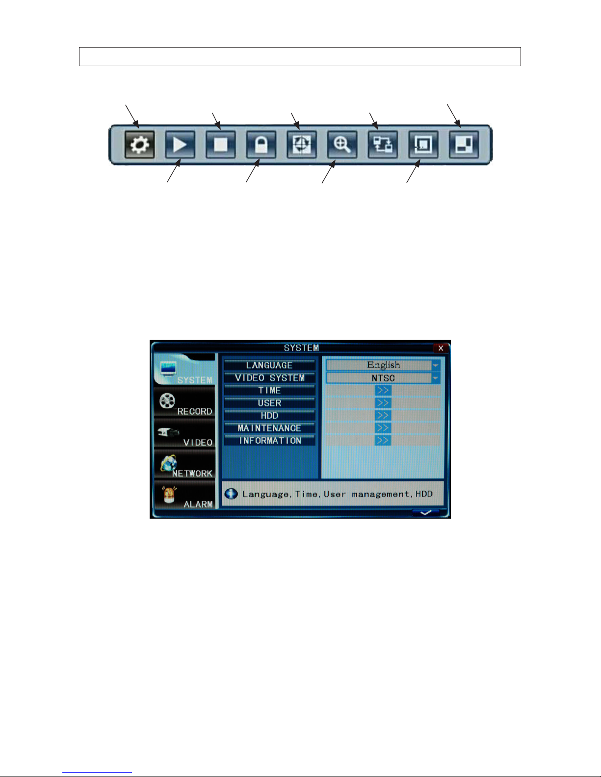
PIP*2
PIP*1
System Settings
EZoomPlay
Manual Record /
Stop Manual Record
VGA / BNC
Switch
Auto
Sequence
Keylock
Tool Bar
5. Click the Settings button on the Tool Bar.
3.2.1 Setting the screen language and video system format
1. In the Settings window SYSTEM tab, click the q icon at the right end of the LANGUAGE line. Select (click) the screen
language you prefer from the dropdown list.
2. If the VIDEO SYSTEM option does not indicate NTSC, click the q icon at the right end of the VIDEO SYSTEM line, then select
NTSC from the dropdown list.
3.2.1 Setting the system time
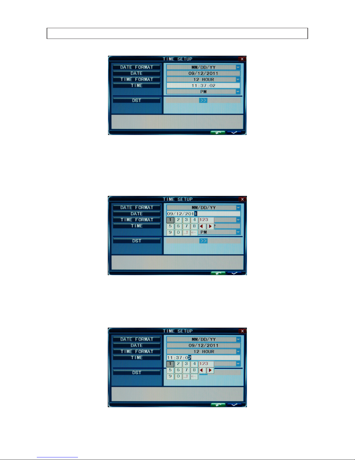
1. On the TIME line, click the >> icon to open the TIME SETUP window.
16
SECTION 3: SYSTEM SETUP
2. Click the q icon at the right end of the DATE FORMAT line. Select the format you prefer: MM/DD/YY, YY-MM-DD, or
DD -MM-YY.
3. Click the entry on the DATE line. Click the t or u icons to highlight a digit of the date, then click the number value of the
digit To complete the entry and close the virtual keyboard, click the = button.
4. Click the q icon at the right end of the TIME FORMAT line. Select the format you prefer: 12 hour or 24 hour.
5. Click the entry on the TIME line. Click the t or u icons to highlight a digit of the current time, then click the number value of
the digit. To complete the entry, click the = button.
17
4-Camera H.264 Security System Setup Guide
SECTION 3: SYSTEM SETUP
6. If you selected a 12 hour time format, click the q icon on the line below the TIME entry, then select either AM or PM.
7. On the DST line, click the >> icon to open the DST (ON/OFF) option window. If you select ON, a DST setup window will open.
Use the method like that detailed above to setup the DST start and end time, then click the conrm entry check (a) in the
lower right corner to conrm your entries.
8. Click the CONFIRM button in the NOTE window.
3.2.2 Change the Admin and user1 passwords
Changing the default Admin and user1 account passwords from their initial (default) value adds security to your system. The
factory default account names and their passwords are:
Admin: 888888
user1: 666666
To change these passwords:
1. With the system powered on, right click twice on the desktop or press the menu button on the front panel twice, then log into
the system as the Admin (if a password login is required).
2. Click the Settings icon on the Tool Bar. The SYSTEM tab window will open.
1. On the USER line, click the >> icon to open the USER MANAGEMENT window.
2. On the CHANGE PASSWORD line, click the >> icon to open the USER MANAGEMENT window.
18
SECTION 3: SYSTEM SETUP
3. Click the q icon at the right end of the USER NAME line. From the dropdown list, select Admin.
4. Click the OLD PASSWORD entry eld, then enter the current Admin password using the virtual keyboard.
5. Enter both the NEW PASSWORD and CONFIRM PASSWORD elds with a dierent password. Passwords cannot be more
than 6 digits in length.
6. Click the conrm icon (a) in the lower right corner of the screen, then click the Conrm button in the Note window.
7. Repeat steps 3, 4, 5, and 6 above to change the user1 password.
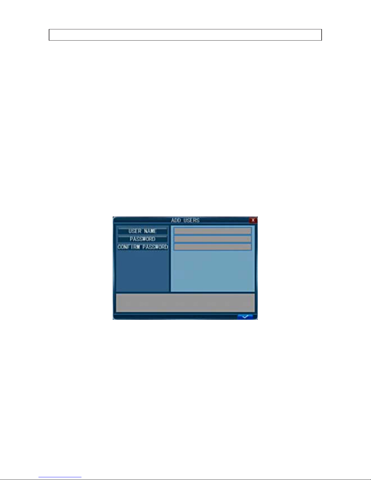
3.2.3 Add uses to the system
1. On the SYSTEM tab USER line, click the >> icon to open the USER MANAGEMENT window.
2. In the USER MANAGEMENT window, click the >> icon on the ADD USER line.
3. Click the entry eld on the USER NAME line to open a virtual keyboard. Click the letters and numbers to enter a username,
then click the = icon to close the keyboard.
4. Enter both the PASSWORD and CONFIRM PASSWORD elds with a password for the user. Passwords cannot be more than
6 digits in length.
5. Click the conrm icon (a) in the lower right corner of the screen, then click the Conrm button in the Note window.
6. Press the MENU button on the front panel or right click on the desktop to return to the USER MANAGEMENT window.
7. In the USER MANAGEMENT window, click the >> icon on the SET PERMISSIONS line.
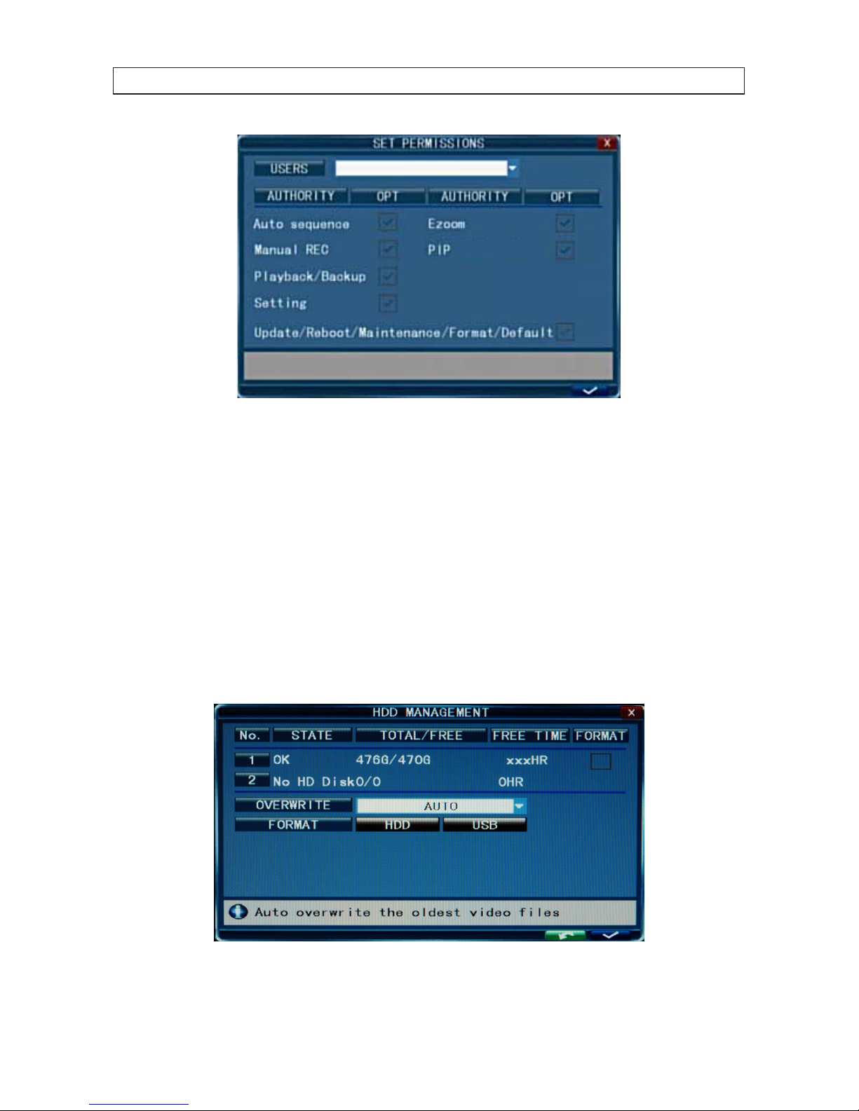
19
4-Camera H.264 Security System Setup Guide
SECTION 3: SYSTEM SETUP
8. Click the q icon at the right end of the USERS line. From the dropdown list, select the name of the user you just created.
9. Click the OPT checkboxes to assign permissions to the new user.
10. Click the conrm icon (a) in the lower right corner of the screen, then click the Conrm button in the Note window.
11. Press the MENU button on the front panel to return to the USER MANAGEMENT window, then press the MENU button again
to return to the SETTINGS window SYSTEM tab.
3.2.4 Set HDD overwrite option
1. On the SYSTEM tab HDD line, click the >> icon to open the HDD MANAGEMENT window.
 Loading...