

High Resolution Indoor/Outdoor
IR Color CCTV Bullet Camera
User Manual
Products: BC600 Series, BC601 Series, BC700 Series Cameras
Please read this manual before using your camera, and always follow the instructions for
safety and proper use. Save this manual for future reference.
BC600-BC601-BC700_CM
11/7/2013
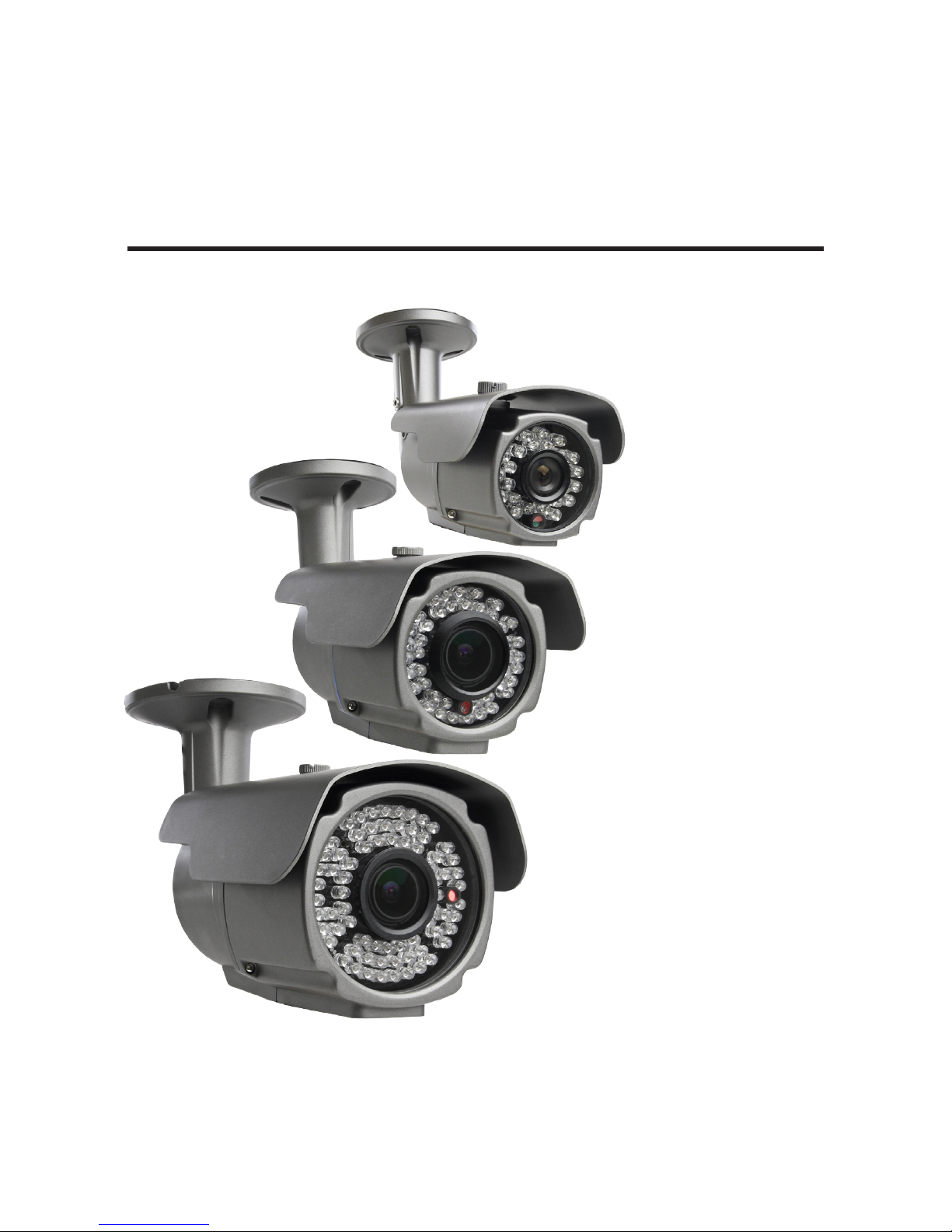
BC600 Camera
BC700VF Camera
BC700VFE Camera

ii
WARNING
!
Changes or modications not expressly approved by the manufacturer could void the user’s authority to operate the camera.
CAUTION
To prevent electric shock and risk of re hazards, do NOT use other than the specied power source.
REGULATORY NOTICE
These cameras comply with Part 15 of the FCC Rules. Operation is subject to the following two conditions:
(1) This device may not cause harmful interference, and
(2) This device must accept any interference received, including interference that may cause undesired operation.
This equipment has been tested and found to comply with the limits for a Class A digital device, pursuant to Part
15 of the FCC Rules. These limits are designed to provide reasonable protection against harmful interference in a
residential installation.
This equipment generates, uses, and can radiate radio frequency energy and, if not installed and use in
accordance with the instructions, may cause harmful interference to radio communications.
Operation of this equipment in a residential area is likely to cause interference, in which case the user will be
required to correct the interference at his own expense.
These cameras are CE and RoHS compliant.
LEGAL NOTICE
Observint Technologies (Observint) products are designed to meet safety and performance standards with the use of
specic Observint authorized accessories. Observint disclaims liability associated with the use of non-Observint
authorized accessories.
The recording, transmission, or broadcast of any person’s voice without their consent or a court order is strictly
prohibited by law.
Observint makes no representations concerning the legality of certain product applications such as the making,
transmission, or recording of video and/or audio signals of others without their knowledge and/or consent. We
encourage you to check and comply with all applicable local, state, and federal laws and regulations before
engaging in any form of surveillance or any transmission of radio frequencies.
Other trademarks and trade names may be used in this document to refer to either the entities claiming the marks
and names or their products. Observint disclaims any proprietary interest in trademarks and trade names other than
its own.
No part of this document may be reproduced or distributed in any form or by any means without the express written
permission of Observint
© 2013 Observint Technologies. All Rights Reserved.
11000 N. Mopac Expressway, Building 300, Austin, TX 78759
For Sales and Support, please contact your distributor.

iii
High Resolution Indoor/Outdoor IR CCTV Bullet Camera User Manual
Table of Contents
SECTION 1 Introduction .......................................................................1
1.1 What’s in the box ....................................................................3
1.2 Tools you need .......................................................................3
SECTION 2 Installation ........................................................................4
2.1 General Guidelines ...................................................................4
2.2 Mounting the camera. . . . . . . . . . . . . . . . . . . . . . . . . . . . . . . . . . . . . . . . . . . . . . . . . . . . . . . . . . . . . . . . .4
2.3 Camera adjustments .................................................................5
2.4 OSD Setup (BC700 series cameras only). . . . . . . . . . . . . . . . . . . . . . . . . . . . . . . . . . . . . . . . . . . . . . . . . .6
SECTION 3 Cleaning ........................................................................... 8
SECTION 4 Specications ......................................................................9
APPENDIX A Troubleshooting ...................................................................11

iv
Precautions
• This camera should be installed by qualied personnel only.
• There are no user serviceable parts inside.
• Do not disassemble this camera other than to make initial adjustments.
• Use a UL approved regulated 12 volt DC power supply.
• Use appropriate low voltage power cable to prevent re or electrical shock.
• Please insure that your installation area can support the weight of the camera.
Handle this camera carefully
• Do not use a strong or abrasive detergent when cleaning the camera.
• Do not install near cooling or heating devices.
• Do not install the camera in extreme temperature conditions. Use the camera in environments where temperature
is within 14°F to 122°F. Use adequate ventilation if a camera is installed where high temperatures may occur.
• Do not install or use the camera in an environment where the humidity is high. Very high humidity levels can
reduce image quality.
• Do not install the camera under unstable lighting conditions. Severe lighting change or icker can cause the camera
to work improperly.
• Do not touch the front lens of the camera. Finger prints, dust and soil on the front glass can cloud the video image and
reduce the eectiveness of the IR array.
• Do not drop the camera or subject it to physical shocks.
• Do not expose the camera to rain or spill liquids on it. If it gets wet, wipe dry immediately. Liquids can contain
minerals that corrode the electronic components.
• Do not expose the camera to radioactivity. If exposed to radioactivity the video sensor may fail.
• Do not disassemble the camera. There are no user-serviceable parts inside it.
• Do not drop the camera or subject them to physical shocks. It can cause malfunctions to occur.
• Never point the camera at a strong light, or exposing it to a spotlight or an object reecting the strong light.
Smear or blooming may occur, and it can damage the CCD.
• Before applying power to the camera, check the power source to ensure that it is within specications.
1
High Resolution Indoor/Outdoor IR CCTV Bullet Camera User Manual
SECTION 1: INTRODUCTION
SECTION 1
Introduction
Features
• High resolution color sensor: 600 TV Lines (BC600, BC601 series), 700 TV Lines (BC700 series)
• OSD control functions (BC700 seriess)
• 12 Vdc power
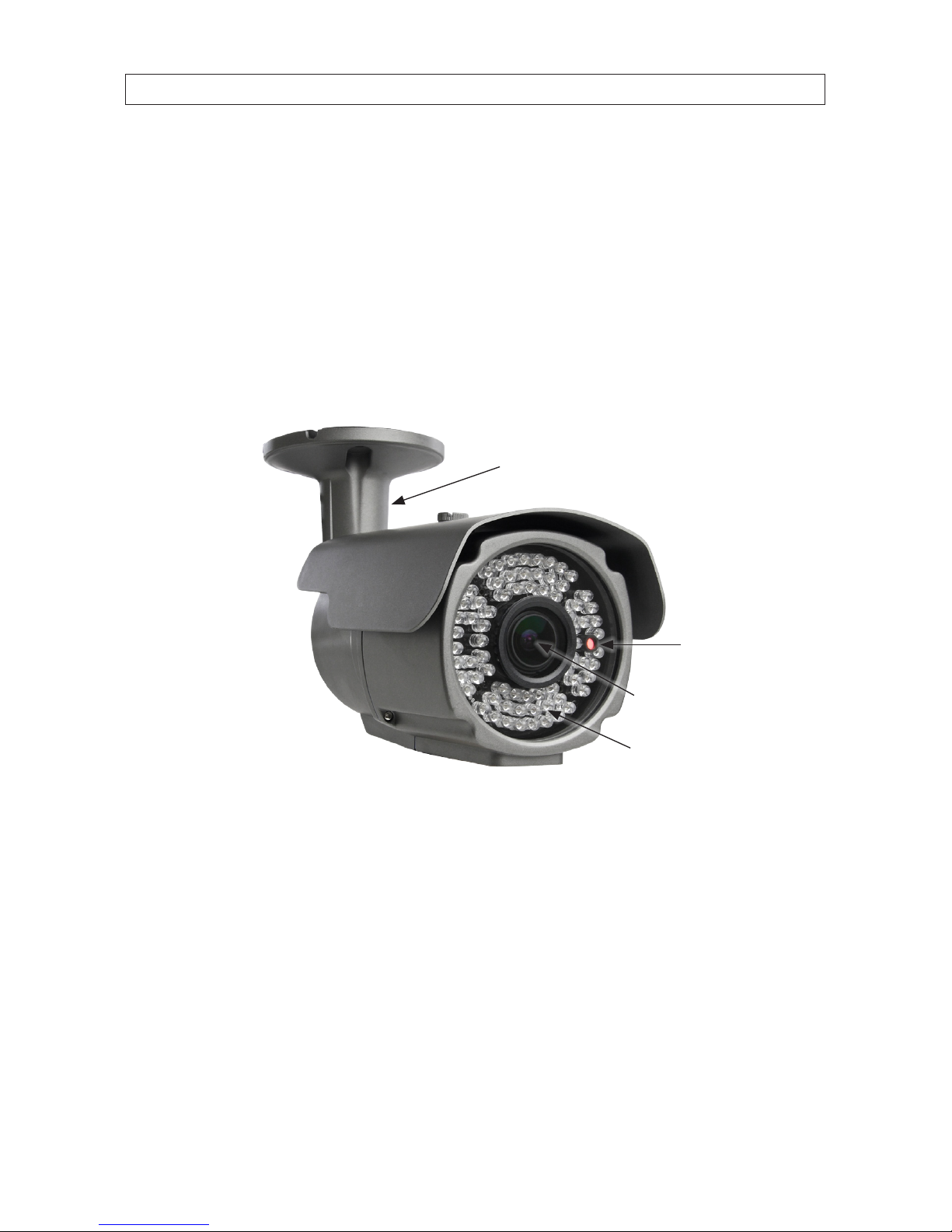
IR LED Array
Integrated
Mounting Bracket
CDS Sensor
Vari-focal Lens
(2.8 mm - 12 mm)
( -VF, -VFE cameras only)
BC700VFE Camera

2
Sun shield
Mounting Bracket
Adjustment Screws
Base
Hold Down Screw
BC600, BC601, BC700 Series Cameras Side View
Cable
Channel
Video Output
Power Input
(12 Vdc)
OSD Controller
(BC700 Series Only)
BC700VF Camera Top View
SECTION 1: INTRODUCTION

3
High Resolution Indoor/Outdoor IR CCTV Bullet Camera User Manual
SECTION 1: INTRODUCTION
Focus, Zoom Adjusters
(vari-focal ( -VF, -VFE) cameras only) Product Label
BC700VFE Camera Bottom
1.1 What’s in the box
Your camera includes the following:
• Camera assembly
• Hex wrench
• Mounting hardware
• This manual
1.2 Tools you need
To install the camera, you will need:
• 12 Vdc power source. See Specications for current requirement.
• Tools and additional fasteners (may be required) for mounting the camera
• Video and power extension cable
• CCTV video setup monitor (optional)

4
SECTION 2: INSTALLATION
SECTION 2
Installation
2.1 General Guidelines
• Camera Lens: Handle the camera carefully to prevent scratching or soiling the lens. If the lens or IR array shield becomes
soiled, clean it only with approved products. See the Cleaning section later in this manual.
• Monitor impedance: Set the monitor impedance switch to 75 .
• Power supply: To avoid re or shock hazard, use only UL listed power supplies.
• Camera drop cable: The camera drop cable includes two connectors:
— Video BNC connector – for transmission of the video signal across a coax (75 ) extension cable.
— Power connector – Use 12 Vac power source (see the Specications section for power requirements). When
applying 12 Vdc power, observe the power polarity. See the picture below for the connector polarity conguration.
Power
Connector
Video BNC
Connector
Camera Drop Cable
2.2 Mounting the camera
The camera can be mounted on any surface with sucient strength to support it. The video/power drop cable from the camera can
be routed either through the cable hole in the center of the base plate, or through a cable guide in the mounting bracket.
1. Using the camera base as a guide, mark the location of the screws that anchor the base plate to the mounting surface. If you
are routing the drop cable through base, also mark the position of the hole for the drop cable.

5
High Resolution Indoor/Outdoor IR CCTV Bullet Camera User Manual
SECTION 2: INSTALLATION
NOTE
Position the base plate so that the cable guide in the mounting bracket is pointing away from any source of water,
dust, and other contaminates.
2. Drill holes for the screws that anchor the base to the mounting surface. The mounting hardware provided is appropriate for
most surfaces. However, depending on the surface materials, more appropriate fasteners may be required.
3. Drill a 3/4" hole for the drop cable, if necessary.
4. Route the drop cable through the hole through the base plate, or through the cable guide in the mounting bracket, then
attach the camera assembly to the surface using the appropriate fasteners.
5. Connect the camera drop cable to video and power extension cables as required.
NOTE
Drop cable connectors are not waterproof.
2.3 Camera adjustments
1. Apply power to the camera.
2. If using a CCTV video system monitor to setup your camera, connect the video output of the camera to your CCTV monitor.
3. Verify that video from the camera can be seen on the monitor.
4. While observing video from the camera, use the hex wrench provided to loosen the two mounting bracket adjustment
screws.
5. Point the camera at the center of your surveillance target, then tighten the bracket adjustment screws.

6
SECTION 2: INSTALLATION
90°
360°
Use for
Direction,
Elevation
Adjustment
Use for
Horizon Line
Adjustment
Sun Shield
Hold Down
Screw
6. Adjust the sun shield (forward or back) to reduce glare, if necessary.
7. If your camera has a varifocal lens ( -VF or -VFE models), use the hex wrench provided to adjust the video zoom and focus.
The adjustment screws are located on the bottom of the camera.
8. If your camera is a BC700 series model, congure your camera using the software menus in the OSD. See OSD Setup in
the following subsection.
2.4 OSD Setup (BC700 series cameras only)
BC700 series cameras include on-screen display (OSD) software for adjusting the
internal camera settings to complement specic environment where it is installed.
These settings are adjusted using the OSD controller attached to the camera drop
cable.
The OSD controller includes a joystick that can be pushed down and rocked UP,
DOWN, left (L) and right (R), or, to open the menu system and navigate the
menus.
To use the OSD controller, press the joy stick in (toward the controller block) to
open the OSD menu. (See the menu chart on the following page.) Rock the joystick
UP or DOWN to highlight a parameter or submenu, then press the joystick in
to select it. Rock the joystick right (R) to highlight an option, UP or DOWN
to identify the option, then press the joystick in to select it. Repeat this method to
navigate the menu system and select options.
Joystick
OSD
Controller

7
High Resolution Indoor/Outdoor IR CCTV Bullet Camera User Manual
SECTION 2: INSTALLATION
OSD MENU OPTIONS
OSD SET
LENS
MANUAL
AUTO
TYPE: DC / VIDEO
MODE: CLOSE / AUTO/OPEN SPEED: 0-255
SHUTTER/ AGC
AUTO
HIGH LUMINANCE MODE: SHUT+AUTO IRIS / AUTO IRIS
BRIGHTNESS: 0-255
LOW LUMINANCE MODE: OFF / AGC
BRIGHTNESS: ×0.25, ×0.5, ×0.75, ×1
MANUAL
MODE: SHUT+AGC
SHUTTER: 1/50, 1/120, 1/250, 1/500, 1/1000, 1/2000, 1/4000, 1/10000 s
AGC: 6, 12, 18, 24, 30, 36, 42, 44.8
WHITE BAL
ATW SPEED / DELAY CNT / ATW FRAME / ENVIRONMENT
PUSH / ANTI CR / PUSH LOCK / USER1 / USER2 / MANUAL
BACK LIGHT OFF / BLC / HLC
PICT ADJUST MIRROR / BRIGHTNESS / CONTRAST / SHARPNESS / HUE / GAIN
ATR
OFF --
ON LUMINANCE /CONTRAST
MOTION DET
OFF --
ON
DETECT SENSE / BLOCK DISP / MONITOR AREA / ARE A SEL / TOP / BOTTOM /
LEFT / RIGHT
PRIVACY
OFF --
ON AREA SEL / TOP / BOTTOM / LEFT / RIGHT / COLOR / TRANSP / MOSAIC
DAY/NIGHT
COLOR --
B/W BURST: OFF / ON
AUTO
BURST: OFF / ON
DELAY CNT / DAY-NIGHT / NIGHT-DAY
NR NR MODE: Y/C, OFF, Y, C
CAMERA ID OFF/ON --
SYNC INT --
LANGUAGE ENGLISH / CHINESE / JAPANESE / ESPANOL / PORTUGUESE / PYCCKNN / FRANCAIS / DEUISCH
CAMER A RESET / BACK / EXIT / SAVE ALL

8
SECTION 3: CLEANING
SECTION 3
Cleaning
Clean the camera dome with an approved glass cleaning solution and a lint free cloth.
• Dust can be removed from the unit by wiping it with a soft damp cloth. To remove stains, gently rub the surface with a soft
cloth moistened with a mild detergent solution, then rinse and dry it with a soft cloth.
• Remove all foreign particles, such as plastic or rubber materials, attached to the camera housing. These may cause damage to
the surface over time.
CAUTION
Do not use benzene, thinner or other chemical products on the camera assembly; these may dissolve the paint and
promote damage of the surfaces. Before using any chemical product, read the accompanying instructions carefully.

9
High Resolution Indoor/Outdoor IR CCTV Bullet Camera User Manual
SECTION 4: SPECIFICATIONS
SECTION 4
Specications
Table 1. Specications for BC600 series, BC601 series cameras
Model BC600 BC6 01 BC601V F BC601VFE
Sensor 1/3" CMOS 1/3" SHARP 1/3" SHARP 1/3" SHARP
Eective Picture
Elements (H x V)
728 (H) x 48 8 (V) 768 (H) x 494 (V) 768 (H) x 494 (V ) 768 (H) ) x 494 (V)
Horizontal Resolution 600 T V Line 600 T V Line 600 T V Line 600 T V Line
Minimum Illumination 0.1 lux / F1.2 0.01 lux / F1.2
0.01 lux F1.2 /
0 lux (with IR LED ON)
0.01 lux F1.2 /
0 lux (with IR LED on)
S/N Ratio More than 46 dB More than 48 dB More than 48 dB More than 48 dB
Scanning System 2:1 interface 2:1 interf ace 2:1 inter face 2:1 interface
Synchronous System Internal, negative sync. Internal, negative sync. Internal, negative sync. Internal, negative sync.
Auto Electronic Shutter 1/60 s ~ 1/100,000 s 1/60 s ~ 1/100,000 s 1/60 s ~ 1/100,000 s 1/60 s ~ 1/100,000 s
Gamma Characteristic 0.45 0.45 0.45 0.45
IR Distance
65 ft (wi th Ø5 x 24 PCS
Infrared LEDs)
65 ft (wi th Ø5 x 24 PCS
Infrared LEDs)
131 ft (with Ø5 x 42 PCS
Infrared LEDs)
196 ft (with Ø5 x 72 PCS
Infrared LEDs)
IR Statu s Under 10 lux by CDS Under 10 lux by CDS Under 10 lux by CDS Under 10 lux by CDS
IR Power On CDS AUTO co ntrol CDS AUTO con trol CDS AUTO control CDS AUTO control
Video Output 1 Vp-p, 75 1 Vp-p, 75 1 Vp-p, 75 1 Vp-p, 75
Auto Gain Control Auto Auto Auto Auto
Power/Current 12 Vdc (+/-10%) / 350 mA 12 Vdc (+/-10%) / 350 mA 12 Vdc (+/-10%) / 500 mA 12 Vdc (+/-10%) / 800 mA
Lens 3.6 mm / F2.0 3.6 mm / F2.0 2.8 - 12 mm manual zo om 2.8 - 12 mm manual zoom
Dimensions (w x h x d)
6.89 x 2.72 x 2.17 in
(175 x 69 x 55 mm)
6.89 x 2.72 x 2.17 in
(175 x 69 x 55 mm)
8.66 x 3.15 x 3.15 in
(220 x 80 x 80 mm)
10.24 x 3.86 x 3.74 in
(260 x 98 x 95 mm)
Weight 29.3 oz (830 g) 29.3 oz (830 g) 38.8 oz (1100 g) 49.4 oz (1400 g)
Storage Temperature
-22 ~ 140 °F
(-30 ~ +60 °C)
RH 95 % max
-22 ~ 140 °F
(-30 ~ +60 °C)
RH 95 % max
-22 ~ 140 °F
(-30 ~ +60 °C)
RH 95 % max
-22 ~ 140 °F
(-30 ~ +60 °C)
RH 95 % max
Operating Temperature
14 ~ 122 °F
10 ~ +50 °C
RH 95 % M AX
14 ~ 122 °F
10 ~ +50 °C
RH 95 % max
14 ~ 122 °F
10 ~ +50 °C
RH 95 % max
14 ~ 122 °F
10 ~ +50 °C
RH 95 % max

10
SECTION 4: SPECIFICATIONS
Table 2. Specications for BC700 series cameras
Model BC70 0 BC700V F BC700V FE
Sensor 1/3" Sony Super-HAD CCD II 1/3" Sony Super-HAD CCD II 1/3" Sony Super-HAD CCD II
Eective Picture Elements (H×V)
976 (H) x 494 (V) 976 (H) x 494 (V) 976 (H) x 49 4 (V)
Horizontal Resolution 700 TV Line 700 T V Line 700 T V Line
Minimum Illumination 0.001 lux F1.2 0.001 lux F1.2
0.001 lux F1.2 /
0 lux (with IR LED on)
S/N Ratio More than 52 dB More than 52 dB More than 52 dB
Scanning System 2:1 interface 2:1 interf ace 2:1 inter face
Synchronous System Internal, negative sync. Internal, negative sync. Internal, negative sync.
Auto Electronic Shutter 1/60 s ~ 1/100,000 s 1/60 s ~ 1/100,000 s 1/60 s ~ 1/100,000 s
Gamma Characteristic 0.45 0.45 0.45
IR Distance
65 ft (wi th Ø5 x 24 PCS
Infrared LEDs)
131 ft (with Ø5 x 42 PCS
Infrared LEDs)
196 ft (with Ø5 x 72 PCS
Infrared LEDs)
IR Statu s Under 10 lux by CDS -- Under 10 lux by CDS
IR Power On CDS AUTO co ntrol -- CDS AUTO con trol
Video Output 1 Vp-p, 75 1 Vp-p, 75 1 Vp-p, 75
Auto Gain Control Auto Auto Auto
Power/Current 12 Vdc (+/-10%) / 350 mA 12 Vdc (+/-10%) / 500 mA 12 Vdc (+/-10%) / 800 mA
Lens 3.6mm / F2.0 2.8 - 12 mm manual zoom 2. 8 - 12 mm manual zoom
Dimensions (w x h x d)
6.89 x 2.72 x 2.17 in
(175 x 69 x 55 mm)
8.66 x 3.15 x 3.15 in
(220 x 80 x 80 mm)
10.24 x 3.86 x 3.74 in
(260 x 98 x 95 mm)
Weight 29.3 oz (830 g) 38.8 oz (1100 g) 49.4 oz (1400 g)
Storage Temperature
-22 ~ 140 °F
(-30 ~ +60 °C)
RH 95 % max
-22 ~ 140 °F
(-30 ~ +60 °C)
RH 95 % max
-22 ~ 140 °F
(-30 ~ +60 °C)
RH 95 % max
Operating Temperature
14 ~ 122 °F
10 ~ +50 °C
RH 95 % max
14 ~ 122 °F
10 ~ +50 °C
RH 95 % max
14 ~ 122 °F
10 ~ +50 °C
RH 95 % max

11
High Resolution Indoor/Outdoor IR CCTV Bullet Camera User Manual
APPENDIX A: TROUBLESHOOTING
APPENDIX A
Troubleshooting
Problem Possible Cause
Nothing appears on the screen - Check the power connection.
- Check t he video signal cable connection to the monitor.
The video image is dim or not clear. - If the c amera lens is dir ty, clean it wit h a soft, clean cloth.
- Adjust the monitor controls, if ne cessary.
- If the camera is facing a very strong light, change the camera position.
- Adjust the lens focu s.
The scr een is dark. - Adjust the contras t control of the monitor.
- If you have an intermediate device, set the impedance (75 /Hi-Z) properly, and check the cable
connections.
The camera is not work ing properly and the
surf ace of the camer a is hot.
- Verif y that the camer a is correct ly connecte d to an appropriate regulated p ower source.
The MOTION DETECTION func tion is not work ing - Is “MOTION DETECT ION” mode tur ned on?
- Check t he setting of the MD AREA.
The imag e on the monitor ickers - Make sure that the camera isn’t facing direct s unlight or uore scent light. If necessar y,change the camera
position.
Colors are not quite right. - Check the settings in the WHITE BAL menu.

12
 Loading...