

Page 1
Congratulations and thank you for purchasing OBLO Living Battery Scene Controller. Below you will find useful
operating guidelines.
DEVICE DESCRIPTION
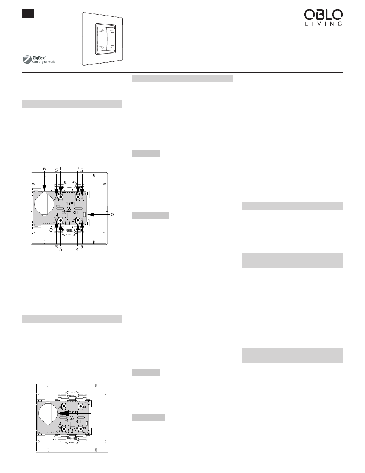
OBLO Living Battery scene controller (Illustration 1) is
wirelessly controlled electronic switch that combines
features of setting up ambiance scenes and temperature
measurement. The device is compliant with ZigBee Home
Automation (ZHA) 1.2 and is guaranteed to function with
any ZHA 1.2-compliant system. In addition, it allows pairing with any device supporting ZHA binding feature.
0 - Main button,
1 - Command button 1, 2 - Command button 2,
3 - Command button 3, 4 - Command button 4,
5 - Led indicators, 6 - Battery housing
Illustration 1
OBLO Living Battery scene controller is battery operated
device (battery type CR2450).
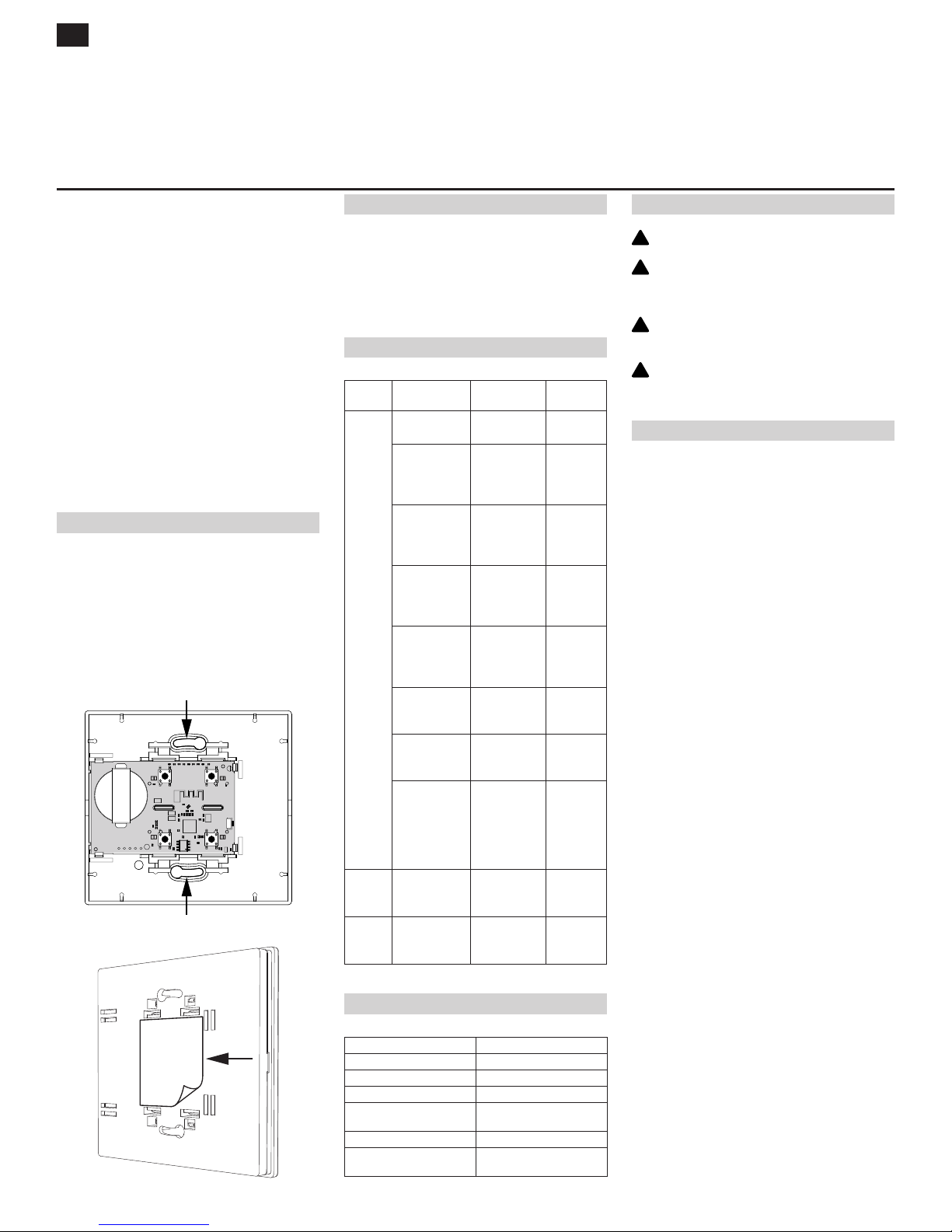
BATTERY ACTIVATION
Battery scene controller has pre-installed battery, which
needs to be activated by gently removing the protective
film from the battery connector.
In case you need to install new battery, gently open device
housing and place the battery as shown in Illustration 2.
NOTE: When inserting battery, make sure the polarity is
correct!
Illustration 2
MODES OF OPERATION
The device supports four modes of operation:
• Normal mode
• Scene setup mode
• Pairing mode
• Key oset mode
NOTE: Scene setup mode, pairing mode and key oset
mode can be active only in cases when Battery scene
controller is a part of standalone network (without home
automation gateway as a central device).
Normal mode
After activation, the device enters normal mode. In this
mode the end user is able to:
• Join Battery scene controller into existing ZigBee
network
• Perform factory reset
• Change mode of operation
Scene setup mode
In this mode, the end user is able to define ambiance
scene by following next steps:
1. Press main button 5 times in order to change mode of
operation from normal to scene setup mode. During
the procedure, all LED indicators will blink green 5
times
2. All devices that will be part of the scene should be
switched to identify mode according to manufacturer’s
instructions. Set desired state on each device (e.g. light
on) for the scene
3. Press one command button on the Battery scene con-
troller in order to assign it to defined scene
4. After successful operation, all LED indicators will blink
red 5 times, which means that device switched back to
normal mode
NOTE: When Battery scene controller is part of home automation gateway’s network, then ambiance scenes can
be defined by using gateway and client application (in accordance with manufacturer’s instructions).
Pairing mode
In this mode, the end user is able to pair Battery scene
controller with other device which supports ZHA binding
feature. This procedure is explained in a separate section
of this document.
Key oset mode
In this mode, the end user is able to change command
button’s and main button’s ID, in order to set up to 10 different scenes for one command button, which means that
one Battery scene controller can support up to 40 dierent scenes.
Command buttons can have 40 dierent ID numbers
(10 per button) and main button can have 10 ID numbers
(from 0 to 9).
To set dierent ID numbers for one command button,
please follow next steps:
1. Press and hold main button for longer than 3 seconds
in order to change mode of operation from normal to
key oset mode. During the procedure, all LED indicators will blink green 3 times
2. To operate with command button ID greater than 4, use
the formula: command button ID = 4 x (main button ID)
+ (1,2,3 or 4), e.g. if we want to operate with command
button ID 13, 14, 15 and 16 instead of 1, 2, 3 and 4 then
our desired main button ID will be 3 (initially main button ID is 0)
3. When key-oset has been set, user can operate with
appropriate com mand button ID numbers until factory
reset is performed
PREPARATION
After activating it for the first time Battery scene controller
is not associated with any ZigBee network. In order to enable proper functioning of the device, it has to be added to
the existing ZHA 1.2-compliant system or paired with any
device supporting ZHA binding feature.
BATTERY SCENE CONTROLLER AS A PART OF
EXISTING ZHA 1.2-COMPLIANT SYSTEM
In order to add Battery scene controller to existing ZHA
1.2-compliant system please follow next steps:
1. On the gateway’s side initiate device inclusion procedure according to gateway manufacturer’s instructions
2. On the Battery scene controller press main button once
to start joining procedure. During joining procedure one
LED will blink red
3. After successful joining, LED will blink green no longer
than 3 minutes
PAIR BATTERY SCENE CONTROLLER WITH
OTHER DEVICE
In order to pair Battery scene controller with other device
supporting ZHA binding feature please follow the procedure below. Since Battery scene controller is initiator
device, the procedure assumes that pairing device has a
role of target device. For additional information about other pairing options please contact our technical support at
support@obloliving.com
1. Create ZigBee network on pairing device according to
manufacturer’s instructions
2. Add Battery scene controller to pairing device’s ZigBee
network:
1) On pairing device start joining procedure according to manufacturer’s instructions
2) On Battery scene controller press main button
once in order to start joining procedure. During the
ENG
OBLO Living
Battery Scene Controller
BC100
BSC-4ST-ZB
OBLO Living LLC
Narodnog Fronta 23a
21000 Novi Sad
Serbia
www.obloliving.com
info@obloliving.com
USER MANUAL
Page 2
procedure, one LED indicator will blink red
3) Upon successful joining there should be LED indication on target device (see manufacturer’s instructions)
3. Pair Battery scene controller as an initiator with the
target device:
1) On Battery scene controller press main button 7
times in order to start pairing procedure. During
operation, all LED indicators will blink green 7 times
2) Switch target device to identify mode according to
manufacturer’s instructions
3) On Battery scene controller choose one command
button and press it in order to pair it with target
device
4) Upon successful pairing the end user is able to
control target device from Battery scene controller. On Battery scene controller all LED indicators
will blink red 7 times, which means that the device
switched back to normal mode
INSTALLATION
Battery scene controller can be placed anywhere in the
room or mounted on the wall with supplied mounting
screws (Illustration 3) or adhesive strips (Illustration 4).
When using adhesive strips, make sure that the surface
is clean.
NOTE: Test the device from desired location before permanently mounting it.
Illustration 3
Illustration 4
FACTORY RESET
In order to restore your Battery scene controller to default factory
settings please follow next steps:
1. Press main button 10 times to reset the device to factory settings
2. After successful operation, all LED indicators will light red
BUTTONS/FUNCTIONS
Mode Button
operation
Action LED
indication
NORMAL
MODE
Main button, 1x
short press
Join ZigBee
network
1x blink red
Main button, 5x
short press
Enter scene
setup mode
All LED
indicators
5x green
blink
Main button, 7x
short press
Enter pairing
mode
All LED
indicators
7x green
blink
Main button, 10x
short press
Factory reset All LED
indicators
red for 3
seconds
Main button
long press (>3
seconds)
Enter key
oset mode
All LED
indicators
3x green
blink
Command
button, 1x short
press
Activate paired
device
1x blink
green
Command
button, 2x short
press
Activate defined scene
1x blink
green
Command button long press
(>1 second)
Send dimming
command (in
case when
paired device
supports
dimming)
1x blink
green
SCENE
SETUP
MODE
Command
button, 1x short
press
Store scene 1x blink red
PAIRING
MODE
Command
button, 1x short
press
Pairing with
other device
1x blink red
TECHNICAL DATA
Communication Protocol ZigBee
Range Up to 15m
Operating Temperature -5 to 45 °C
Protection Degree IP20
Power 1 x CR-2450 battery, pre-in-
stalled
Temperature Measurement -5 to 45 °C; Accuracy: ~1 °C
Dimensions W x H x D:
97.6 x 91.8 x 14 mm
ATTENTION!
WARNING! For indoor use only!
WARNING! Using Battery scene controller in a man-
ner other than outlined in this document is not allowed.
WARNING! When inserting the battery, make sure
that the polarity is correct!
ATTENTION! Always keep batteries away from open
flame and high temperatures. Avoid exposure to direct sunlight!
DECLARATIONS OF CONFORMITY
Hereby, OBLO Living LLC declares that Battery scene
controller is in compliance with the essential requirements
and other relevant provisions of following European directives:
• Council Directive LVD (2014/35/EU)
• Council Directive EMC (2014/30/EU)
• Council Directive RED (2014/53/EU)
• Council Directive ROHS (2002/95/CE)
!
!
!
!
USER MANUAL
ENG
 Loading...