

ELEMENTS:
MODEL SPECIFICATIONS
1. TECHNICAL DATA 2
2. PRE-INSTALLATION 3
3. INSTALLATION 5
4. OPERATION 13
5. TESTING 14
Keep for future use
PAGE 2
OBLICA | ELEMENTS INSTALLATION AND USER MANUAL
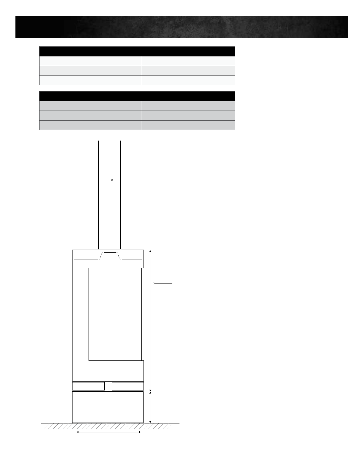
1. TECHNICAL DATA
DETERMINED UNDER TEST CONDITIONS:
Nominal thermal output 7kW
Efficiency (Australian Test) 69%
Emissions (Australian Test) 0.6 g/Kg
8” Flue
400mm
806mm
203mm
MINIMAL
CONFIGURATION
WEIGHT AND DIMENSIONS:
Dimensions Firebox W400 x H806 x D400mm
Firebox weight 130kg
Flue kit Standard 6”/8”/10”

PAGE 3
OBLICA | ELEMENTS INSTALLATION AND USER MANUAL
2. PRE-INSTALLATION
Congratulations on your purchase of the Elements. This appliance should be installed and checked by a qualified
professional. Ensure you have read the operation guidelines thoroughly prior to first use. For any questions or concerns
please contact Oblica on 03 9416 0400.
The installation process is outlined below:
– Determine position of firebox and flue carefully observing the clearances described within this section
– Install the external flue
– Install the internal flue and engage the firebox
– Ensure the floor has adequate protection
CAUTION:
Using components or parts other than those provided by the manufacturer or modifying the specification of components
may result in inferior or unsafe operation. If such action is necessary, consult the manufacturer in the first instance.
WARNING:
• The appliance and flue-system must be installed in accordance with AS/NZS 2918 and the
relevant building code or codes.
• Any modification of the appliance that has not been approved in writing by the testing authority
will be in breach of the approval granted for compliance with AS/NZS 4013.
• Once the flue has been installed and approved by a professional installer, the flue must not be
modified in any way.
PAGE 4
OBLICA | ELEMENTS INSTALLATION AND USER MANUAL
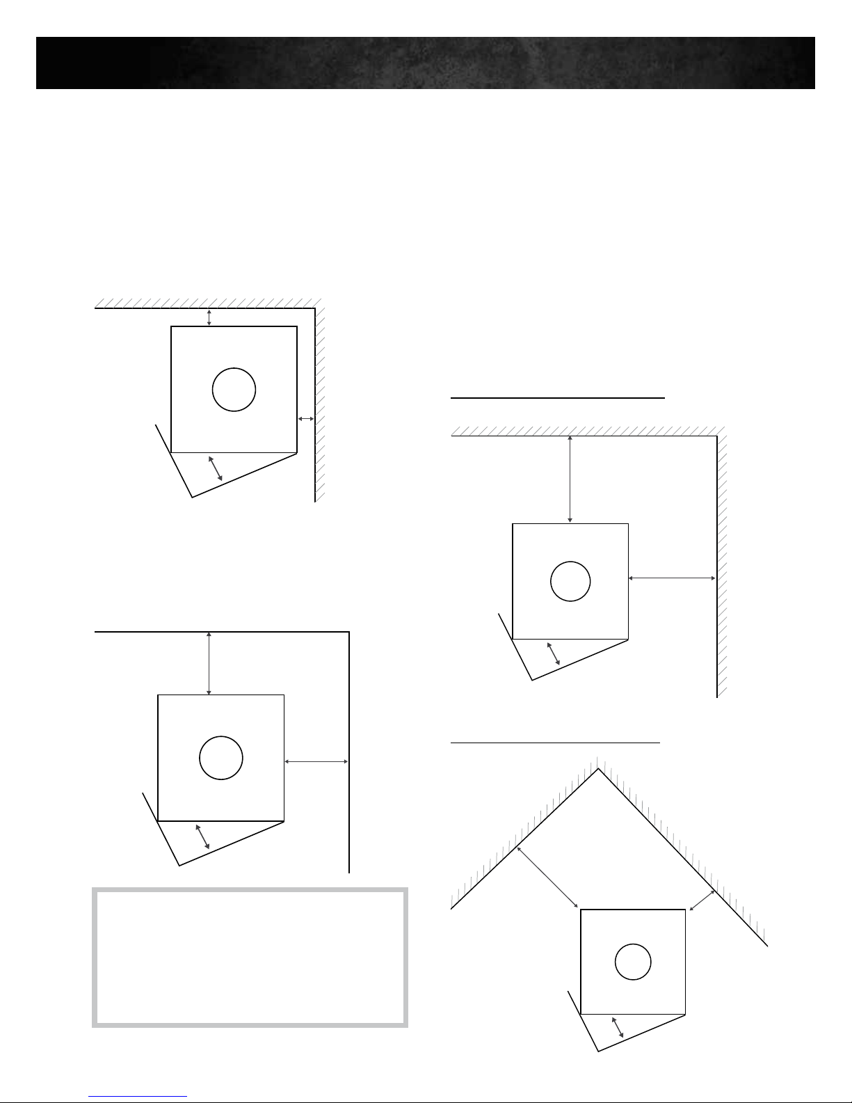
MINIMUM CLEARANCE – INTERNAL
2.1 Clearance from non-combustible surfaces
(eg masonry)
50mm minimum clearance is required from fully
non-combustible surfaces.
50mm
50mm
Non Combustible
Non Combustible
Combustible
Combustible
300mm
300mm
2.2 Clearance from glass
200mm minimum clearance is required from normal
non-combustible glass.
2.3 Clearance from combustible surfaces
(eg timber studs & plasterboard)
Clearances may be reduced with the application of
heat shielding to walls in accordance to the
Australian Building Code.
For information on heat shielding please contact our
office on 03 9416 0400 or email info@oblica.com.au.
IMPORTANT:
Frames must also be considered. Timber window
frames must be treated as combustible surfaces
(see 2.3). Aluminium frames can be treated as
non-combustible surfaces (see 2.2).
2. PRE-INSTALLATION (CONTINUED)
50mm
50mm
Non Combustible
Non Combustible
Glass (frameless or aluminium frame)
Glass (frameless or aluminium frame)
200mm
200mm
Combustible
Combustible
625mm
300mm
300mm
240mm
Combustible
Combustible
Combustible
Combustible
300mm
300mm
Combustible
Combustible
625mm
300mm
300mm
240mm
Combustible
Combustible
Configuration 1 – Parallel installation
Configuration 2 – Corner installation

PAGE 5
OBLICA | ELEMENTS INSTALLATION AND USER MANUAL
3. INSTALLATION
Installation:
Installation must be conducted by a certified fireplace installer.
Installation of chimney stove:
Make sure that the floor‘s carrying capacity is sufficiently high. In case of inadequate carrying capacity, suitable
adjusting measures (e.g. plate for load distribution) are to be taken.
Cleaning:
Make sure to clean your chimney stove at regular intervals. This also applies to emptying the ash box and cleaning
the shaking grate. Also make sure to clean the connection pieces and flues at least once a year and to apply a heat
resistant copper paste on all moving parts such as hinges at least once a year, too. Use a damp cloth and clear
water to clean window glasses. Contact your local chimney sweeper for professional cleaning of your chimney at
regular intervals.
Ventilation of room and chimney stove:
Please ensure sufficient ventilation of the room. Never close air supply openings or convection shafts of the stove.
The fire chamber door of a stove operating independently of ambient air always has to be kept closed
as otherwise, the operation independent of ambient air cannot be guaranteed!
Combustion air: In order to ensure a proper operation, sufficient air flow for the combustion has to be
guaranteed. This chimney stove is constructed to operate independently of ambient air and can either be
connected directly outwards with a combustion air conduit (type: FC41x) or to the air channel of an air exhaust
chimney– LAS- (type: FC51x). The pressure loss of the combustion air conduit may not be higher than 3 Pa.
When using a flexible aluminium tube, please ensure that the pipe is protected against mechanical damages.
The combustion air should be lockable outwards with an air damper and the position of the air damper should be
visible in the installation room. Combustion air conduit as well as the connection piece need to be airtight.
INTRODUCTION
 Loading...