

OBL MB.31, MB.37, MB.50, MB.35, MB.49 Operating Manual
...
SERIE
MB
MC
>
OPERATING MANUAL
JOB N°
PUMP TYPE
SHEET
ELECTRIC ACTUATOR TYPE
OVERALL DRAWING
16
MB/MC 16
MB/MC Z-Z9 17
MECHANISM SECTIONAL DRAWINGS
18
PUMPHEAD SECTIONAL DRAWING
18
ENCLOSED
ITEM
SERIAL/No
GB
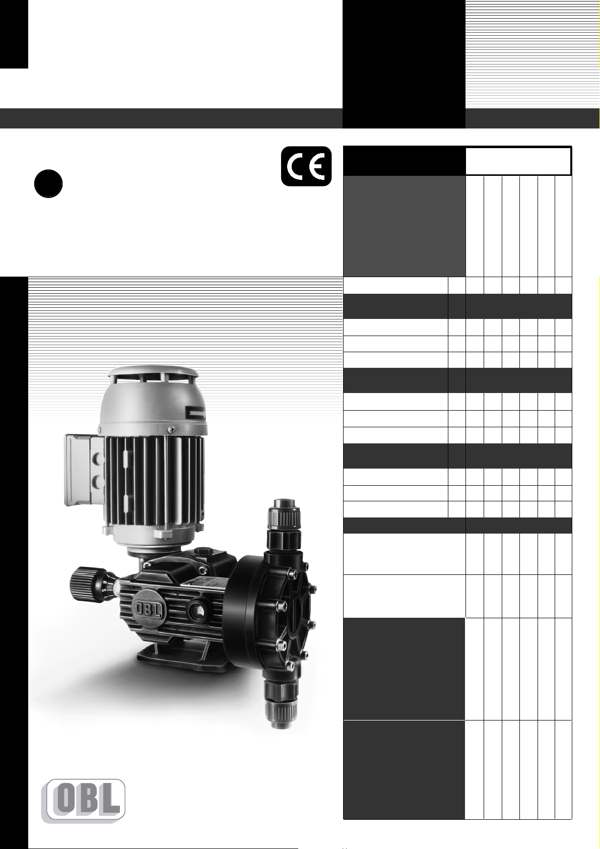
SERIES
MECHANICAL DIAPHRAGM
METERING PUMPS
SPRING RETURN
ENGLISH
:: M_
MB/MC
_GB_12.04 ::
1
2
3
4
5
6
PUMP CLEANING 1
TECHNICAL CHARACTERISTICS 2
MODEL NUMBER 3
1.1 - DESCRIPTION OF THE PUMP 4
1.2 - FLOW RATE 4
1.3 - MANUAL ADJUSTMENT 5
1.4 - MOTOR CHARACTERISTICS 5
1.5 - DIAPHRAGM STRUCTURE 5
2.1 - CORRECT INSTALLATION OF THE PUMP
6
2.2 - SUCTION LINE 6
2.3 - SUCTION SIDE FILTER 7
2.4 - SUCTION PIPING FOR VISCOUS LIQUIDS 8
2.5 - DISCHARGE LINE 8
2.6 - RELIEF VALVE 9
2.7 - INSTALLATION OF THE PULSATION DAMPER 9
2.8 - INSTALLATION OF THE PRESSURE GAUGE 10
2.9 - STANDARD PLANT ARRANGEMENT 10
2.10 -CASING OIL FILLING UP 10
3.1 - BEFORE STARTUP 11
3.2 - PUMP STARTUP 11
3.3 - POSSIBLE TROUBLES DURING STARTUP
12
4.1 - ROUTINE MAINTENANCE 13
4.2 - PREVENTIVE MAINTENANCE 14
4.3 - DISMANTLING (AND REASSEMBLY) 14
4.4 - OPERATING TROUBLES 15
5.1 - MB/5.2 -MC OVERALL DRAWINGS 16
5.3 - MB/MC Z-Z9 OVERALL DRAWINGS 17
MB/MC MECHANISM AND PUMPHEAD
SECTIONAL DRAWING 18
GENERAL SAFETY NORMS 20
DECLARATION OF CONFORMITY 21
GENERAL CHARACTERISTICS
INSTALLATION
STARTUP
MAINTENANCE
OVERALL DRAWINGS
SECTIONAL DRAWINGS
THE MACHINE DIRECTIVE
DECLARATION OF CONFORMITY
INDEX
1
1
2
4
3
A
B
SUCTION SIDE
Please be reminded to collect cleaning water in
specific containers. Containers to be collected
by authorised companies for the disposal of
waste waters.
- Pump to be
packed into palletised crate; pump to
be nailed to the
base in the vertical
position.
-
The cleaning procedure must be repeated for at
least 5 minutes.
-
Continue cleaning through
discharge port, maintaining
the connections horizontal.
SUCTION SIDE
-
Flush with water through the pump suction port
(motor opposite side).
-
Operator to be at least 2 metres away from pump.
-
Place the pump on
the floor, in a suitable area for waste
water collection,
with the inlet and
outlet ports horizontal.
A - Close terminal box cover and seal cable entry with PG plugs.
B- If there are no PG plugs available, the terminal box must be sealed
with adhesive waterproof tape.
-Sostituire il “TAPPO CON FORO” con il “TAPPO CIECO” fornito in dotazione con la pompa.
Pumps to be sent with cleanness certificate, so free from
any chemical trace into liquid end and all wetted parts.
If not supplied, pump (s) will be rejected and
sent back at customer’s charges.
MANDATORY REQUIREMENT
Basic suggestion for pump cleaning
C A U T I O N !
OBL s.r.l. welcome pumps despatched to our premises for servicing.
INFORMATION FOR CUSTOMERS
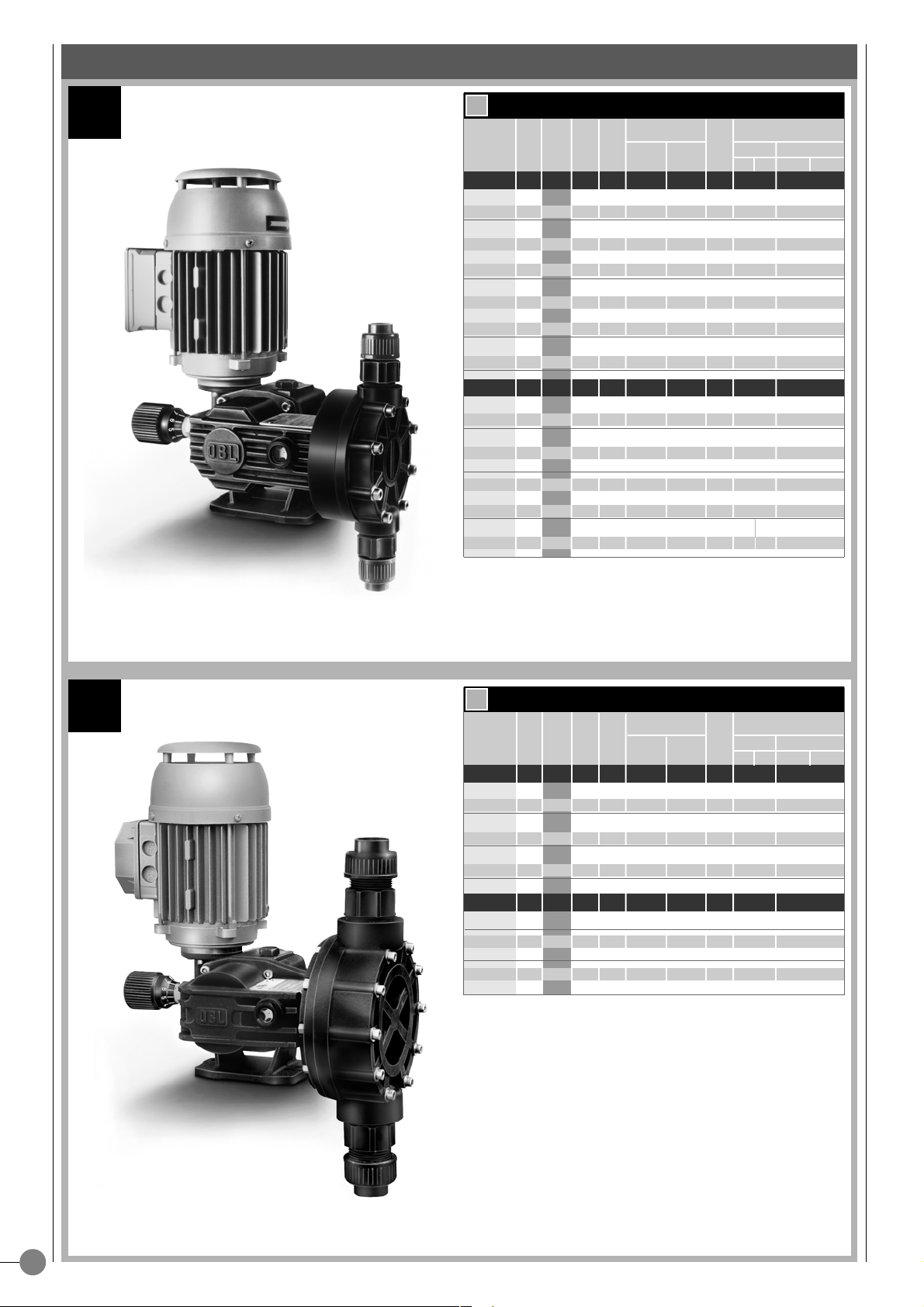
2
MB
MC
50 Hz
50 Hz
60 Hz
60 Hz
➜
➜
TYPE
STROKES/1’
MAX FLOW
RATE l/hØDIAPHRAGM
STROKE
MAX PRESS.
BAR
TYPE
STROKES/1’
MAX FLOW
RATE l/hØDIAPHRAGM
STROKE
MAX PRESS.
BAR
CONNECTIONS
THREADED FLANGED
PP A PP A
VA LV E
A P
TECHNICAL DATA
TECHNICAL DATA
CONNECTIONS
THREADED FLANGED
PP A PP A
VA LV E
A P
MECHANICAL DIAPHRAGM METERING PUMPS
MB.11 36 11 94 2 CML 5 VP 7 12
3/8” BSPF
DN15
1/2”ANSI 150#RF
MB.16 50 16 94 2 CML 5 VP 7 12
3/8” BSPF
DN15
1/2”ANSI 150#RF
MB.23 70 23 94 2 CM 7 VP 7 12
3/8” BSPF
DN15
1/2”ANSI 150#RF
MB.31 95 31 94 2 CM 7 VP 7 8
3/8” BSPF
DN15
1/2”ANSI 150#RF
MB.37 115 37 94 2 CM 7 VP 7 8
3/8” BSPF
DN15
1/2”ANSI 150#RF
MB.50 155 50 94 2 CM 7 VP 7 8
3/8” BSPF
DN15
1/2”ANSI 150#RF
MB.35 36 35 108 4 CM 8
VP 8,5
6
3/8” BSPF
DN15
1/2”ANSI 150#RF
MB.49 50 49 108 4 CM 8
VP 8,5
6
3/8” BSPF
DN15
1/2”ANSI 150#RF
MB.75 70 75 108 4 CM 8
VP 8,5
6
3/8” BSPF
DN15
1/2”ANSI 150#RF
MB.101 95 101 108 4 CM 8
VP 8,5
6
3/8” BSPF
DN15
1/2”ANSI 150#RF
MB.120 115 120 108 4 CM 9
VP 8,5
6
3/8” BSPF
DN15
1/2”ANSI 150#RF
MB.155 155 155 108 4 CM 9
VP 8,5
6
3/8” BSPF
DN15
1/2”ANSI 150#RF
MB.9 30 9 94 2 CML 5 VP 7 12
3/8” BSPF
DN15
1/2”ANSI 150#RF
MB.14 43 14 94 2 CML 5 VP 7 12
3/8” BSPF
DN15
1/2”ANSI 150#RF
MB.28 84 28 94 2 CM 7 VP 7 12
3/8” BSPF
DN15
1/2”ANSI 150#RF
MB.36 114 36 94 2 CM 7 VP 7 8
3/8” BSPF
DN15
1/2”ANSI 150#RF
MB.45 138 45 94 2 CM 7 VP 7 8
3/8” BSPF
DN15
1/2”ANSI 150#RF
MB.42 43 42 108 4 CM 8
VP 8,5
6
3/8” BSPF
DN15
1/2”ANSI 150#RF
MB.58 60 58 108 4 CM 8
VP 8,5
6
3/8” BSPF
DN15
1/2”ANSI 150#RF
MB.90 84 90 108 4 CM 8
VP 8,5
6
3/8” BSPF
DN15
1/2”ANSI 150#RF
MB.121 115 121 108 4 CM 9
VP 8,5
6
3/8” 1/2”
DN15
1/2”ANSI 150#RF
MB.145 138 145 108 4 CM 9
VP 8,5
6
3/8” 1/2”
DN15
1/2”ANSI 150#RF
MC.101 36 100 138 6
CM 13,5 VP 11 G73/4” BSPF
DN20
3/4”ANSI 150#RF
MC.131 50 132 138 6
CM 13,5 VP 11 G73/4” BSPF
DN20
3/4”ANSI 150#RF
MC.201 70 197 138 6
CM 13,5 VP 13,573/4” BSPF
DN20
3/4”ANSI 150#RF
MC.261 95 260 138 6
CM 13,5 VP 13,573/4” BSPF
DN20
3/4”ANSI 150#RF
MC.321 115 320 138 6
VM 16,5 VP 17
5
1”
BSPF
DN25
3/4”ANSI 150#RF
MC.421 155 420 138 6
VM 16,5 VP 17
5
1”
BSPF
DN25
3/4”ANSI 150#RF
MC.120 43 120 138 6
CM 13,5 VP 11 G73/4” BSPF
DN20
3/4”ANSI 150#RF
MC.158 60 158 138 6
CM 13,5 VP 13,573/4” BSPF
DN20
3/4”ANSI 150#RF
MC.236 84 236 138 6
CM 13,5 VP 13,573/4” BSPF
DN20
3/4”ANSI 150#RF
MC.312 114 312 138 6
VM 16,5 VP 17
5
1”
BSPF
DN25
1”ANSI 150#RF
MC.384 138 384 138 6
VM 16,5 VP 17
5
1”
BSPF
DN25
1”ANSI 150#RF
3
MB MC
PP PP11 PP32 A
➜
MB 37 PP F Z
➜
PARTS
MODEL NUMBERMATERIALS OF CONSTRUCTION
KEY TO SYMBOLS
PUPM TYPE
FLOW RATE l/h
PP PP CONSTRUCTION
A AISI-316L CONSTRUCTION
PP11 PP CONSTRUCTION+AISI-316L VALVE AND SEAT
PP32 PP CONSTRUCTION + HASTELLOY C VALVE - INCOLOY 825 SEAT
Z OBL ELECTRIC ACTUATOR
W 3÷15 PSI PNEUMATIC ACTUATOR
F UNI-DIN FLANGED CONNECTIONS
FA ANSI FLANGED CONNECTIONS
LIQUID END PP PP PP AISI 316L
VALVE GUIDE
POLYTHENE/PVC POLYTHENE/PVC POLYTHENE/PVC
AISI 316L
VALVE SEAT PVC AISI 316L
INCOLOY 825
AISI 316L
VA LV E PIREX AISI 316L
HASTELLOY C-276
AISI 316L
VALVE SEAL
VITON (FPM) VITON (FPM) VITON (FPM) VITON (FPM)
VALVE HOUSING PP PP PP AISI 316L
DIAPHRAGM
TEFLON (PTFE) TEFLON (PTFE) TEFLON (PTFE) TEFLON (PTFE)
1.1
1
4
1
0° 180° 360°
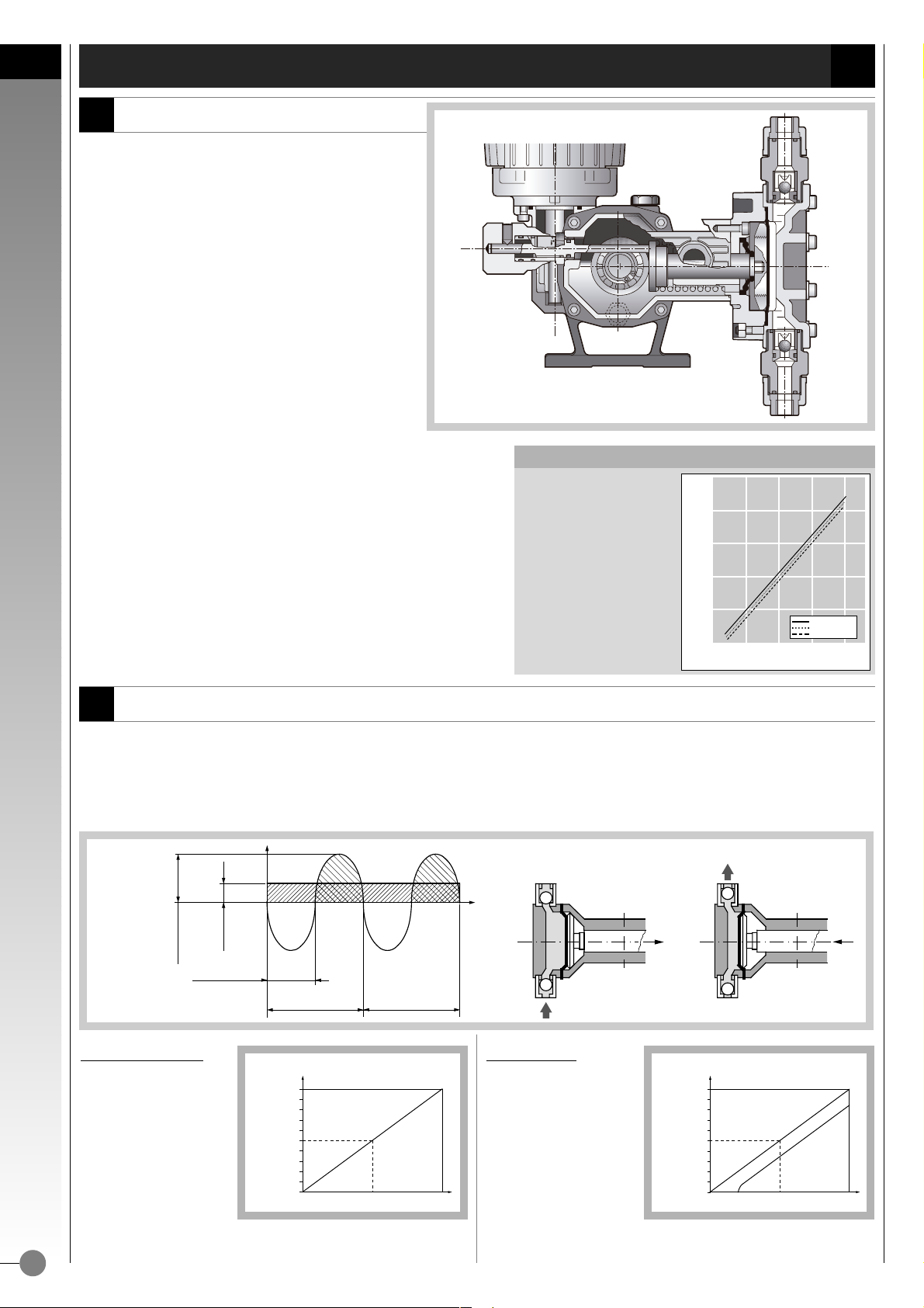
1.2
Fig. 2
Theor
etical flow rate
The theoretical flow rate
corresponds exactly to
the volume displaced by
the diaphragm during
its motion. Its graphic
representation is a diagonal straight line
whose progression is
determined by the
diaphragm stroke increasing (fig.3).
Actual flow rate
The actual flow rate is inevitably less than the theoretical flow rate because of the
losses due to the reaction
time of the valves. The ratio
between these two flow
rates determines the volumetric efficiency of the
pump. The efficiency
depends on pump size, pump head type (plunger or diaphragm), liquid
to be pumped, viscosity of the liquid, working
pressure, etc.
(fig. 4).
0° 50° 100°
10
5
0° 50° 100°
10
5
FLOW RATE
A
C
FLO
W
R
A
TE
TH
.FO
LW
R
A
TE
TH
.FO
LW
R
A
TE
FLOW RATE
CLOSED
OPEN
OPEN
CLOSED
DISCHARGE STAGESUCTION STAGE
2°COMPLETE CYCLE
1° COMPLETE CYCLE
SUCTION
FLOW RATE
PER HOUR
SNAPSHOT
FLOW RATE
• The reciprocating motion of the diaphragm determines the flow thanks to the inlet and outlet check valves of the pump head
(fig. 2).
During the suction stage the inlet valve opens because of the depression created by the diaphragm while the outlet valve remains closed. The product enters the pump head and goes out throught the outlet valve when pushed by the diaphragm during the discharge
stage.
FLOW RATE
THE FLOW RATE LINEARITY
The operating of an OBL mechanical diaphragm reflects the flow
rate linearity of a plunger pump.
This is proved by the graph here
on the left that evidences the
linear proportionality between
flow rate and adjustment percentage.
200
150
100
50
0
25% 50% 75% 100%
Adjustment %
Flow rate l/h
Table A
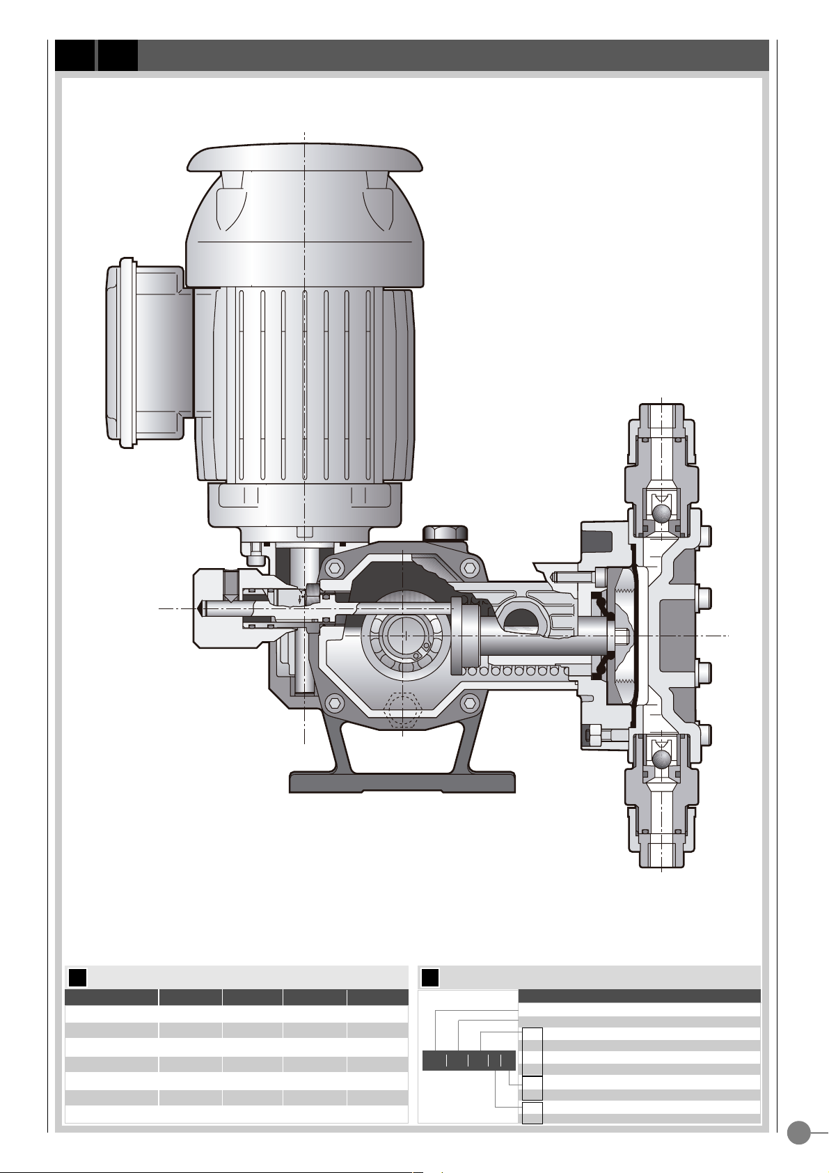
• The OBL’s metering pumps “MB/MC” series are con-
trolled-volume reciprocating pumps.
The crank gear is driven by an electric motor and the
strokes per minute of the diaphragm are given by an
integral, oil-splash-lubricated , endless
screw/wormwheel reduction gear (fig.1).
In MB/MC’s mechanical diaphragm metering pumps,
suction stage (diaphragm backward stroke) is by spring
return.
The MB/MC series metering pumps are characterised by
a so called mechanical diaphragm, where the reciprocating movement is transmitted directly by the crank gear.
The mechanical diaphragm works, both giving the swept
volume, acting basically as plunger, and as separator between crank
gear and the handled fluid.
• The MB/MC mechanical diaphragm metering pumps give a double
advantage:
- Leak-free head.
- No plunger packing and related wearing problems.
These results are achieved thanks to the unique structure of the diaphragm (patented), which bears the whole thrust of the handled liquid,
and, like a plunger pump, guarantees a linear flow rate (table A).
DESCRIPTION OF THE PUMP
GENERAL CHARACTERISTICS
GENERAL CHARACTERISTICS
Fig. 1
1
5
1.3
1.4
1.5
STANDARD
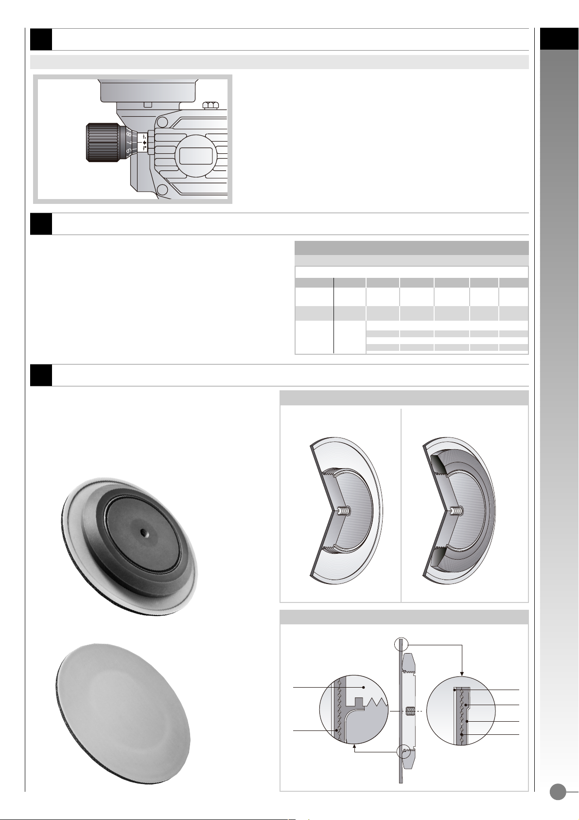
Fig. 5
DETAIL OF THE BONDING BETWEEN DIAPHRAGM AND METALLIC SUPPORT
DIAPHRAGM SECTIONAL VIEW
RUBBER
METALLIC
SUPPORT
PFTE
RUBBER
PFTE
NYLON NET
Sectional view without
plastic support ring.
Complete sectional view with
plastic support ring.
GAMAR MOTOR SPECIAL FLANGE AND SHAFT
PUMP TYPE PHASES kW POLES
SIZE
VOLT Hz
MB THREEPH 0,20 4 63
230
50/60
400
MC THREEPH 0,30 4 63
230
50/60
400
0,24/037 4 63/71 230 50
MB
SINGLEPH
0,24/037 4 63/71 230 60
MC 0,24/037 4 63/71 110 50
0,24/037 4 63/71 110 60
Table B
• The OBL's unique (patented) mechanical diaphragm
design ensures controlled volumetric displacement, giving
plunger-like performances.
Thus the flow rate is virtually unaffected by the working
pressure variations.
DIAPHRAGM STRUCTURE
• In table B are described motors installed on MB/MC pumps.
Endless screw is directly keyed on extended motor shaft.
MOTOR CHARACTERISTICS ACCORDING TO THE PUMP SIZE
• The adjustment of the diaphragm stroke is stepless and regular, and can be
carried out any time, i.e. when the pump stands still or is running (fig.5).
FLOW RATE MANUAL BY MICROMETER
GENERAL CHARACTERISTICS
MANUAL ADJUSTMENT
2
6
2.1
2.2
80 cm. 70 cm.
0÷15 4x6 - - 0÷30 6x10 - 1/4"-
0÷125 -
DN 10
3/8" Ø16
0÷155 -
DN 15
1/2" Ø20
1/2" ANSI
0÷260 -
DN 20
3/4" Ø25
3/4" ANSI
0÷420 -
DN 25
1" Ø32
1" ANSI
➜
➜
2
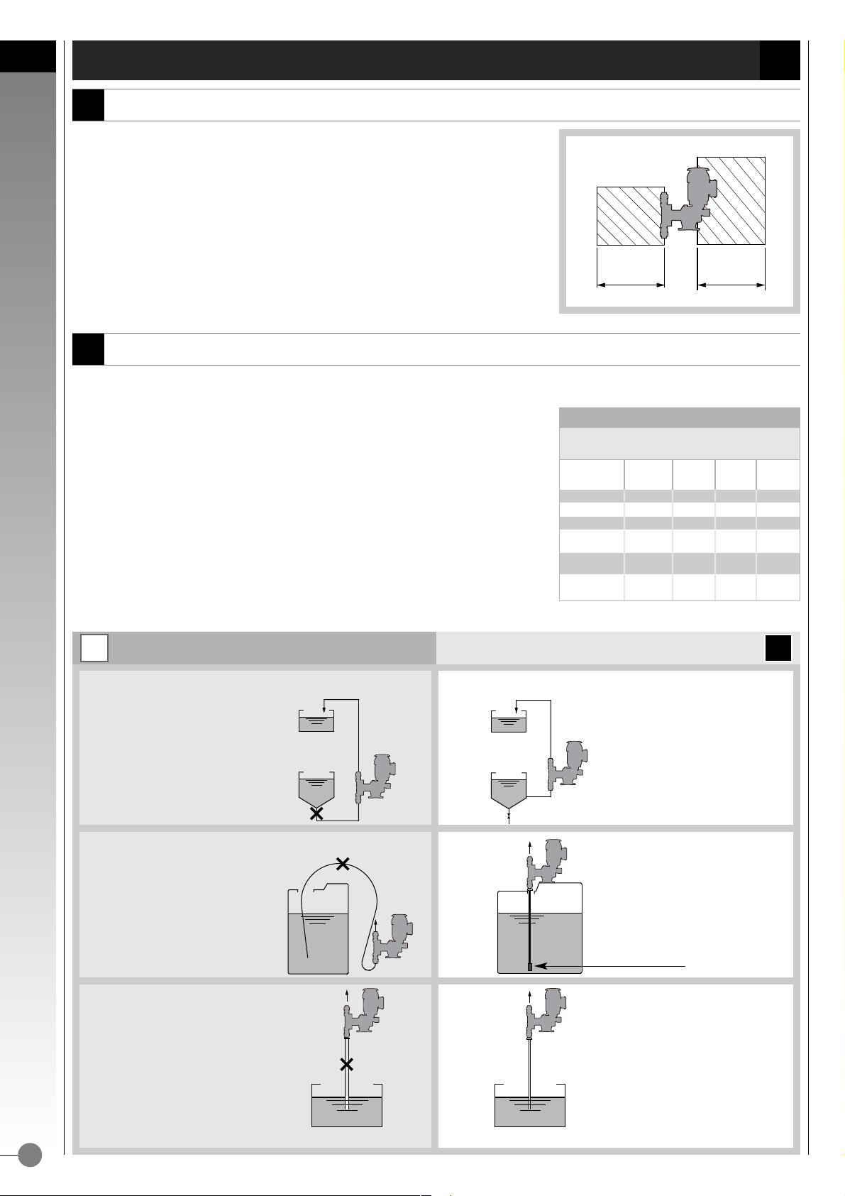
Fig. 7/A
Fig. 6
RIGHTWRONG
FILTER FOOT VALVE
Right
Right
Right
Pipe size according
with table C
Wrong
Risk of clogging of pump valves
Wrong
In the highest point of the piping
the fluid vein breaks
Wrong
Pipe size not according
with table C
• A proper installation and sizing of the suction line are of particular importance for a correct operation of the pump, the following
factors shall be taken into account
:
A) Pipe inner diameter
The pipe internal diameter will be chosen according to the pump flow rate (see table C)
.
The pump connections are oversized, in order to cover all applications.
B) Length of the piping
Suction piping is to be as short as possible, following the indications of table C
it is suggested:
- Max suction lift 1,5 metres
- Total length 2,5 metres (upright plus horizontal)
C) Arrangement of the suction line
For the arrangement of the suction line see Fig. 7/A and 7/B.
Table C
Relationship between flow rate and pipe size
FLOW RATE L/h
PIPE WITH
FITTINGS
FLANGED
PIPE
THREADED
PIPE
PVC GLUED
PIPE
SUCTION LINE
ADJUSTMENT SIDE
HYDRAULIC SIDE
ASSEMBLING AREA
• Provide with adequate clearance areas and safe access for operation and mainte-
nance, in particular in front of the hydraulic side and of the adjustment knob (fig. 6).
• If the pump is installed outdoors, a shelter is recommend, specially when the pump is
equipped with electric actuators or other delicate devices.
• PP pump heads can work properly only at ambient temperature and metered liquid
temperatures below 40°C.
• If necessary, provide suitable protection from sun rays and check the temperature of
the metered liquid.
INSTRUCTIONS FOR A PROPER INSTALLATION
INSTALLATION
INSTALLATION
 Loading...