


OASIS-4i Installation Guide
Warning!
This board contains static sensitive components. Please take the
necessary precautions when handling and installing the board, to
prevent damage or malfunction.
Contents
Introduction...........................................................................................1
Installation Requirements .....................................................................2
Installation Process...............................................................................2
Connector Identification........................................................................3
Hardware Installation Procedure...........................................................3
Driver Installation Procedure for Windows
Driver Installation Procedure for Windows 98/Me................................5
Driver Installation Procedure for Windows NT.....................................6
Configuring the OASIS-4i controller......................................................6
OASIS Configuration Wizard.............................................................6
2000/XP.............................5
OASIS Flash Memory Configuration Utility........................................7
What Next?...........................................................................................9
If You Need Help ..................................................................................9
Troubleshooting Guide..........................................................................9
Introduction
Thank you for purchasing the OASIS-4i four axis stepper controller for
the PCI bus! The OASIS-4i is an advanced, high-performance
controller designed for the most demanding imaging and microscopy
applications. The compact PCI form factor ensures a highly integrated
solution for automation control.
This guide provides an overview of how to physically install the OASIS4i card into your system, install the required driver software, and
configure the controller for your particular setup.

Note that your OASIS-4i may have been provided as part of an
integrated automation system. There may be aspects of your system
configuration that are specialized for your application. In these
situations, please contact your system vendor for details regarding
your configuration before proceeding.
Installation Requirements
In order to install the OASIS-4i card into your system, you will need the
following:
• PC with one three-quarter length PCI slot available
•
Windows® XP, Windows® 2000, Windows® 95/98/Me, or
Windows® NT4.0 operating system
•
CD-ROM drive
One free (hard disk style), power connector, with 2A at 12V
•
available
•
Cross-head screwdriver
•
OASIS-4i Installation CD
Installation Process
The OASIS-4i installation process consists of three distinct steps:
1. Hardware Installation. In this step, you will physically place
the OASIS-4i card inside your computer.
2. Driver Installation. After installing the hardware, you need to
install the driver software so that Windows recognizes the card
and application software can use it.
3. Configuration. You will need to configure the OASIS-4i card to
match your particular system setup.
Once these steps are complete, the OASIS-4i card is generally ready
for use. However, if you are using a 3
need to install additional software so that your application package can
use the OASIS-4i controller to drive the motorized components of your
system. Refer to your application / system documentation for further
details on how to configure the application for use with OASIS-4i.
rd
party application, you may
Connector Identification
–
r
–
r
–
–
A
r
–
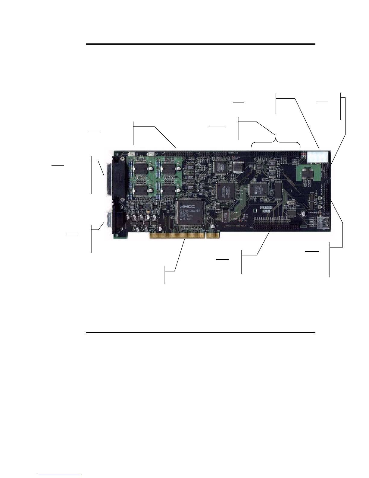
Refer to the following diagram for information regarding the various
connectors available on the OASIS-4i card.
SK1 – XYZ
output, video
I/O, general
logic output
PL1
Trackball
serial port
PL2 – Fourth
axis output
PCI Connecto
SK3,4
Option card
SK2
Option card
PL5 –Motor
powe
PL7
nalogue port
for Joystick o
OI-SNP
PL6
Serial
port
Hardware Installation Procedure
Preparing the
PC case
1) Switch off the PC and unplug from the mains to disable any
standby power.
2) Remove the system unit cover or side panel.
3) Select a suitable PCI slot with no obstructions (preferably one with
adequate air-flow from the auxiliary fan), and remove blanking
panel as necessary.
Figure 1. OASIS-4i Connectors

Fitting the
card
4) Ground yourself to an antistatic mat or other grounded source to
discharge static electricity before handling the board.
5) Pick up the board (still in its anti-static sleeve), by grasping the
metal edge bracket with one hand, and remove the sleeve.
6) Taking care to hold the edges of the board, avoiding contact with
the electronic components, position it over the PCI slot and locate
the tip of the metal bracket in the slot of the PC chassis, before
pushing the board firmly but gently home with a slight rocking
action.
7) Secure the bracket with a retaining screw.
Connecting
power and
options
8a) If intending to use the 4th axis, you will need to fit an adapter
plate to another spare slot and the interconnecting cable to PL2 the
4th axis output. Be careful to attach pin 1 of the ribbon cable (with
the red stripe), to pin 1 of PL2, which is marked on the board
(towards metal bracket).
8b) If fitting a joystick or OI-SNP (Leica SmartMove interface), you will
need to fit an adapter plate to another spare slot and the
interconnection cable to PL7, the Analogue Port. Be careful to
attach pin 1 of the ribbon cable (with the red stripe), to pin 1 of
PL7, which is marked on the board (towards the power connector).
8c) If intending to use the OASIS-XA1 5th axis module, please refer to
the OASIS-XA1 documentation for connection details.
8d) If intending to use the OASIS-DC1 module, please refer to the
OASIS-DC1 documentation for connection details.
9) Connect a spare power connector from the PC power supply to
PL5 at the rear of the board. Preferably the OASIS-4i should be the
only device drawing power from this lead. The on board motor
drive components get their power via the +12V from this connector.
Making
external
connections
10) Replace PC system cover or side panel.
11) If using a Kensington Expert Mouse 5.0 trackball or other serial
control device, connect it to PL1, the 9-pin trackball serial port
below the 44-way main connector.
12) Connect the appropriate cable from SK1, the 44-way XYZ and
video in/out connector, to your desired XY stage, focus adapter(Z)
and video source as required. Notice that this 44 way connector is
keyed to prevent insertion of an incorrect cable.
13) You are now ready to switch on the PC and proceed with the

driver installation for your operating system.
Warning: Do not connect or disconnect motor cables while the PC is
powered on. The OASIS-4i card may be applying power to the motors,
in which case a connection or disconnection could damage the OASIS4i card.
Driver Installation Procedure for Windows
2000/XP
1) Switch on PC and boot into Window.
2) The 'Add New Hardware Wizard' should appear.
3) Select 'Search for best driver for your device' and press next.
4) Insert OASIS-4i installation CD into your CD-Rom drive and select
'Specify a Location' with 'D:' as the source for the driver. (Where D:
is the CD-Rom drive letter).
5) Windows should find 'OASIS-4i : 4-axis PCI Stage Controller'.
Press next.
6) After drivers and dll's have been copied to the relevant directories,
press 'Finish'.
7) Re-boot the PC before operation of the board and/or installation of
the SDK or other software.
8) A 'WinDriver Virtual Device' may be found after a re-boot. If so, a
suitable driver is included in the 'Drivers' folder of the OASIS-4i
installation CD.
Driver Installation Procedure for Windows 98/Me
1) Switch on PC and boot into Window.
2) The 'Add New Hardware Wizard' should appear.
3) Select 'Search for best driver for your device' and press next.
4) Insert OASIS-4i installation CD into your CD-Rom drive and select
'Specify a Location' with 'D:' as the source for the driver. (Where D:
is the CD-Rom drive letter).

5) Windows 98 should find 'OASIS-4i : 4-axis PCI Stage Controller'.
Press next.
6) After drivers and dll's have been copied to the relevant directories,
press 'Finish'.
7) Re-boot the PC before operation of the board and/or installation of
the SDK or other software.
Driver Installation Procedure for Windows NT
1) Boot into Windows.
2) Run the program called 'Oasis4i_Setup.exe', which is located in the
root directory of the CD. This will install, register and start the
driver.
3) It will be necessary to re-boot before using the board or installing
the SDK or other software.
Configuring the OASIS-4i controller
The OASIS-4i controller is designed to work with a wide range of
different types of automation hardware. For instance, there are a
number of manufacturers of XY motorized stages for microscopes, and
each manufacturer uses different styles of connectors, wirings for limit
switch logic, and other features specific to their make and model of
stage.
In order to drive these different types of hardware, the OASIS-4i
controller must be configured accordingly. Most of these configuration
settings are stored in the onboard flash memory of the OASIS-4i card,
permitting the correct startup conditions when the card is powered up
and initialised.
OASIS Configuration Wizard
The easiest way to configure the card is to run the OASIS
Configuration Wizard (Figure 2). The wizard provides step-by-step
instructions for defining the settings most appropriate for your
particular system.

Figure 2. OASIS Configuration Wizard.
The wizard includes a listing of the various makes and models of XY
stage, focus drives, and filter wheels, and can setup the card based on
known default values for the particular device. The wizard can also
auto-detect the settings of your particular systems—such as limit
switch polarity, axis and limit directions, and encoder settings (if
fitted)—by performing various movements to test and measure your
system’s characteristics.
OASIS Flash Memory Configuration Utility
Individual flash memory settings may be modified using the OASIS
Flash Memory Configuration Utility (Figure 3).

Figure 3. OASIS Flash Memory Configuration Utility.
The flash configuration utility provides a means to adjust the following
settings for each axis:
• Maximum motor current
• Standby motor current
• Backlash correction distance
• Standby power timer interval
• Power-on cruise speed
• Power-on ramp profile
• Axis direction (clockwise or counter clockwise)
• Limit switch direction
• Limit switch polarity
• Trackball sense (direction)
• Joystick sense (direction)
• Joystick sensitivity
• Axis Type
• Maximum acceptable move command distance
• Microstepping setup
• Encoder setup
• Calibration leadscrew pitch

Also, advanced settings such as autofocus settings, acceleration ramp
tables, motor drive tables, and joystick deflection tables are defined in
the OASIS-4i flash memory.
What Next?
Once the OASIS-4i card has been installed and configured, the next
step depends on your situation.
If you are the user of a 3
need to perform any further installation required to support the OASIS4i card within you application. Please refer to your imaging
application’s documentation for further instructions.
If you are a developer of applications that will use the OASIS-4i
controller, you should next install the OASIS-4i SDK from the OASIS
CD. This will copy the full OASIS software utilities, libraries and
include files, and support documentation to your development system.
Please refer to the OASIS-4i SDK DLL manual for further details
regarding integration of the OASIS-4i into your system software.
rd
party imaging application, you would next
If You Need Help
As mentioned in the Introduction, if your OASIS-4i controller was
provided as part of an integrated solution, your first contact should by
to your system vendor. They will be most familiar with your overall
system and any specialized configuration details.
To contact Objective Imaging directly, please visit
www.objectiveimaging.com for contact details for your area.
Troubleshooting Guide
Problem Possible Causes Solution
OASIS-4i card not
detected by Windows;
Plug-and-Play does not
find OASIS-4i card
• Card not fully seated
into PCI slot
Ensure card is fully seated
into PCI slot along entire
length
• Conflict with another
card on PCI bus
Move OASIS-4i card to
another free PCI slot

Problem Possible Causes Solution
OASIS-4i card is listed as
an unknown PCI device in
Windows Device Manager
My 3rd party application
software cannot recognize
OASIS-4i card
My 3rd party application
recognizes the OASIS-4i
card, but the motors are
not working
• OASIS-4i driver not
installed
• OASIS-4i driver not
installed
• Application’s support
library for OASIS-4i
card not installed
• Motor power not
connected
• Motor cable
connectors
disengaged or faulty
Perform driver installation
procedure
Perform driver installation
procedure
Run application’s
motorized controller
installation procedure;
refer to the application
documentation for further
details
Ensure OASIS-4i motor
power connector (PL5) is
fitted with a power supply
plug
Ensure motors are
connected fully fitted at
OASIS-4i connector SK1
and at motor end of cables
The system is stalling
when making movements
• OASIS-4i is not
properly configured for
the type of automation
hardware fitted
• Axis positions are
outside the limits of
travel
• Insufficient power to
motor drives
• Insufficient power to
motor drives
Run OASIS configuration
wizard to setup the card
for your system
Run OASIS configuration
wizard or 3
rd
party
application options to
initialize the axis
coordinate system
Adjust maximum motor
current using the OASIS
Flash Memory
Configuration utility
Use parallel motor
windings to increase
current in motor phases

Problem Possible Causes Solution
The XY stage does not
halt when a physical limit
is reached
An axis is not moving the
correct distance when
attempting to step a
known amount
• Insufficient power to
motor drives
• The drive leadscrew is
damaged
• Limit switch direction
is incorrect for stage
type
• Axis calibration
incorrect
• The axis is stalling
• Encoder, if fitted, is
configured incorrectly
Increase motor drive
voltage using external 24V
power supply
Contact automation
mechanics manufacturer
for service details
Run OASIS configuration
wizard to auto-detect limit
switch direction and
polarity
Set axis pitch or step size
using OASIS or 3
rd
party
application software
See troubleshooting
section for stalling during
movement
Run OASIS configuration
wizard for encoders or
define encoder settings
using OASIS Flash
Memory Configuration
utility
The Joystick is not
working
• Internal cable
connection error
Verify internal connection
from joystick cable
connector plate to PL7 on
back end of OASIS-4i
card; ensure red stripe on
ribbon cable is aligned to
Pin 1 on connector PL7
 Loading...