

Obihai OBi100, OBi110, OBi200, OBi302, OBi202 Administration Manual
...
Obihai Technology, Inc.
OBi Device Administration Guide
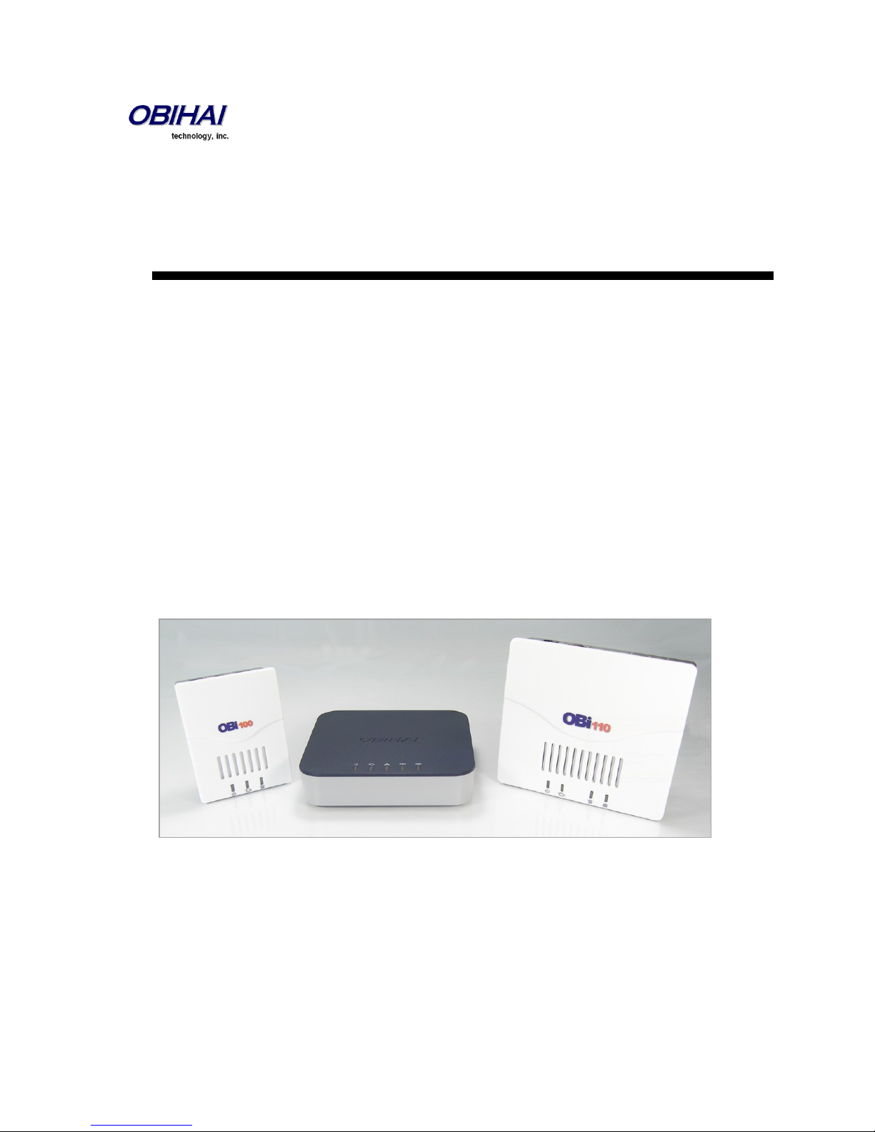
Models:
OBi1 Series – OBi100, OBi110
OBi2 Series – OBi200, OBi202
OBi3 Series – OBi300, OBi302
Version 01092013 – September 2013

INTRODUCTION 6
AUDIENCE 6
WHERE TO GO FOR HELP 6
NOTATIONAL CONVENTIONS 6
INTRODUCTION TO OBI DEVICES 8
PHYSICAL INTERFACES OF THE OBI DEVICE 10
OVERVIEW OF THE OBI DEVICE PHYSICAL INTERFACES 10
CONNECTING POWER TO THE OBI DEVICE 10
LED DESCRIPTION AND LED BEHAVIOUR 11
INTERNET CONNECTION SET-UP AND CONFIGURATION 13
PHONE PORT SET-UP AND CONFIGURATION 13
USING THE OBI AS A PAGING SYSTEM 13
PRIMARY LINE 14
LINE PORT SET-UP AND CONFIGURATION 15
FEATURES AVAILABLE ON THE OBI2 SERIES AND OBI3 SERIES MODELS 15
SHARING FILES ON AN EXTERNAL USB STORAGE DEVICE 15
IP ROUTING AND LAN SWITCHING FEATURES (OBI202 AND OBI302 ONLY) 16
END USER FEATURES AVAILABLE ON THE OBI 20
OBITALK WEB PORTAL: 20
OBI CIRCLES OF TRUST 20
OBION IPHONE & IPOD TOUCH + ANDROID SMART PHONE APPS 20
OBIAPP FOR PC SOFT PHONE APP 20
OBI WORKS WITH YOUR EXISTING SERVICES 20
BRIDGE YOUR SERVICES FOR OPTIMUM SAVINGS & CONVENIENCE 20
CALL FORWARDING 20
CALLER ID – NAME & NUMBER 21
CALL WAITING 21
3-WAY CALLING 21
CALL TRANSFER (ATTENDED) 21
NORDIC STYLE FEATURE INVOCATION 22
CALLER ID BLOCK (ANONYMOUS CALLING) 22
AUTOMATIC CALL BACK (CALL RETURN) 22
REPEAT DIALING 22
ANONYMOUS CALL BLOCK 22
DO NOT DISTURB 22
MESSAGE WAITING INDICATION – VISUAL AND TONE BASED 23
SPEED DIALING OF 99 OBI ENDPOINTS OR NUMBERS 23
PHONE 1/2 COLLABORATIVE FEATURES (OBI202 AND OBI302 ONLY) 23
STAR CODE FEATURES 24
CALL FORWARD NUMBERS 26
CONFIGURATION AND MANAGEMENT INTERFACES OF THE OBI DEVICE 27
TELEPHONE-IVR-BASED LOCAL CONFIGURATION 27
Copyright 2010-2013 Obihai Technology, Inc. 2

SYSTEM LEVEL CONFIGURATION OPTIONS 28
NETWORK RELATED CONFIGURATION OPTIONS 29
ROUTER RELATED CONFIGURATION OPTIONS (OBI202 AND OBI302 ONLY) 30
OBIWIFI NETWORK RELATED CONFIGURATION OPTIONS (OBI2 SERIES AND OBI3 SERIES ONLY) 31
SIP SERVICE PROVIDER CONFIGURATION OPTIONS 32
OBITALK CONFIGURATION OPTIONS 37
AUTO ATTENDANT CONFIGURATION OPTIONS 38
LINE (FXO) PORT CONFIGURATION OPTIONS 39
CUSTOMIZED AA PROMPT RECORDING OPTIONS 40
WEB SERVER-BASED LOCAL CONFIGURATION 41
WEB PAGE CONVENTIONS AND ICONS & BUTTONS: 42
FIRMWARE: LOCAL OBI DEVICE UPDATE AND MANAGEMENT 43
UPDATING FIRMWARE: 43
POSSIBLE ERROR MESSAGES ON FIRMWARE UPDATE FAILURE: 44
CUSTOMIZED AA PROMPTS BACKUP & RESTORE: 44
CONFIGURATION BACKUP & RESTORE: 44
RESET CONFIGURATION TO FACTORY DEFAULT 45
ZERO-TOUCH, MASSIVE SCALE REMOTE PROVISIONING: 45
ITSP QUICK START SETUP WIZARD (OBI100 AND OBI110) 46
ITSP QUICK START SETUP WIZARD (OBI202, OBI302) 49
STATUS PAGES 53
SYSTEM STATUS 53
LAN STATUS (OBI202/OBI302 ONLY) 57
CALL STATUS 59
CALL HISTORY 60
SERVICES, PHONE & LINE STATUS 61
ROUTER CONFIGURATION (OBI202, OBI302 ONLY) 64
WAN SETTINGS 64
LAN SETTINGS 68
DHCP RESERVATION 71
FIREWALL AND DMZ 72
PORT FORWARDING 73
QOS SETTINGS 74
OBIWIFI WIRELESS USB ADAPTER 77
WIFI SETTINGS 78
WIFI SCAN 80
SYSTEM MANAGEMENT FEATURES OF THE OBI DEVICE 81
NETWORK SETTINGS 81
AUTOMATIC FIRMWARE UPDATE & PROVISIONING 85
DEVICE ADMINISTRATION 91
DEVICE UPDATE 93
Copyright 2010-2013 Obihai Technology, Inc. 3

SIP SERVICE PROVIDER FEATURES OF THE OBI DEVICE 93
SIP REGISTRATION 94
SIP OUTBOUND PROXY SERVER 94
DNS LOOKUP OF SIP SERVERS 94
NAT TRAVERSAL CONSIDERATIONS 95
SIP PROXY SERVER REDUNDANCY AND DUAL REGISTRATION 95
SIP PRIVACY 96
STUN AND ICE 97
ITSP DRIVEN DISTINCTIVE RINGING 97
RTP STATISTICS – THE X-RTP-STAT HEADER 98
MEDIA LOOPBACK SERVICE 98
GOOGLE VOICE™ SERVICE 108
USING SPN AS A PROXY FOR A SIP IP PHONE 118
OBITALK SERVICE SETTINGS 119
AUTO ATTENDANT SERVICE 123
AUTOMATED ATTENDANT 123
AA CALLBACK SERVICE 123
USER RECORDED PROMPTS 124
CUSTOMIZING AA PROMPT LISTS 124
VOICE GATEWAYS 130
TRUNK GROUPS 132
OBIBLUETOOTH 133
PAIRING OBIBT WITH MOBILE PHONE 133
OBIBLUETOOTH CALL FEATURES 134
PHONE INTERFACE FEATURES OF THE OBI DEVICE 138
REPEAT DIALING SERVICE 138
TELEPHONE LINE INTERFACE FEATURES OF THE OBI DEVICE 150
LINE PORT STATUS EVENT PACKAGE 150
CODEC PROFILE FEATURES OF THE OBI DEVICE 156
TONE & RING PATTERNS 163
TONE PROFILE FEATURES OF THE OBI DEVICE 163
TONE EXAMPLES: 165
RING PROFILE A & B FEATURES OF THE OBI DEVICE 169
STAR CODE PROFILE FEATURES OF THE OBI DEVICE 175
STAR CODE SCRIPT VARIABLES (VAR) 175
STAR CODE SCRIPT ACTIONS (ACT) 176
STAR CODE SCRIPT FORMAT 177
STAR CODE SCRIPT EXAMPLES 177
USER SETTINGS FEATURES OF THE OBI DEVICE 181
Copyright 2010-2013 Obihai Technology, Inc. 4

SPEED DIAL NUMBERS 181
USING SPEED DIAL NUMBER AS AD HOC GATEWAY 181
USER DEFINED DIGIT MAPS 182
SHARING FILES ON AN ATTACHED EXTERNAL USB STORAGE DEVICE (OBI202 ONLY) 183
FILE SHARING SETTINGS 183
FILE EXPLORER 188
OBI CALL ROUTING AND DIGIT MAP 191
TRUNKS, ENDPOINTS, AND TERMINALS 191
SUPPORTED 2-WAY CALL BRIDGES ON THE OBI DEVICE 191
CALL ROUTING – THE OBI WAY 192
INBOUND CALL ROUTE CONFIGURATION 193
OUTBOUND CALL ROUTE CONFIGURATION 195
DIGIT MAP CONFIGURATION 197
DIGIT MAP RULES AND ELEMENTS 197
MATCHING AGAINST MULTIPLE RULES IN DIGIT MAP 199
INVOKE SECOND DIAL TONE IN DIGIT MAP 201
CHANGE INTER-DIGIT LONG TIMER DYNAMICALLY AFTER PARTIAL MATCH 202
USER DEFINED DIGIT MAPS 202
A USER DEFINED DIGIT MAP FOR IPV4 DIALING 202
SPECIFICATIONS & ENVIRONMENTAL CHARACTERISTICS OF THE OBI DEVICE 204
Copyright 2010-2013 Obihai Technology, Inc. 5

Introduction
Audience
Cloud Service Providers and Managed Service VARs
Note to End Users
End users are highly encouraged to use the OBiTALK web portal to configure and manage their OBi devices. The reason for
this is two-fold. One, the major benefits afforded by the OBi devices are available to be turned on, set-up and modified
from within the portal. What’s more is the application of the functional configuration is controlled by device configuration
files tightly integrated with the settings configured by the OBiTALK portal and cloud-based applications managed by Obihai
which make possible the device’s “plug-n-play” operation.
Where to Go for Help
Obihai has a number of options available to customers who are seeking help regarding their Obihai products.
Obihai Web Site:
1. Obihai Support Web Site: http://www.obihai.com/support.html
On this web site visitors will find links to the OBiTALK forum, Documents and Downloads, Tools Tips and Tricks as
well as an FAQ / Knowledge Base.
2. Enter a Support Request at: http://www.obihai.com/supportTicketForm.php
3. Go to the OBiTALK forum at: www.obitalk.com/forum
4. E-mail the Obihai Support Team at: support@obihai.com
Notational Conventions
An OBi device configuration parameter and value is represented in the style listed below:
Group Name::ParameterName = Parameter Value
Group Name is the heading of the parameter group on the left side panel of the device configuration web page and may
contain spaces. When a group heading has more than one level, each level is separated with a -, such as
Services Providers - ITSP Profile A – SIP::
ParameterName is the name of the parameter as shown on the web page and MUST NOT CONTAIN ANY SPACES.
Parameter Value is the literal value to assign to the named parameter and may contain spaces. Group Name or its
top level headings may be omitted when the context is clear. Examples:
SP1 Service::AuthUserName = 4082224312
ITSP Profile A - SIP::ProxyServer = sip.myserviceprovider.com
Copyright 2010-2013 Obihai Technology, Inc. 6
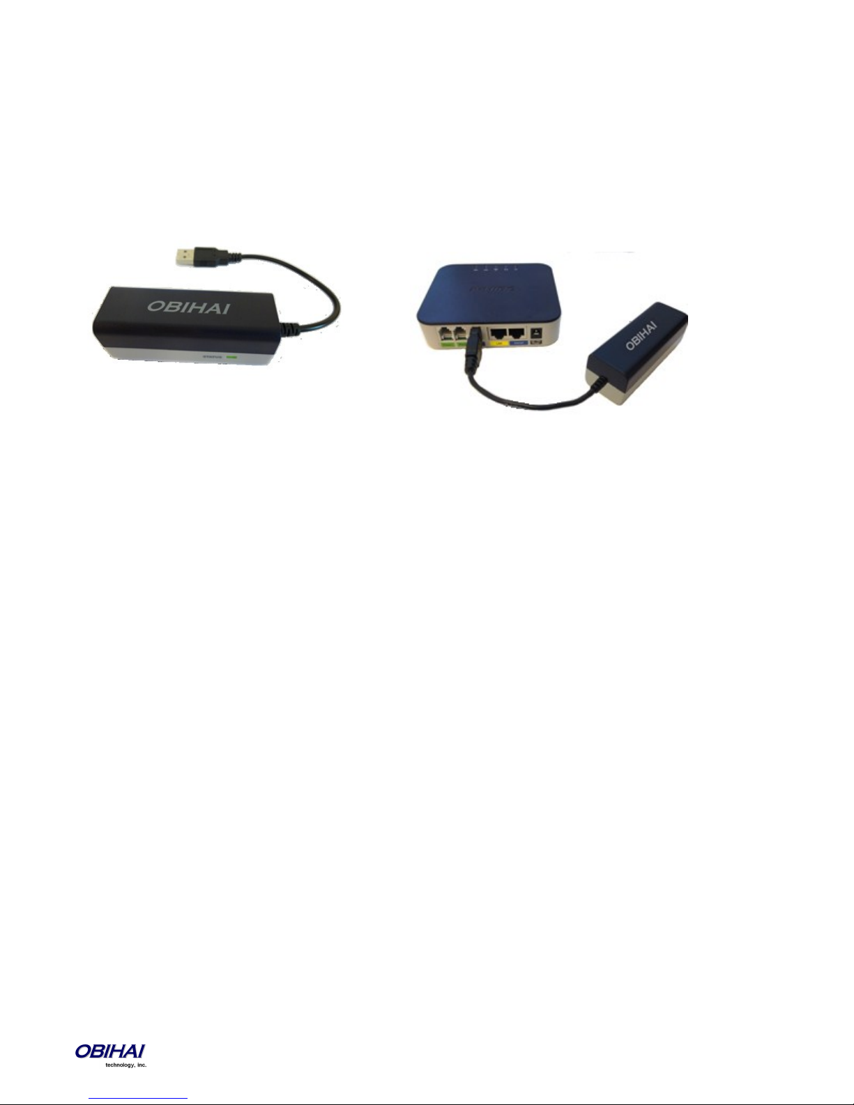
The OBi110 LINE Port and OBiLINE USB to FXO Adapter
A built-in LINE port is available only on the OBi110 model. For OBi models that have a USB Port, an OBiLINE USB to FXO
adapter accessory may be attached to provide an additional LINE port. As such, references in this document that describe
configuration or behavior of the LINE port or “Li” interface apply to the OBi110 or devices with an OBiLINE USB to FXO
adapter attached.
OBiLINE USB to FXO Adapter
Copyright 2010-2013 Obihai Technology, Inc. 7
Model
VoIP Account
Support
(SIP or Google Voice)
OBiTALK
Support
Phone
Port(s)
Line Port
Ethernet
Port(s)
USB
Port
OBi100
Yes – 2 Accounts
Yes 1 0 1 0
OBi110
Yes – 2 Accounts
Yes 1 1 1 0
OBi200
Yes – 4 Accounts
Yes 1 0* 1 1
OBi202
Yes – 4 Accounts
(SIP only)
Yes 2 0* 2 1
OBi300
Yes – 4 Accounts
Yes 1 0* 1 1
OBi302
Yes – 4 Accounts
(SIP only)
Yes 2 0* 2 1
Introduction to OBi Devices
Built with a high-performance system-on-a-chip platform to ensure high quality voice conversations, OBi devices are
dedicated systems targeted at applications for voice over IP services. OBi devices have high availability and reliability
because they are always-on to make or receive calls. With an OBi device, a computer is not required and a computer does
not need to be on to talk to people. To get started, all you need is a phone, power and a connection to the Internet.
OBi Devices:
*
You may connect an OBiLINE USB to FXO adapter to the USB Port of the OBi device to provide an extra Line port. In that case, many of the Line Port
related features and configuration parameters described in this guide will be applicable on that device.
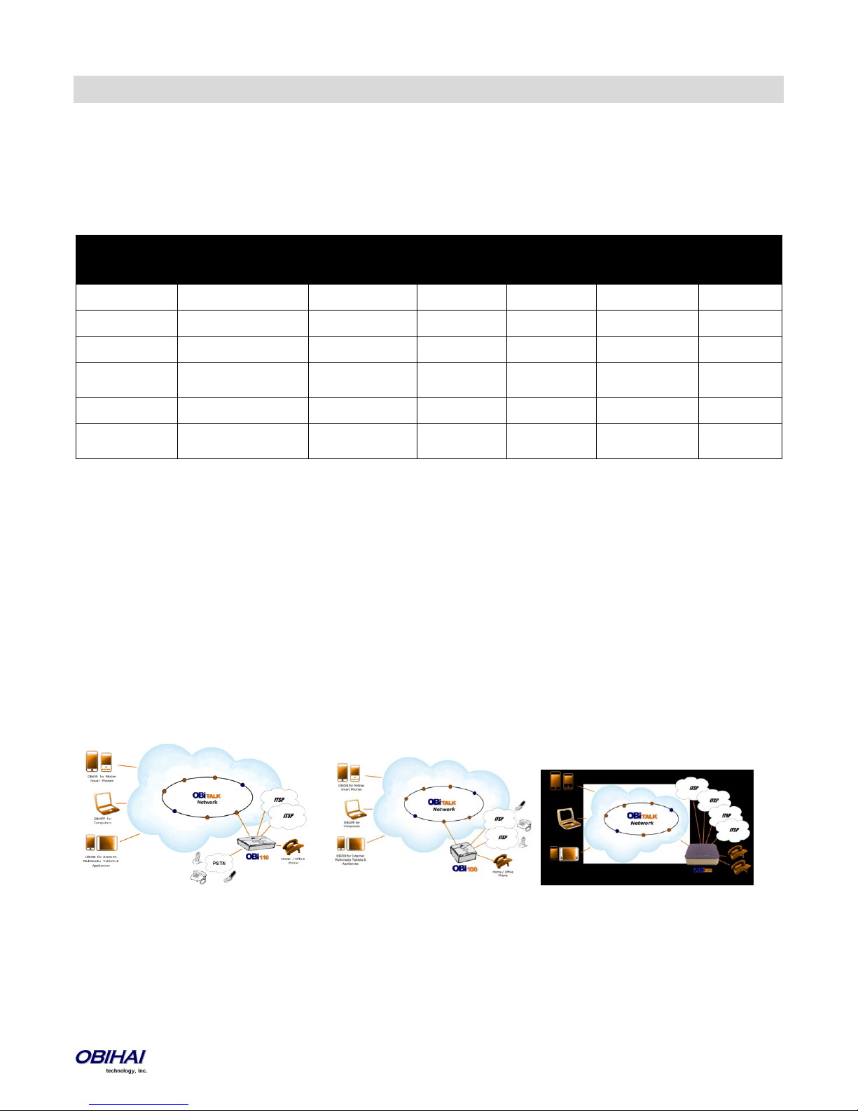
OBi Devices Are Complemented by Other OBi Products & Services
OBiTALK: A customer portal for device management allowing members to add people and associated OBi endpoints to
“circles of trust” such that additional functionality can be shared amongst authorized users. The OBiTALK portal is also
where members can download the OBiAPP and OBiON applications for PCs and the iPhone, iPad, iPod touch & Android
devices, respectively.
OBiON for iPhone, iPad, iPod touch & Android Devices: An application for iPhone, iPad, iPod touch and Android devices
which makes possible placing and receiving calls to/from other OBi endpoints.
OBiAPP for PC: An application for a PC that facilitates placing and receiving calls to/from other OBi endpoints.
Copyright 2010-2013 Obihai Technology, Inc. 8
Key Features of the OBi Voice Service Bridge / Telephone Adapter:
Google Voice Support for Up to Four (4) Google Accounts – 2 on the OBi1 Series, 4 on the OBi2 Series
- Google Voice Support Not Available on the OBi3 Series
SIP Service Provider Support for Up to Four (4) SIP Accounts – 2 on the OBi1 Series, 4 on the OBi2 and OBi3 Series
Any Available Service Can be Accessed from Each Phone Port Independently
Aggregation and Bridging of SIP and/or Google Voice, OBiTALK & Land Line (POTS) Services**
Automatic Attendant for Simplified Call Routing (AA)
Call Back Service – Automatic Call Back to Connect User to the AA to Make a New Call or Ring the Attached Phone
** Land line available on OBi110 or with OBiLINE accessory (OBiLINE works with OBi2 and OBi3 Series devices only.).
OBiTALK Web Portal Integration
Configuration and Management of OBi Endpoints
Download OBi Client Applications for PCs, Mobile Phones & Internet Devices
Creating & Joining Circles of Trust So You Can Share Your OBi
Setting Up Your OBi Endpoint Speed Dial Directory
Configurable to Work with Any SIP Compliant Internet Telephone Service or Google Voice Communications Service
Configurable to Work with Most Loop Start Analog Telephone Lines
Analog Phone & Telephone Line Impedance Agnostic
Robust Telephony Features:
Message Waiting Indication - Visual and Tone Based
Speed Dialing of 99 OBi Endpoints or Numbers
Three Way Conference Calling with Local Mixing
Hook Flash Event Signaling
Caller ID – Name & Number
Call Waiting
Call Forward - Unconditional
Call Forward on Busy
Call Forward on No Answer
Call Transfer
Anonymous Call
Block Anonymous Call
Do Not Disturb
Call Return
Repeat Dialing
Powerful Call Routing & Voice Service Features:
SIP Support for Voice and Fax Over IP from Internet Telephony Service Providers
OBiTALK Managed VoIP Network for OBi Endpoint Devices & Applications
High Quality Voice Encoding Using G.711, G.726, G.729 and iLBC (OBi200/OBi202/OBi300/OBi302 only) Algorithms
Recursive Digit Maps & Associated Call Routing (Outbound, Inbound)
Copyright 2010-2013 Obihai Technology, Inc. 9
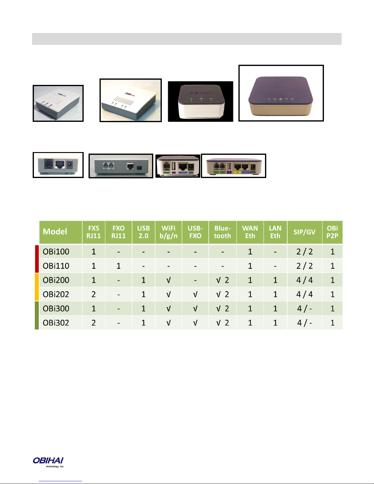
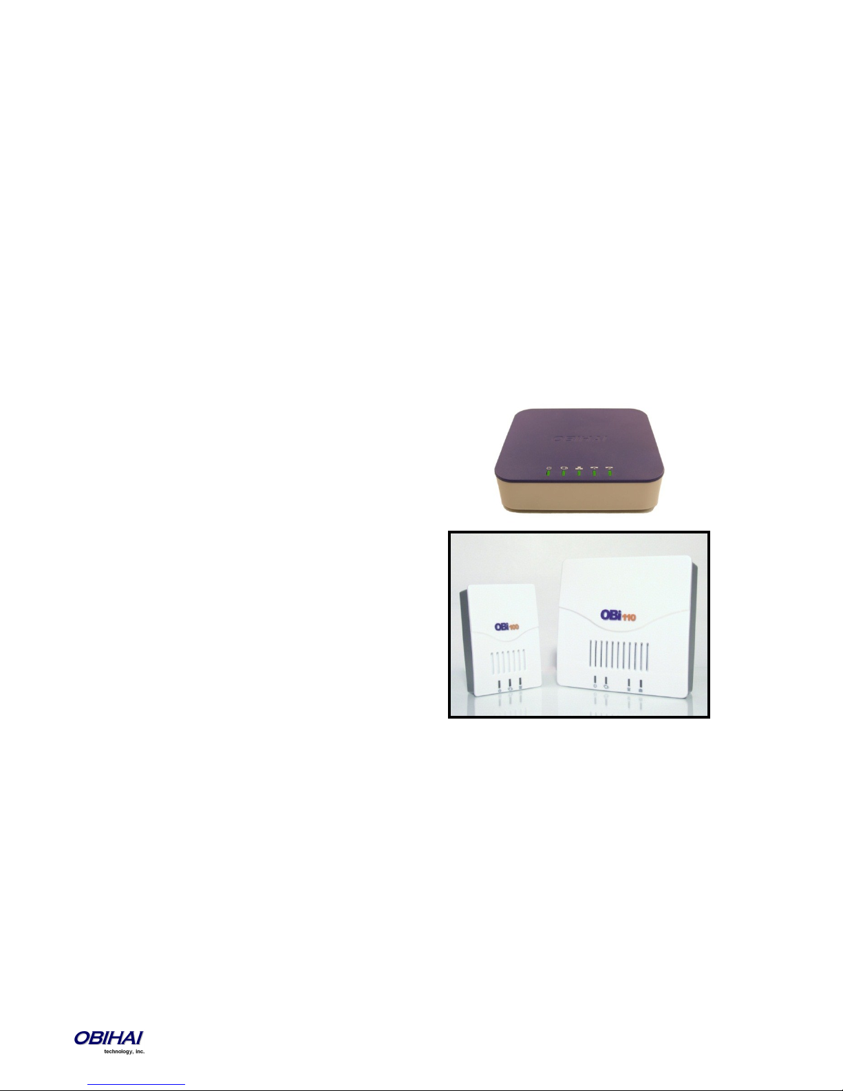
Physical Interfaces of the OBi Device
Overview of the OBi Device Physical Interfaces
Top Views of the OBi100, OBi110, OBi200/300 and OBi202/OBi302
LED Order (Left to Right): Power Status – Internet Port Activity – LAN Port Activity (OBi202) – PHONE Status – LINE Status (OBi110)
Rear Views of the OBi100, OBi110, OBi200/300 and OBi202/OBi302
Port Order (L-to-R): LINE Port (OBi110) – PHONE Port(s) – LAN Port (OBi202/OBi302) – Internet Port – 12v DC Power Jack
OBi Device Feature Comparison
- Up to 2 OBiBT devices may be used (USB hub required).
- FXO connectivity may be added to OBi2 and OBi3 Series devices with the OBiLINE USB to FXO adapter.
Connecting Power to the OBi Device
Connect the supplied 12-volt power adapter to the OBi device and the wall outlet or working power strip. Only use the
power adapter supplied with the original packaging to power the OBi device. Use of any power adaptor other than what
was provided with the OBi will void the warranty and may cause the unit to not function at all or cause undesired
operation.
Copyright 2010-2013 Obihai Technology, Inc. 10
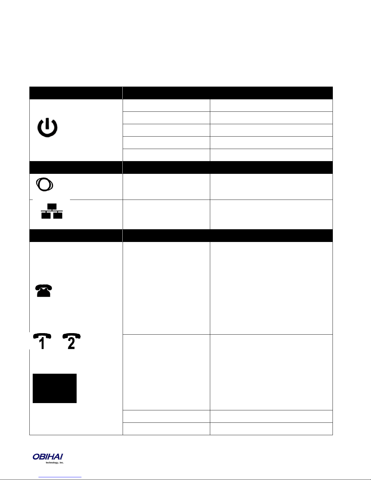
LED Icon
Light Behavior
What It Means
Off
The OBi is not receiving power.
Solid Green
The OBi is operational.
Flashing Green
The OBi is looking for a DHCP IP address.
Flashing Orange
The OBi is upgrading. DO NOT remove power!
Solid Red
The OBi is non-operational.
LED Icon
Light Behavior
What It Means
Flashing Green (Intermittent)
Light flashes when there is data activity on the
OBi Internet Ethernet port.
Flashing Green (Intermittent)
Light flashes when there is data activity on the
OBi LAN Ethernet port. (OBi202 Only)
LED Icon
Light Behavior
What It Means
OBi100 & OBi110:
OBi202 & OBi302:
OBi200/OBi300:
Off
The port is not enabled. Otherwise:
- If the Primary Line is the
PSTN LINE, indicates OBiTALK
service is not available.
- If Primary Line is
SP1/SP2/OBiTALK, indicates
the corresponding primary
service is not available (but
the secondary services may
still be available).
Solid Green
The phone is ready to be used:
- If the Primary Line is the
PSTN LINE, indicates OBiTALK
service is available.
- If the Primary Line is
SP1/SP2/OBiTALK, indicates
the corresponding primary
service is available.
Flashing Green
The phone is in use.
Fast Flashing Green
The phone is ringing.
LED Description and LED Behaviour
There are four (4) LED lights on the top of the OBi. They are used to provide the user with a visual indication of the working
order and general status of key functional aspects of the OBi device. Under normal operating conditions the LEDs should
show green (solid or blinking) signals.
Here below, are specific details/explanation of the OBi LED description and behaviour.
Copyright 2010-2013 Obihai Technology, Inc. 11
Programmable using the phone
port’s MWILedTimer parameter
Available on Obi2 Series and
Obi3 Series Only
New voicemail available (MWI)
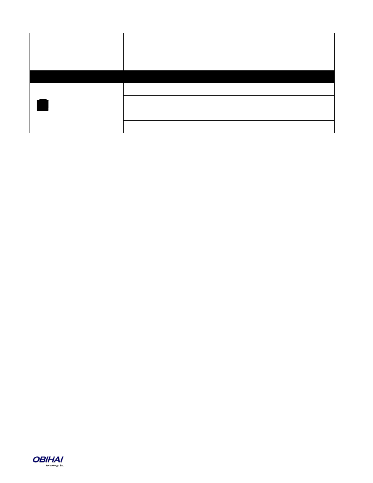
LED Icon
Light Behavior
What It Means
OBi110 Only
Off
The port in not enabled.
Solid Green
The line is ready to be used.
Flashing green
The line is in use.
Fast Flashing Green
The line is ringing.
LED Pattern When Hardware Reset Button Is Pressed for Ten (10) Seconds:
Power LED blinks green slowly for 5 seconds and fast for 4 seconds preceding unit reboot.
Copyright 2010-2013 Obihai Technology, Inc. 12

Internet Connection Set-Up and Configuration
Connect one end of an Ethernet cable to the OBi INTERNET port and the other end of the Ethernet cable to an Ethernet port
on your Internet router or Ethernet switch. By default the OBi will request an IP, DNS and Internet (WAN) Gateway IP
addressing via DHCP.
PHONE Port Set-Up and Configuration
A phone has a very basic UI (User Interface) for I/O (Input / Output) of signalling or control messages.
The OBi PHONE port supports input signalling and control messages comprised of: On Hook, Off Hook, Hook Flash, DTMF
tones.
The OBi PHONE port supports output signalling and control messages comprised of: Caller ID/CWCID, MWI, DTMF/Tone,
Ring, Pol-Rev, CPC, Power Denial.
The OBi PHONE port has a Maximum Sessions capacity of two (2). This is not configurable.
The OBi PHONE port will reply BUSY to a new incoming call when:
The PHONE port already has 2 calls in session.
The PHONE port is ringing the phone.
The phone is in a dialing or fast busy “Invalid” state.
The OBi is already in a FAX call.
The OBi PHONE port supports Call Waiting when a 2nd call is an inbound call:
A Hook-Flash (or depressing the Flash button) invokes switching between two (2) calls.
When the OBi PHONE port goes On-Hook this will end current call and invoke a ring for the holding call.
The OBi PHONE port supports 3-way Calling when the second call is an outbound call.
On the first Hook-Flash during an active call the OBi can make a second outbound call.
On the second Hook-Flash, the first call and the second outbound call are placed in a conference.
To remove the second conferenced party, invoke a third Hook-Flash.
When the OBi goes On-Hook during a 3-way Call, this will become a transfer when 2nd (outbound) call is ringing or
connected. If the 2nd (outbound) call does not succeed, e.g. no answer or busy, then the OBi PHONE port can go to an On
Hook state and will ring as the holding call is still on the line, or simply Hook-Flash to resume the first call.
The OBi PHONE port can select from the following services to which it can complete a call: SP1 Service (SP1), SP2 Service
(SP2), SP3 Service (SP3), SP4 Service (SP4), OBiBlueTooth 1 Service (BT1), OBiBlueTooth 2 Service (BT2), OBiTALK Service
(PP1), and PSTN Line (LI1).
PHONE PORT::DigitMap
PHONE PORT::OutboundCallRoutes
PHONE PORT::CallReturnDigitMaps
Using the OBi as a Paging System
You may connect the OBi PHONE port to an external PA system via an RJ11-to-Line-Out connector (available at many
popular electronics shops), and enable the PHONE port option UseForPagingOnly. In this configuration, the phone port is
expected to be “off-hook” all the time. The OBi will automatically answer incoming calls. It will not accept call-waiting.
Copyright 2010-2013 Obihai Technology, Inc. 13

1
When the phone port goes from on-hook to off-hook, in case the user needs to dial * * * to invoke the IVR, the OBi will play
a dial tone for 5 seconds. After 5 seconds the OBi will turn silent and be ready to accept an incoming call to page.
Primary Line
By default, devices which come with an analog (PSTN) line port will use this as the Primary Line for outbound calls made
from the PHONE port and via the OBi Auto Attendant. This means that when you dial a new number using the AA, you do
not need to first dial a service route access code. You can select the Primary Line for the PHONE port and for the AA,
respectively, using the parameters PHONE Port::PrimaryLine and Auto Attendant::PrimaryLine.
Depending on the device model, you may add up to two (2) or four (4) SP VoIP services to the OBi, and attach a PSTN line to
the LINE Port as an additional voice service. The VoIP services can be SIP-based services or the Google Voice service (SIP
only on OBi302 and OBi300). In addition, all device models come with the free OBiTALK (peer-to-peer) service. In this
document we sometimes refer to any one of these voice services as a trunk. A trunk group (TG) is a (comma-separated)
ordered list of trunks. If a TG is selected for making an outbound call, the OBi will pick the first available member in that
trunk group for the call. Up to four (4) TGs can be defined in an OBi (see the section Trunk Groups for detail).
You can make one of the available trunks or TG1 as the Primary Line for outbound calls. The Primary Line for the PHONE
port(s) and the Auto Attendant is configured via the OBi device management web page described herein or the OBiTALK
Device Configuration VoIP Service Provider set-up screen also gives the user the option to select a trunk or TG1 as the
Primary Line. The list below summarizes the choices available for selection as the primary line:
SP1 Service
SP2 Service
SP3 Service
SP4 Service
OBiTALK Service
PSTN Line1
OBiBlueTooth1
OBiBlueTooth 21
Trunk Group 1
Trunk Group 21
When you want to make a call via a service that is not the Primary Line, you will need to dial that service’s access code
before the destination number.
The default service route access codes are defined as:
** 1 : SIP Service Provider 1 or Google Voice Service 1 (SP1)
** 2 : SIP Service Provider 2 or Google Voice Service 2 (SP2)
** 3 : SIP Service Provider 3 or Google Voice Service 3 (SP3)
** 4 : SIP Service Provider 4 or Google Voice Service 4 (SP4)
** 8 : PSTN Line Port Service (LI) on OBi1101
**70: PSTN Line Port Service (LI) on OBi200/OBi202/OBi300/OBi3021 Requires OBiLINE Accessory
**8 or **81: OBiBlueTooth 1 Service (BT1)1
**82: OBiBlueTooth 2 Service (BT2)1
A dedicated LINE Port is available only on the OBi110 or devices with an attached OBiLINE USB to FXO adapter accessory. OBiBlueTooth is available only
on devices with an attached OBiBT USB adapter accessory. OBiBlueTooth 2 is available only on devices with two OBiBT USB dongles attached. Trunk Group
2 is not available as a choice of primary line on OBi100/OBi110.
Copyright 2010-2013 Obihai Technology, Inc. 14

** 9 : OBiTALK Network (PP)
Service route access codes for calling from the PHONE port can be customized if necessary by modifying PHONE
Port::DigitMap and PHONE Port::OutboundCallRoute. Service route access codes for calling via the Auto
Attendant can be customized if necessary by modifying Auto Attendant::DigitMap and Auto
Attendant::OutboundCallRoute.
Note: Occurrences of (Mpli) and pli are substituted internally with the corresponding abbreviated trunk name of the
selected primary line.
LINE Port Set-Up and Configuration
Like a PHONE port, a LINE port has a basic UI (User Interface) for I/O (Input / Output) of signalling or control messages:
The OBi LINE port supports the following inputs: DTMF, Polarity, CPC, Caller ID, Ring, Tone
The OBi LINE port supports the following outputs: DTMF/Tone, On Hook, Off Hook, Hook Flash*
The OBi LINE port will assume a call is Connected on the following conditions:
End of dialing for outbound calls
Off-hook for inbound calls
The OBi LINE port will assume a call is Disconnected on the following conditions:
Power Down, CPC, Long Silence, or Disconnect Tone
Note: The OBi LINE port and system logic will not attempt to invoke or interpret PSTN supplementary services. This is
directly between the user and the Phone Company.
To signal hook-flash to the PSTN Line during a call from the phone attached to the PHONE port, Phone
PORT::HookFlashHandling must be set to Send Flash Hook to PSTN
Features Available on the OBi2 Series and OBi3 Series Models
Sharing Files on an External USB Storage Device
The OBi2 Series models have a USB port that can be attached to an external USB storage device, such as a USB flash drive or
USB hard disk drive. The device’s native web server includes functionality for browsing the contents on the attached USB
device and sharing them selectively with other parties.
There are three levels of access to an attached USB storage device, admin, user, and anonymous. Admin and user level
access are protected by a User ID and Password. The admin will have full access while a user level access can be restricted.
Anonymous access is limited to read-only without being prompted by the OBi device to enter a User ID or Password. To
have admin level access, one must login with the User ID “admin” and provide the corresponding password. To login as a
user, one must login with a valid User ID and provide the corresponding password. Up to 10 User IDs can be specified in the
OBi device’s configuration for user level access, and each User ID can be enabled individually and assigned a different set of
restrictions with the following attributes:
Home Directory: This specifies where in the device directory tree the user nay start browsing.
File Filter: This specifies which file types the user can see and manipulate. File filters are limited to filename
suffixes such as *.jpg; *.mp3
Write Enable: This specifies whether the user can upload, delete, copy, cut and paste files or create new
directories on the USB device. Note: By default, read/file-download access is granted to all users.
Copyright 2010-2013 Obihai Technology, Inc. 15

Use the following URLs on a web browser to launch the OBi File Explorer:
For anonymous level access: http://<OBi-IP-Address>/obi_share/anonymous
For admin or user level access: http://<OBi-IP-Address>/obi_share
The File Explore can be launched from either the WAN or LAN side of the OBi. The WAN side access can be disabled in the
configuration.
IP Routing and LAN Switching Features (OBi202 and OBi302 Only)
OBi202 and OBi302 have two Ethernet ports labelled as the Internet port and the LAN port. The OBi works as a router by
default. All the native voice services and features use the WAN port only when the OBi202/OBi302 is in router mode. The
OBi can also be set to work as a 3-port switch (a.k.a. Bridge mode), by changing its OperationMode parameter from Router
to Bridge. Note: One of the switch ports is for OBi202/OBi302 internal use only.
IP Routing Features
In router mode we refer to the network connected to the OBi Internet Port as the WAN side of the OBi202/OBi302, and the
network connected to the OBi LAN Port the LAN side of the OBi. The WAN side may be connected to another Ethernet
switch or directly to an access device such as a cable or DSL modem for Internet access. The OBi202/OBi302 routes traffic
between the LAN side and the WAN side, thus allowing the devices (such as PCs) attached to the LAN side to share Internet
access. The OBi202/OBi302 supports subnet masks as big as 255.255.255.0 to accommodate up to 253 IP addresses on its
LAN side subnet.
In addition to being a NAT (Network Address Translation) router, the OBi202/OBi302 includes a DHCP server, a DNS
forwarder and a basic firewall. It supports port forwarding, DMZ, QoS, and VLAN (802.1q). The maximum routing
throughput between the WAN and the LAN side is approximately 30 Mbps. This speed can be achieved when there are no
active calls in the system. Otherwise the throughput will be limited to a slower speed to accommodate the load for voice
processing. Note that if the WAN side is connected to an Internet access device directly, then the throughout could be
further limited by the speed of the Internet uplink and downlink.
The OBi202/OBi302 will acquire its WAN side IP address using one of the following methods: Static Address Assignment,
DHCP, or PPPoE. By default, the OBi202/OBi302 acquires its WAN side IP address using DHCP. Also by default, the
OBi202/OBi302’s own DHCP server is enabled to support LAN side clients, e.g. PCs. The default LAN side IP address of the
router is 192.168.10.1.
Incoming packets receiving from the WAN side are forwarded by the router according to the following flow:
If firewall is enabled, discard the packet if it is rejected by any one of the active firewall components
If the sending host address matches a valid entry in an internal host binding table, queue the packet for local
processing. This binding table is updated by the router with an internal algorithm.
If the sending host address matches a valid entry in an internal NAT binding table, forward the packet to the
corresponding LAN IP address. The NAT binding table is updated by the router with an internal algorithm.
If the receiving port and protocol matches a reserved pair to support an internal process (e.g. TCP Port 80 for the
OBi202 web server process), queue the packet for local processing.
If the receiving port and protocol matches a port forwarding rule, forward the packet to the LAN IP address
according to that rule.
If a DMZ host is configured, forward the packet to that LAN IP address.
Queue the packet for internal processing.
Copyright 2010-2013 Obihai Technology, Inc. 16

DHCP Server
By default, the built-in DHCP server is enabled on the OBi202/OBi302. It assigns IP address, network mask, DNS server and
default gateway address to the DHCP clients on the LAN side. The default gateway and DNS server have the same IP address
as the LAN side IP address of the router. In the DHCP server configuration, you may select the range of client IP addresses to
give out the Lease Time and the Local Domain Name. Furthermore, by using the DHCP reservation feature, you may reserve
specific IP addresses for some devices with specific MAC addresses. With this, those devices can always be assigned the
same IP addresses reserved for them each time they make a request to the DHCP server. See the LAN Settings and DHCP
Reservation sections for more details.
Firewall
The firewall protects local processes and LAN side clients against certain basic threats from the WAN side (or the Internet),
such as port scanning and a DOS (Denial of Service) attack. The firewall settings also allow you to selectively turn on or off
the following related features:
NATRedirection – Supports NAT Redirection (a.k.a NAT Loopback or Hairpin) if enabled (default is disabled).
DRDOSAttackProtection – Protects against DOS attack if enabled (default is disabled).
VPNPassThrough – Blocks all VPN traffic if disabled (default is enabled).
The settings of these features will take effect only if firewall is enabled. Otherwise, they will take on their respective default
values (that is, no NATRedirection or DRDOSAttackProtection and VPNPasssThrough is allowed).
Port Forwarding
Up to 20 port forwarding rules may be defined on the OBi. For each rule a range of ports and a designated receiving LAN IP
address must be specified such that incoming traffic arriving at any of those ports on the WAN side are forwarded to the
same port at the designated IP address on the LAN side. You may also specify for each rule if it should only apply to packets
transported over UDP, TCP or both.
DMZ
The DMZ host in the router is the default LAN client address to which a packet received from the WAN side is forwarded
when the router fails to find a matching LAN IP address or matching local process to forward the packet to. Note if firewall
is enabled, that the packet is still subject to firewall inspection before forwarding to the DMZ host.
QoS
QoS (Quality of Service) refers to the prioritization of network traffic based on the type of traffic. For example, time critical
traffic such as VoIP may be allocated the highest priority so they can have a better chance of on time delivery to the
destination. On the OBi202, QoS policy applies to upstream traffic (LAN-to-WAN) only. Downstream QoS is entirely up to
the ISP / upstream routers and switches. The upstream traffic is prioritized according to its type of service as indicated by
the DiffServ/TOS bits in the IP header of each packet. In the QoS settings, you may map the 64 possible types of service to
one of the three priority classes: High, Medium and Low. You may also specify the guaranteed minimum upstream
bandwidth for each priority class. LAN side clients indicate the desired priority class of their outbound packets to the router
by marking the DiffServ/TOS bits of their packets accordingly. See the QoS Settings section for more details.
Copyright 2010-2013 Obihai Technology, Inc. 17

In addition to the three priority classes, a fourth priority class known as the Restricted class is available. The Restricted class
has the highest priority among the four classes. The guaranteed bandwidth for the Restricted class is allocated separately
with its own parameter in the configuration.
Note that the total guaranteed bandwidth allocated to all the four priority classes is equal to the total available uplink
bandwidth, which must be specified correctly in the UpStreamBandwidth parameter in the QoS settings for QoS to work
properly.
Copyright 2010-2013 Obihai Technology, Inc. 18

VLAN Support in Router Mode
In router mode, the OBi202/OBi302 can support VLAN (802.1Q) on the WAN side. When VLAN is enabled, incoming packets
from the WAN side not belonging to the same VLAN are dropped, while all outgoing packets to the WAN side are tagged
with the configured VLAN ID. The VLAN support is transparent to the devices on LAN side. The router removes the VLAN
tag when forwarding packets to the LAN side.
LAN Switching Features
Instead of acting as a router, the OBi202/OBi302 can be set to work as a 3-port switch. One of the ports is internal and is
used by the OBi202/OBi302 CPU only, while the two external ports (labelled as Internet and LAN) can be connected to other
devices. This mode of operation is known as the bridge mode. In this mode, all the router features, such DHCP server,
firewall and port forwarding, will not take effect. The QoS policy in this case is hardwired such that the native voice and
related traffic will always have highest priority (this behavior is not configurable). Furthermore, accessing the OBi device
management web pages from either of the two external ports is always allowed.
VLAN Support in Bridge Mode
When VLAN is enabled, packets sent to the OBi not belonging to the same VLAN are dropped, while packets sent by the OBi
are tagged with the configured VLAN ID. The packets switched directly between the external ports, on the other hand, are
not modified by the OBi.
Copyright 2010-2013 Obihai Technology, Inc. 19

End User Features Available on the OBi
OBiTALK Web Portal:
The OBiTALK Web Portal allows you to manage your OBi endpoints and their relation to other endpoints in your Circle of
Trust. OBiTALK is a web portal and OBi configuration utility which helps OBi users configure devices for optimum savings
and access applications which make using OBi with even more convenience.
OBi Circles of Trust
The OBiTALK Web Portal is also where you can set-up Circles of Trust. The Circles of Trust provide a means to team-up with
other people with OBi devices and endpoints so that everyone’s calls can be made as inexpensively as possible.
OBiON iPhone & iPod Touch + Android Smart Phone Apps
After setting up an account and logging in to the OBiTALK portal, users may download applications for their iPhone and
Android smart phones.
OBiAPP for PC Soft Phone App
After setting up an account and logging in to the OBiTALK portal, users may download applications for their iPhone and
Android smart phones.
OBi Works with Your Existing Services
If you do not want to configure a new service in order to make free calls using your Internet connection you can simply plug
in your existing analog line from your telco phone service or connect the line coming from an VoIP service (from an ATA or
cable EMTA) to the OBi. Connect your telephone to the OBi’s phone port and you are ready to call other users’ endpoints
on the OBiTALK network.
Bridge Your Services for Optimum Savings & Convenience
With the OBi device, you can bridge multiple services to route calls in the most efficient cost-effective way. You can
connect your telco phone service to the OBi at your house and use your PC or Apple iPhone, iPod touch or Android Smart
phone to bridge a call from the OBiTALK network to the phone landline or Internet phone service connected to the OBi
device at home.
Call Forwarding
Call Forwarding allows you to send incoming calls to another number of your choosing. Calls can be forwarded to a number
reachable from the landline service, VoIP service or OBiTALK network. The following types of call forwarding are possible
with the OBi:
Call Forward ALL: When you use Call Forward ALL, all calls are immediately forwarded to the number you indicate when
you turn on the feature. To enable Call Forward ALL, from a phone attached to the OBi, dial *72. You will be prompted to
enter the number to which the calls will be forwarded. Dial the number plus the # key and a confirmation tone will be
heard. To disable Call Forward ALL, dial *73. A confirmation tone will be heard.
Call Forward on Busy: When you use Call Forward on Busy, all calls are forwarded to the number you indicate only when
you are already engaged in a call with your phone attached to the OBi. To enable Call Forward on Busy, from a phone
attached to the OBi, dial *60. You will be prompted to enter the number to which the calls will be forwarded. Dial the
number plus the # key and a confirmation tone will be heard. To disable Call Forward on Busy, dial *61. A confirmation tone
will be heard
Copyright 2010-2013 Obihai Technology, Inc. 20

Call forward on No Answer: When you use Call Forward on No Answer, all calls are forwarded to the number you indicate
only when you do not answer the call with your phone attached to the OBi. To enable Call Forward on No Answer, from a
phone attached to the OBi, dial *62. You will be prompted to enter the number to which the calls will be forwarded. Dial
the number plus the # key and a confirmation tone will be heard. To disable Call Forward on No Answer, dial *63. A
confirmation tone will be heard.
Caller ID – Name & Number
Caller ID allows you to see the number and (if available) the name of the person calling you. You can use this information to
decide whether or not to answer the call. You must have a phone (or device) that supports caller ID to use this feature.
Call Waiting
Call waiting lets you take a second call that comes in when you are already on the phone with another party and not have
to disconnect to take the new call. When you are on the line with the first party, you will hear a tone signalling you there is
a second call coming in. To answer this call, press the “flash” button on your phone or depress and release the switch hook
on the telephone. The first party will be placed on hold and you will be connected to the second party until you press the
“flash” button or depress and release the switch hook again.
Since Call Waiting can interfere with fax calls already in progress, it is advised that you configure your fax machine to dia l
the Cancel Call Waiting code before it dials the destination fax machine.
3-Way Calling
3-Way Calling allows you to talk to two parties at the same time with everyone on a telephone at a different location. To
use 3-Way Calling, when you are in a call with another party and want to add a second to the conversation, press the
“flash” button or depress and release the switch hook on your phone. You will be presented with a second dial tone and
the first party will be placed on hold. Dial the second party. When they answer, you will be able to inform them that you
intend to connect them with the first party (now on hold) and have a conference. At this point press the “flash” button or
depress and release the switch hook on your phone. This will connect the first party, the second party and yourself. You
can all continue to talk together.
Call Transfer (Attended)
You can transfer a call to a third party using the attended transfer capabilities of the OBi. To use Attended Call Transfer,
while in a call with the party who will be transferred, press the “flash” button or depress and release the switch hook on
your phone. You will be presented with a second dial tone. The party who will be transferred will be placed on hold. Dial
the transfer target. When the transfer target answers, you will be able to inform them that you intend to connect them
with the party on hold. At this point press the “flash” button or depress and release the switch hook on your phone. This
will connect the party to be transferred, the transfer target and yourself. You can continue to talk together, as this is no w a
3-way call, or you can hang up the phone and the other two parties will remain connected.
Copyright 2010-2013 Obihai Technology, Inc. 21

Commands
Operations
Scenarios
R0
Reject the 2nd incoming call
1st call connected, 2nd call ringing
R1
End the 1st call. Resume or answer the 2nd call
1st call connected, 2nd call on
hold or ringing
R2
Hold 1st call. Resume or answer the 2nd call (swap
calls)
1st call connected, 2nd call on
hold or ringing
R3
Keep the 1st call. Resume or answer the 2nd call
(conference)
1st call connected, 2nd call on
hold or ringing
R4
Transfer 2nd call peer to the 1st call peer
1st call connected, 2nd call on
hold or connected
Nordic Style Feature Invocation
In the above description of call waiting, 3-way calling, and call transfer operations, the way the features are invoked is
referred to as N. America style. In Nordic regions (such as Sweden, Norway), the same features are invoked by hook flashing
followed by a digit 0, 1, 2, 3, or 4 to more precisely control which operations to apply to the calls. For these regions, the
phones may also be equipped with an R button for hook flashing. The commands issued to the OBi are referred to as R0, R1,
R2, R3, R4, and R5. Here is a summary of the operations:
To select the Nordic style of feature invocation, set the parameter PHONE Port::CallCommandSignalMethod to “Nordic
Regions (R1, R2, …)”. The default is: N. America.
Caller ID Block (Anonymous Calling)
Caller ID Block allows you to mask your name and number information from appearing on the phone you are calling. To use
Caller ID Block for one call only, dial *67 and then the destination number. To use Caller ID Block on a persistent basis, dial
*81 from the handset attached to the OBi. All calls will use the Caller ID Block feature until you cancel the Caller ID Block.
To cancel Caller ID Block, dial *82 from the handset attached to the OBi.
Note: This service feature requires ITSP support. While most ITSP services support this service feature, at present, Caller ID
Blocking is NOT available with Google Voice service.
Automatic Call Back (Call Return)
Automatic Call Back, also called Call Return can be used to call back the last caller who called you without actually dialing
their number. To use Automatic Call Back, from the phone attached to the OBi, dial *69. The OBi will then attempt to use
the previous callers Caller ID information to make the call.
Repeat Dialing
Repeat Dialing is useful when you call a number that is busy and you want to keep trying so that your call gets through
when the far end is available. Repeat dialing will continue to try the last number until the OBi device can complete the call
or Repeat dialing is cancelled. To enable repeat dialing, from the phone attached to the OBi, dial *05 and hang up. To
cancel repeat dialing, from the phone attached to the OBi, dial *06.
Anonymous Call Block
Anonymous Call Block allows you to block calls from incoming callers when there is no identifying caller ID name or number.
Incoming calls will be presented with a busy signal. To use Anonymous Call Block, from the phone attached to the OBi, dial
*77. To cancel Anonymous Call Block, from the phone attached to the OBi, dial *87.
Do Not Disturb
Copyright 2010-2013 Obihai Technology, Inc. 22

Do Not Disturb (DND) allows you to set the phone to immediately forward calls made to your OBi to the number set-up as
your voicemail number / account. If no voicemail account is set-up, the OBi will return a busy signal to the caller until you
turn off DND. To turn on DND, from a phone attached to the OBi, dial *78. To turn off DND, from a phone attached to your
OBi, dial *79.
Message Waiting Indication – Visual and Tone Based
Message Waiting Indication allows you to be notified when there is a new voice message for you. The OBi supports both
Visual and Tone based Message Waiting Indication. With Tone-based Message Waiting Indication, you will know there is a
message for you when you hear a “stutter” dial tone right when you first pick up the phone to make a call. Typically, this
stutter tone will be removed once you listen to your message(s). Visual-based Message Waiting Indication will turn on a
light or screen icon on your phone (or phone base station) when there is a message waiting for you. Typically, this light or
icon will go dark when you have listened to your new message(s).
Speed Dialing of 99 OBi Endpoints or Numbers
The OBi device supports Speed Dialing of 99 numbers. These numbers can be associated with phones reachable via an
Internet or landline service or the OBiTALK network. Be careful with the Speed Dial Set-Up as this will conflict with the
Speed Dials set-up on the OBiTALK portal. The Speed Dials that are set-up on the OBiTALK portal will always overwrite
anything set-up via the phone connected to the OBi.
PHONE 1/2 Collaborative Features (OBi202 and OBi302 Only)
While PHONE 1 and PHONE 2 can function independently of each other, the OBi202 and OBi302 also offer some
collaborative features to let the two phone ports work together as a mini phone system.
With the factory default digit map and call routing rules, you can dial a single “#” (pound/hash) digit to call from one phone
port to ring the other phone port. Depending on the current state of the called phone, one of the following can happen:
1. If the called phone is idle (on-hook), it will ring normally with a special Caller-ID that indicates the call is from the
other PHONE Port.
2. If the called phone is already on a call, the calling phone will barge in to join the call.
3. If the called phone is on-hook with a call on-hold, the calling phone will pick up and resume that call.
4. If the called phone is ringing, the calling phone will pick up and aswer that call.
5. For all other scenarios, the calling phone will hear busy tone.
Note that you can prevent the calling phone port from doing 2, 3 and 4, as they can be disabled by setting the parameter
EnablePhonePortBargeIn to false for that port. In that case, 2 will become normal call-waiting on the called phone, but the
calling phone will hear busy tone for 3 and 4.
You can also transfer an external call from PHONE 1 to PHONE 2 the usual way: while connected on an external all, hook
flash and dial # to ring the other phone, then hang up to transfer when the caller phone rings or answers.
For incoming calls on any trunk (SP1-4 or OBiTALK Service), one can set up the corresponding inbound call route to ring just
PHONE 1 or PHONE 2 or both. The default inbound call routes are setup to ring both phone ports.
For outgoing calls, each phone port has its own digit map and outbound call route configuration, which means that you
have the full flexibility in allocating trunks for making calls from each port independently. Each port may also have a
different primary line assigned; the default however is to set the prmary line to SP1 for both phone ports.
Copyright 2010-2013 Obihai Technology, Inc. 23

Star Code Features
The OBi device supports service features via the handset connected to the PHONE port. The following Star Codes can be
used to access the indicated features. OBi Star Code Enabled Features Apply to All Voice Services.
*03, Request peer device to loopback media in the next outbound call
*04, Request peer device to loopback RTP packets in the next outbound call
*05, Tell device to periodically redial the last called number until the called party rings or answers
*06, Cancel the last repeat dial request
07 Redial
*
69 Call Return
*
81 Block Caller ID (Persistent Mode)
*
82 Unblock Caller ID (Persistent Mode)
*
67 Block Caller ID (One Time)
*
68 Unblock Caller ID (One Time)
*
72 Call Forward All (Enter Number + #)
*
73 Disable Call Forward All
*
60 Call Forward on Busy (Enter Number + #)
*
61 Disable Call Forward in Busy
*
62 Call Forward on No Answer (Enter Number + #)
*
63 Disable Call Forward No Answer
*
77 Block Anonymous Calls
*
87 Unblock Anonymous Calls
*
56 Enable Call Waiting
*
57 Disable Call Waiting
*
78 Do Not Disturb – Turn On
*
79 Do Not Disturb – Disable
*
66 Repeat Dial
*
86 Disable Repeat Dial
*
74 Speed Dial Set-Up (Enter SD No. [1-99] then Tel No. + #) ∞
*
75 Speed Dial Read-Back (Enter SD No.)
*
*76, Clear a Speed Dial
*96, Barge In
*98, Blind Transfer
*4711, Use G711 Only on the next outbound call
*4729, Use G729 Only on the next outbound call
*28, Make OBiBT Bluetooth Adapter discoverable for the next 120s (OBI202 only) and set it as OBiBlueTooth 1*
*29, Make OBiBT Bluetooth Adapter discoverable for the next 120s (OBI202 only) and set it as OBiBlueTooth 2*
Copyright 2010-2013 Obihai Technology, Inc. 24

∞ Note: Be careful with the Speed Dial Set-Up as this will conflict with the Speed Dials set-up on the OBiTALK portal. The
Speed Dials that are set-up on the OBiTALK portal will always overwrite anything set-up via the phone connected to the OBi.
*
Note: You must attach one and only one OBiBT dongle to the unit when using this star code; otherwise the operation will
fail.
Copyright 2010-2013 Obihai Technology, Inc. 25

Call Forward Numbers
There is one set of Call Forward Settings per voice service on the OBi, such that the settings apply to incoming calls on that
service only. However calls may be forwarded to numbers on the same service or on another service. Therefore each call
forward number stored in the OBi configuration MUST include call routing information to let the device know which voice
service should be used to forward the call to. The general format of a call forward number is:
TK(number)
Note: TK is the abbreviated name of a voice service.
Valid values of TK are SP1 for the SP1 Voice Service (with ITSP A or B), SP2 for the SP2 Voice Service (with ITSP A or B), LI1
for the PSTN service (on the LINE Port), or PP1 for the OBiTALK Service.
The number to forward to must be in the final form that is acceptable by the service provider. OBi will not apply any Digit
Map or Call Routing Rules on it.
Examples: SP1(14089991234), PP1(ob200333456)
You may also set the call forward number to a phone port (ph, ph1 or ph2) or the AA (aa)
Copyright 2010-2013 Obihai Technology, Inc. 26

Selection
Announcement
What Can You Do?
1
Basic Network Status
Your IP address and DHCP status will
be read back to you.
Press 0 to repeat the information.
2
Advanced Network Status
Your primary & back-up DNS server,
primary & back-up NTP server will be
read back to you.
Press 0 to repeat the information.
3
DHCP Current Value
Your current value will be read back to
you and you will be given the option to
change the value
Press 1 to enter a new value.
Press 2 to set the default value.
Press 0 to repeat the information.
4
IP Address Current Value
Your current value will be read back to
you and you will be given the option to
change the value. If you elect to enter
a new value (static IP address) DHCP
will be disabled.
Press 1 to enter a new value.
Press 2 to set the default value.
Press 0 to repeat the information.
5
Password Current Value
Your current IVR password value will
be read back to you and you will be
given the option to change the value.
Press 1 to enter a new value.
Press 2 to set the default value.
Press 0 to repeat the information.
Configuration and Management Interfaces of the OBi Device
Telephone-IVR-Based Local Configuration
The OBi utilizes an interactive voice response (IVR) system for both its configuration and day-to-day function. The IVR is, in
essence and automated attendant the OBi user will access to either invoke a verbal response from the OBi to provide
information to the user (such as IP address) or instruct the OBi to act on the routing / placement of a call to a particular
interface. More information about the Auto Attendant IVR for OBi call processing will be provided later in the document.
There are two IVR menus.
1. Auto Attendant IVR 1: Referred to as “aa” (or aa1) for call processing commands.
2. Auto Attendant IVR 2: Referred to as “aa2” for local configuration.
If settings require reboot, it will be done automatically when quitting the IVR.
IVR (AA2) invoked by *** as default.
Tip: By pressing the appropriate button sequence on the telephone key pad, you can barge into the next menu of the IVR
or invoke a command without first waiting for the previous announcement to end.
Main Menu configuration options are accessed by pressing * * * from a phone attached to the PHONE port of the OBi,
followed by a single digit of the option number as listed below:
Copyright 2010-2013 Obihai Technology, Inc. 27

6
Please Wait (while OBi is checking for
software update)…
This is followed by either:
- Software Update Available. Press 1
to update software, OR
- Software Update Not Available
If an update is available, press 1 to
proceed with the update. The software
update process will start as soon as
you hang up the phone.
Warning: Once the software upgrade
process starts, the device’s power LED
will blink rapidly. Please make sure the
power and network cable stay
connected to the unit until the process
is complete.
8
Restore Factory Default
Press 1 to confirm device restore to
factory default settings.
Press # to return to device
configuration menu.
Press # # to exit IVR.
9
Reboot OBi Device
Press 1 to confirm device reboot.
Press # to return to device
configuration menu.
Press # # or hang up to exit IVR.
0
Additional Options
Access other configuration options of
the OBi device.
Enter option followed by the # key.
Selection
(Always Press “#” After Entering
Selection)
Announcement
What Can You Do?
1
Firmware Version
The current value of the firmware
version will be read back.
Press 0 to repeat the information.
Press # to enter another configuration
selection.
2
IVR Password
Press 1 to enter a new value.
Note for OBi202 and OBi302: Options 1 – 4 apply to the WAN (Ethernet) interface only. These options will appy to OBiWiFi
instead if the WAN (Ethernet) interface is not connected and the OBiWiFi Wireless Adapter is connected to a Wi-Fi access
point. To access similar options that apply specifically to OBiWiFi, we recommend use of options 41 – 44 instead to avoid
ambiguity.
System Level Configuration Options
Additional Configuration Options Available with the OBi IVR after Pressing * * * 0:
Copyright 2010-2013 Obihai Technology, Inc. 28

The current value of the IVR password
will be read back.
Press 2 to set the default value.
Press 0 to repeat the information.
Press # to enter another configuration
selection.
3
Debug Level
The current value of the debug level
will be read back.
Press 1 to enter a new value.
Press 2 to set the default value.
Press 0 to repeat the information.
Press # to enter another configuration
selection.
4
Syslog Server IP Address
The current IP address of the syslog
server will be read back.
Press 1 to enter a new value.
Press 2 to set the default value.
Press 0 to repeat the information.
Press # to enter another configuration
selection.
5
Syslog Server Port
The current value of the syslog server
port will be read back.
Press 1 to enter a new value.
Press 2 to set the default value of 514.
Press 0 to repeat the information.
Press # to enter another configuration
selection.
813
Factory Reset just the Voice
configuration parameters. Leave the
Router configuration parameters
unchanged
Press 1 to confirm.
Press # to enter another configuration
selection
823
Factory Reset just the Router
configuration parameters. Leave the
Voice configuration parameters
unchanged
Press 1 to confirm.
Press # to enter another configuration
selection
Selection
(Always Press “#” After Entering
Selection)
Announcement
What Can You Do?
20
DHCP Configuration
The current value of the DHCP
configuration will be read back.
Press 1 to enter a new value.
Press 2 to set the default value.
Press 0 to repeat the information.
Network Related Configuration Options
Additional Configuration Options Available with the OBi IVR after Pressing * * * 0:
Copyright 2010-2013 Obihai Technology, Inc. 29

Press # to enter another configuration
selection.
21
IP Address
The current value of the IP address will
be read back.
Press 1 to enter a new value.
Press 2 to set the default value.
Press 0 to repeat the information.
Press # to enter another configuration
selection.
22
Default Gateway
The current value of the default
internet gateway will be read back.
Press 1 to enter a new value.
Press 2 to set the default value.
Press 0 to repeat the information.
Press # to enter another configuration
selection.
23
Subnet Mask
The current value of the subnet mask
will be read back.
Press 1 to enter a new value.
Press 2 to set the default value.
Press 0 to repeat the information.
Press # to enter another configuration
selection.
24
DNS Server (Primary)
The current value of the primary DNS
server will be read back.
Press 1 to enter a new value.
Press 2 to set the default value.
Press 0 to repeat the information.
Press # to enter another configuration
selection.
26
NTP Server (Primary)
The current value of the primary NTP
server will be read back.
Press 1 to enter a new value.
Press 2 to set the default value.
Press 0 to repeat the information.
Press # to enter another configuration
selection.
Selection
Note: Always Press “#” After Entering
Selection
Announcement
What Can You Do?
30
Enable Web Management Access from
WAN port
The current value will be read back.
Press 1 to enter a new value.
Press 2 to set the default value.
Router Related Configuration Options (OBi202 and OBi302 Only)
Additional Configuration Options Available with the OBi IVR after Pressing * * * 0:
Copyright 2010-2013 Obihai Technology, Inc. 30
 Loading...