

OBID ID RW01L.AB-A User Manual
OBID
®
MANUAL
ID RW01L.AB-A
Firmware version AB100 and higher
final
public (B)
2006-01-12
H20801-1e-ID-B.doc
DATEINAMEFORMATVERBINDEN

®
OBID
Manual ID RW01L.AB-A
Note
© Copyright 2003 - 2006 by
FEIG ELECTRONIC GmbH
Lange Strasse 4
D-35781 Weilburg-Waldhausen
Tel.: +49 6471 3109-0
http://www.feig.de
Edition: MD/06/01/12 - h20801-1e-id-b.doc
With the edition of this manual, all previous editions become void. Indications made in this manual may be changed without
previous notice.
Copying of this document, and giving it to others and the use or communication of the contents thereof are forbidden without
express authority. Offenders are liable to the payment of damages. All rights are reserved in the event of the grant of a patent
or the registration of a utility model or design.
Composition of the information in this manual has been done to the best of our knowledge. FEIG ELECTRONIC GmbH does
not guarantee the correctness and completeness of the details given in this manual and may not be held liable for damages
ensuing from incorrect or incomplete information. Since, despite all our efforts, errors may not be completely avoided, we are
always grateful for your useful tips.
The installation instructions given in this manual are based on advantageous boundary conditions. FEIG ELECTRONIC
GmbH does not give any guarantee promise for perfect function in cross environments.
FEIG ELECTRONIC GmbH assumes no responsibility for the use of any information contained in this manual and makes no
representation that they free of patent infringement. FEIG ELECTRONIC GmbH does not convey any license under its patent
rights nor the rights of others.
®
is a registered trademarks of FEIG ELECTRONIC GmbH.
OBID
TM
is a registered trademark of Philips Electronics N.V.
hitag
General information's regarding this manual
• The sign ")" indicates extensions or changes of this manual compared with the former issue.
• If bits within one byte are filled with "-", these bit spaces are reserved for future extensions or for internal
testing- and manufacturing-functions. These bit spaces must not be changed, as this may cause faulty operation of the Reader.
• The following figure formats are used:
0...9: for decimal figures
0x00...0xFF: for hexadecimal figures,
b0...1 for binary figures.
• The hexadecimal value in brackets "[ ]" marks a control byte (command).
FEIG ELECTRONIC GmbH Page 2 of 39 H20801-1e-ID-B.doc

®
OBID
Manual ID RW01L.AB-A
Contents:
1. Introduction 5
1.1. Principles of operation of the OBID®-System...................................................................5
1.2. The OBID
®
ID RW01L.AB-A ................................................................................................5
1.3. Technical data.....................................................................................................................6
1.4. Dimensions..........................................................................................................................7
1.5. Pin configuration.................................................................................................................8
1.6. Toggling Polling- / Scan-Mode...........................................................................................8
1.7. Connecting an external antenna........................................................................................9
1.8. Declaration of Conformity................................................................................................10
2. Data traffic between Reader and Host 11
2.1. Asynchronous interface, data formats and protocol frames........................................12
2.2. Polling mode......................................................................................................................14
2.3. Scan mode.........................................................................................................................15
2.3.1. Scan mode over the asynchronous interface..............................................................16
2.3.2. Scan mode over the data/clock interface ....................................................................17
3. Polling mode (read and write transponder data) 20
3.1. [0x11] GET_SNR................................................................................................................20
3.2. [0x14] WRITE_DB (Write data block(s)) ..........................................................................21
3.3. [0x15] READ_DB (Read data block(s) .............................................................................22
3.4. [0x1A] Halt (ID DTx.B only)...............................................................................................23
4. Commands for reader control and configuration 24
4.1. [0x62] CONFIG_READ.......................................................................................................24
4.2. [0x82] CONFIG_WRITE.....................................................................................................24
4.3. [0x64] CONFIG_RESET.....................................................................................................25
FEIG ELECTRONIC GmbH Page 3 of 39 H20801-1e-ID-B.doc

®
OBID
Manual ID RW01L.AB-A
4.4. [0x63] CPU_RESET...........................................................................................................25
4.5. [0x65] GET_VERSION.......................................................................................................26
4.6. [0x69] RF_RESET..............................................................................................................27
4.7. [0x52] BAUDRATE_DETECTION......................................................................................28
5. Reader Configuration 29
5.1. CFG0: Reader Parameters................................................................................................29
5.1.1. COM_PARA ................................................................................................................30
5.1.2. READER_MODE.........................................................................................................31
5.1.3. SCAN_MODE..............................................................................................................32
5.1.4. DB_ADR......................................................................................................................34
5.1.5. D_LGT.........................................................................................................................34
5.1.6. D_START....................................................................................................................35
5.1.7. SCAN_PREFIX............................................................................................................35
5.1.8. SCAN_TERM ..............................................................................................................35
5.1.9. TAG_DRV....................................................................................................................35
APPENDIX 36
APPENDIX A: Timing................................................................................................................36
APPENDIX B: List of status bytes ...........................................................................................37
APPENDIX C: Memory model ID DTx.B...................................................................................38
APPENDIX C1: Philips Hitag 1...............................................................................................38
APPENDIX C2: Philips Hitag S ..............................................................................................39
FEIG ELECTRONIC GmbH Page 4 of 39 H20801-1e-ID-B.doc

®
OBID
Manual ID RW01L.AB-A
1. Introduction
1.1. Principles of operation of the OBID®-System
The OBID® Identification System is an inductive transmission system for non-contact identification
(ID) of objects. Use of the components in the read/write system makes it possible to read and write
passive transponders. This system consists of a reader, antenna and a transponder as storage
medium for the data.
When a transponder enters the local magnetic field of the antenna, it is supplied with energy and can
be written to or read. The received data are received by the same reader antenna which generates the
magnetic field and sends the data to the transponder.
The magnetic field and the send and received transponder data can penetrate all non-conducting
materials, so that even hidden reading and writing is possible.
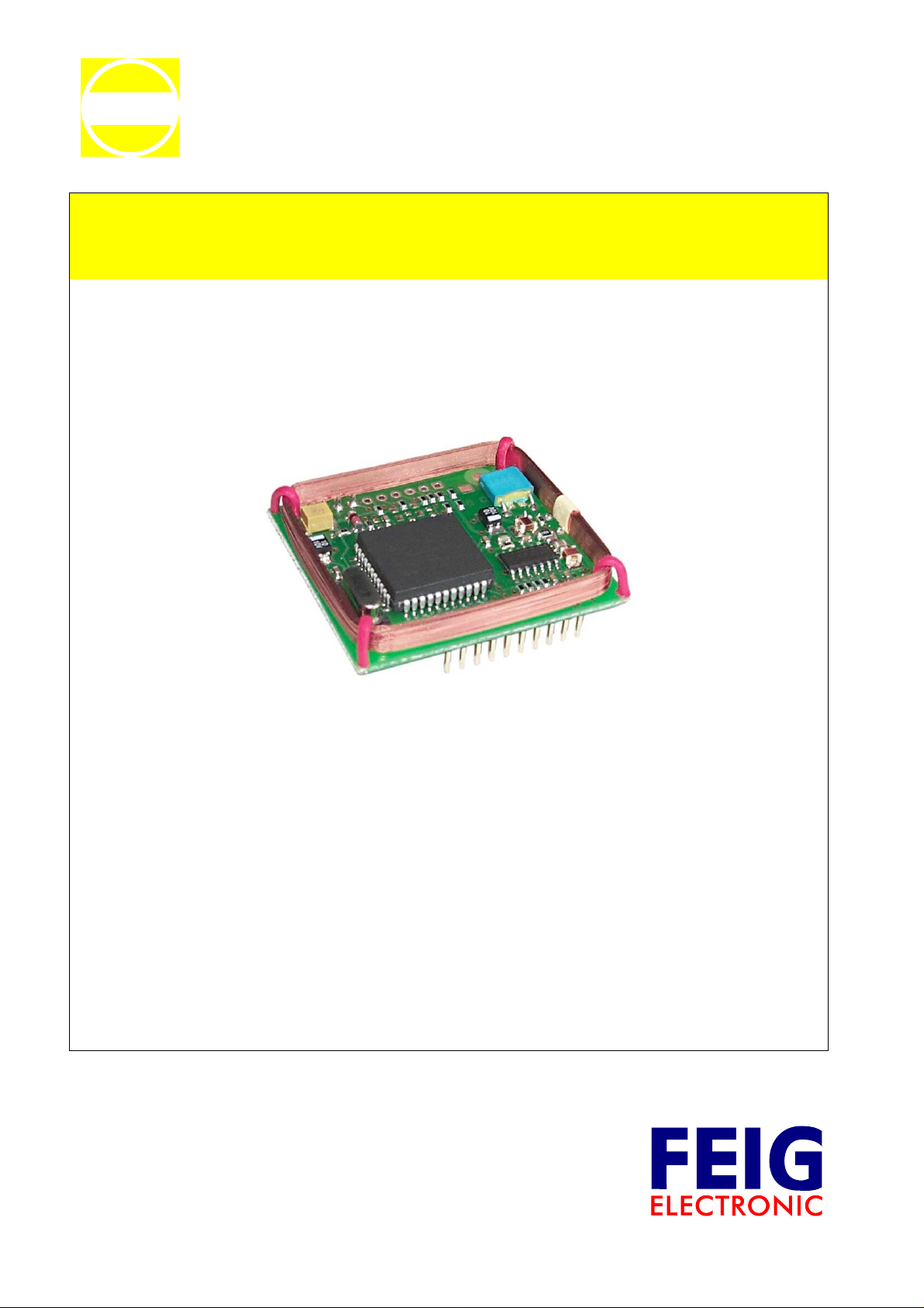
1.2. The OBID® ID RW01L.AB-A
The OBID® ID RW01L.AB-A reader is designed for typical applications involving personnel
identification, access control, time tracking, billing systems, etc.
It features multi-tag capability. This means it can:
• read read-only data carriers (OBID® ID CTx.A)
e.g. H4001, H4002, H4022, H4102, etc. from EM Microelectronics and
Unique from SOKYMAT as well as
• read/write transponders (OBID
HITAG 1 and HITAG S from Philips Semiconductors.
The reader has a bi-directional, asynchronous interface (RS232-TTL) and a unidirectional data/clock
interface which can run in Wiegand or magnetic card reader emulation. The emulation modes of the
data/clock interface ensures easy conversion from traditional identification readers to the OBID
RW01L.AB-A.
The OBID
The OBID
®
ID RW01L.AB-A can be easily software-configured for any application.
®
ID RW01L.AB-A offers access to the entire physical memory range of the supported
transponders (see: 3.2. [0x14] WRITE_DB (Write data block(s)) / 3.3. [0x15] READ_DB (Read data
block(s)
®
ID DTx.B)
®
ID
FEIG ELECTRONIC GmbH Page 5 of 39 H20801-1e-ID-B.doc

®
OBID
Manual ID RW01L.AB-A
1.3. Technical data
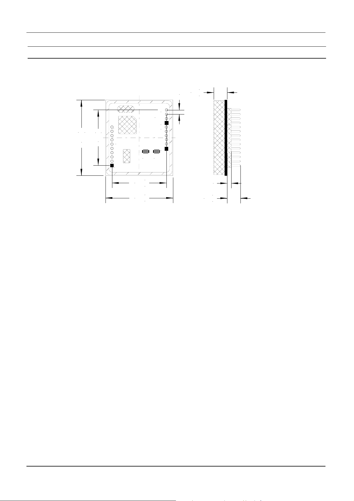
Circuit board dimensions (W x H x D) 45mm x 40mm x 16mm +/- 1mm
Connection 2 x 10-pin connector on the solder side
(pins: 0.7x0.7/ long incl. approx. 8mm insulator
Temperature range (operating and storage) -20°C to +70°C
Supply voltage
Current consumption ca. 40 mA
Operating frequency 125 kHz
Antenna Integrated (mounted on circuit board)
Supported transponders
Reading Range with ISO transponder card
1
Interfaces
Functions
5V DC± 5 %
• read-only:
- ID CTx.A
- H4001, H4002, H4022, H4102,
- Unique
- Q5, e5555 (plain manchester 64 Bit
read-only mode)
• read/write
- ID DTx.B
- Hitag 1
- Hitag S
• ca. 80 mm
• RS232-TTL
• Data / Clock
- Magnetic card emulation
(to (ISO 7811 Track1 or Track2)
- Wiegand Emulation
• Polling mode (over RS232-TTL)
Reading and writing transponder data
• Scan mode (over RS232-TTL and Data / Clock)
Autonomous reading of transponder data
Applicable Norms
European RF Approval EN 300 330
EMC EN 300 683
1
Depending on the antenna size and Q-factor of the antenna in the transponder
FEIG ELECTRONIC GmbH Page 6 of 39 H20801-1e-ID-B.doc
®
OBID
1.4. Dimensions
+0,5
45,0
-0,5
Manual ID RW01L.AB-A
+0,5
8,0
-0,5
2,54
4
X2
B1
X3
1
6
1
2,5
+0,5
8,0
-0,5
10
-0,1
+0,1
X1
33,0
B2
1
+0,1
32,4
-0,1
+0,5
40,0
-0,5
Fig. 1: Dimensions (mm)
FEIG ELECTRONIC GmbH Page 7 of 39 H20801-1e-ID-B.doc

®
OBID
Manual ID RW01L.AB-A
1.5. Pin configuration
Terminal Pin Name Function
1 /CLS Data/clock interface: valid data
X1
X2
X3
2ANT1
3ANT2
4 NC - Not connected 5 /RCP Data/clock interface: clock output
6 /RDP Data/clock interface: data output
7 TxD RS232-TTL TxD
8 RxD RS232-TTL RxD
9 NC - Not connected -
10 NC - Not connected -
1/RST
2 NC. - Not connected 3 GND Ground (0 V)
4 VCC Supply voltage (+5V)
1MOD1
2 NC - Not connected 3 NC - Not connected 4 NC - Not connected 5 NC - Not connected 6 NC - Not connected -
External antenna
Reset input (active to GND ⇒ Reset)
Toggling Polling-Mode / Scan-Mode
MOD1 = open ⇒ Polling-Mode
MOD1 = closed (GND) ⇒ Scan-Mode
1.6. Toggling Polling- / Scan-Mode
There are two ways to toggle between polling and scan mode.
• By soldering a 0 Ω resistor in B1 (see: 1.3. Technical data) scan mode is permanently activated.
• To temporarily activate scan mode, you can tie input MOD1 to potential GND (X2 / Pin 3).
The following table shows the possible configurations.
B1 MOD1
Scan-Mode
Polling-Mode Open Open
FEIG ELECTRONIC GmbH Page 8 of 39 H20801-1e-ID-B.doc
Closed X
Open GND

®
OBID
Manual ID RW01L.AB-A
1.7. Connecting an external antenna
In place of the antenna on the ID RW01L.AB-A, you may connect an external antenna to terminals
ANT1 and ANT2 (X1). When connecting an external antenna, you must separate the two connections
on the onboard antenna.
Note the following when dimensioning and tuning the antenna.
Antenna parameters
- Recommended max. dimensions 70 x 70 mm
- Antenna coil material : Lacquered copper wire
- Antenna coil wire thickness: 0.2 mm
- Inductance: 737 ± 7 µH
- Resistance: 10 ± 1 Ω
- Intrinsic capacitance < 120 pF
Test points:
ANT2 Antenna signal:
GND Reference potential
Fig. 2: Antenna signal between ANT2 and GND
Test values
Upp: 10 V
f: 125 kHz
NOTE:
The reader is designed for operating only one antenna. Operating 2 parallel switched antennas
may damage the reader, or at least have a negative impact on the read range of the reader.
FEIG ELECTRONIC GmbH Page 9 of 39 H20801-1e-ID-B.doc
®
OBID
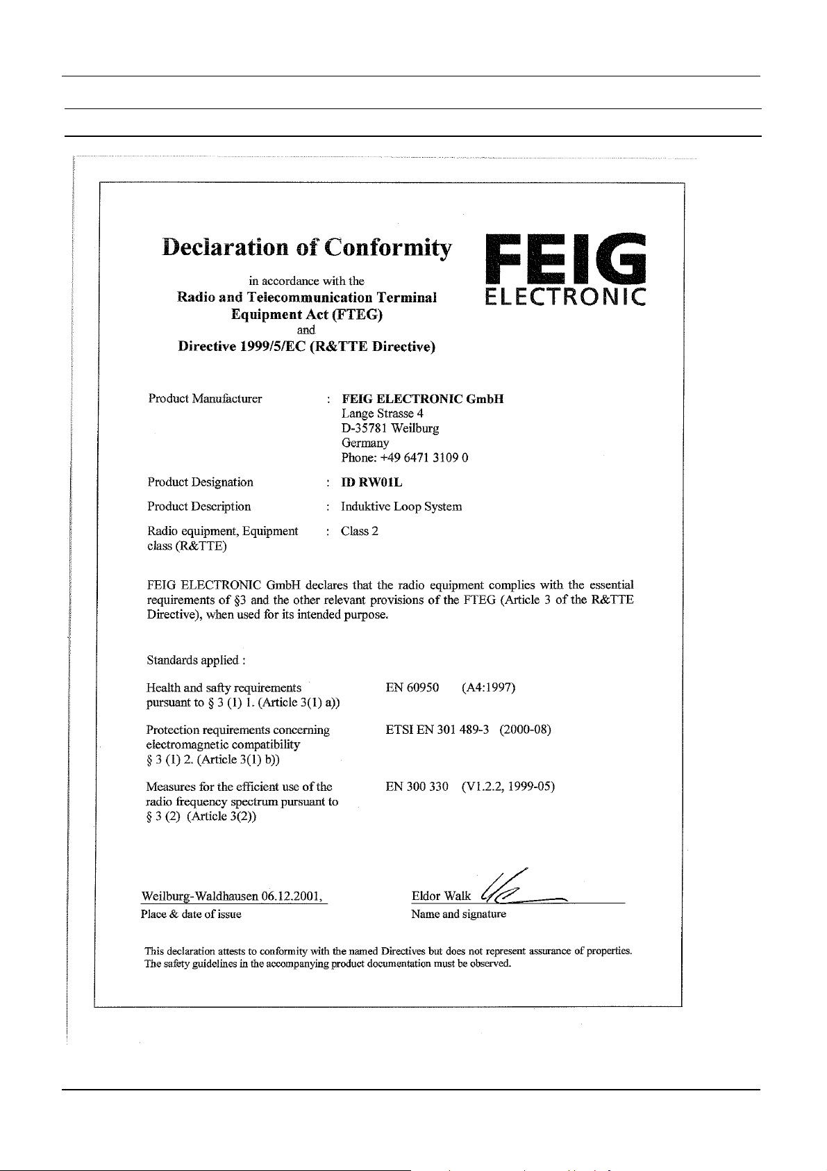
1.8. Declaration of Conformity
Manual ID RW01L.AB-A
FEIG ELECTRONIC GmbH Page 10 of 39 H20801-1e-ID-B.doc

®
OBID
Manual ID RW01L.AB-A
2. Data traffic between Reader and Host
There are three different kinds of data traffic between the reader and a host (terminal, PC, etc.).
Polling and scan modes are used for data exchange between the transponder and host, whereas
configuration mode is used to configure the reader parameters to the particular application. Which kind
of data traffic is supported by which interface is shown in the table below.
Polling-Mode
Scan-Mode
Configuration-Mode
Asynchronous interface
(RS232-TTL)
z
zz
z
Data- / Clock interface
-
-
NOTES:
• A hardware solution is used for toggling between polling and scan mode (see: 1.6. Toggling
Polling- / Scan-Mode)
• When scan mode is active, neither polling nor configuration mode is allowed!
FEIG ELECTRONIC GmbH Page 11 of 39 H20801-1e-ID-B.doc

®
OBID
Manual ID RW01L.AB-A
2.1. Asynchronous interface, data formats and protocol frames
The asynchronous interface can be used to configure the ID RW01L.AB-A, write data to the
transponder and read data from the transponder. Communication between reader and host (terminal,
PC, etc.) takes place using fixed protocols. The protocol used is designed for data bus exchange and
includes a bus address.
In data traffic over the asynchronous interface the reader replies with the requested data and a status
message. The reply always includes the sent control byte.
Protocol structure:
Host → Reader:
1 2 3 4...n-1 n
Length = n COM-Adr Control byte Protocol data CSUM
Host ← Reader
1 2 3 4 (5...n-1) n
Length = n COM-Adr Control byte
Status
1
(protocol data) CSUM
Length n:
Number of protocol bytes 1- n incl. length byte and checksum
COM-Adr:
0..7 Device address for bus operation
NOTE(S):
The reader can always be accessed at COM-Adr = 255.
Status / protocol data:
Contains the status message or protocol data to or from reader
CSUM:
XOR operation of the protocol byte from 1 to n-1
1
see APPENDIX B:
FEIG ELECTRONIC GmbH Page 12 of 39 H20801-1e-ID-B.doc
 Loading...