


INSTALLATION
final – public (B)
2014-11-24 – M30117-1e-ID-B
ID ISC.ANT.U270/270-FCC
Standard UHF Antenna

OBID i-scan
®
UHF
Installation
ID ISC.ANT.U270/270-FCC
FEIG ELECTRONIC GmbH Page 2 of 16 M30117-1e-ID-B
Note
Copyright 2014 by
FEIG ELECTRONIC GmbH
Lange Strasse 4
D-35781 Weilburg
Tel.: +49 6471 3109-0
http://www.feig.de
With the edition of this document, all previous editions become void. Indications made in this manual may be
changed without previous notice.
Copying of this document, and giving it to others and the use or communication of the contents thereof are
forbidden without express authority. Offenders are liable to the payment of damages. All rights are reserved
in the event of the grant of a patent or the registration of a utility model or design.
Composition of the inform ation in this docum ent has been done to the best of our knowledge. FEIG
ELECTRONIC GmbH does not guarantee the correctness and completeness of the details given in this
manual and may not be held liable for damages ensuing from incorrect or incomplete information. Since,
despite all our efforts, errors may not be completely avoided, we are always grateful for your useful tips.
The instructions given in this manual are based on advantageous boundary conditions. FEIG ELECTRONIC
GmbH does not give any guarantee promise for perfect function in cross environments and does not give
any guaranty for the functionality of the complete system which incorporates the subject of this document.
FEIG ELECTRONIC call explicit attention that devices which are subject of this document are not designed
with components and testing methods for a level of reliability suitable for use in or in connection with surgical
implants or as critical components in any life support systems whose failure to perform can reasonably be
expected to cause significant injury to a human. To avoid damage, injury, or death, the user or application
designer must take reasonably prudent steps to protect against system failures.
Use Exclusion in Transportation Market: Devices which are subject of this document may NOT be sold,
used, leased, offer for sale, or otherwise transferred, exported, and imported by anyone in the Transportation
Market. “Transportation Market” means (i) Electronic Toll and Traffic Management (ETTM), (ii) Public Sector
Vehicle Registration, Inspec tion and Licensing Programs, (iii) Railroad Locomotive and Wagon tracking, (iv)
airport based ground transportation management systems (GTMS) and taxi dispatch, (v) revenue based
parking, and (vi) vehicle initiated mobile payment applications, where the RFID sticker/tag is initially attached
to the vehicle but not incorporated at the point of vehicle manufacture.
FEIG ELECTRONIC GmbH assumes no responsibility for the use of any information contained in this document and makes no representation that they free of patent infringement. FEIG ELECTRONIC GmbH does
not convey any license under its patent rights nor the rights of others.
OBID
®
and OBID i-scan® are registered trademarks of FEIG ELECTRONIC GmbH.

OBID i-scan
®
UHF
Installation
ID ISC.ANT.U270/270-FCC
FEIG ELECTRONIC GmbH Page 3 of 16 M30117-1e-ID-B
General information's re gar ding this document
• The sign "" indicates extensions or changes of this manual compared with the former issue.
• If bits within one byte are filled with "-", these bit spaces are reserved for future extensions or
for internal testing- and manufacturing-functions. These bit spaces must not be changed, as this
may cause faulty operation of the reader.
• The following figure formats are used:
0...9: for decimal figures
0x00...0xFF: for hexadecimal figures,
b0...1 for binary figures.
• The hexadecimal value in brackets "[ ]" marks a control byte (command).

OBID i-scan
®
UHF
Installation
ID ISC.ANT.U270/270-FCC
FEIG ELECTRONIC GmbH Page 4 of 16 M30117-1e-ID-B
Contents
1. Safety Instructions / Warning - Read before start-up ! 5
2. Performance Features of the Antenna ANT.U270/270-FCC 6
3. Installation 7
3.1. Mounting Holes.................................................................................................................. 7
3.2. Installation with Mounting Set .......................................................................................... 8
3.3. Draining Holes ................................................................................................................... 9
3.4. Membrane for pressure balance ..................................................................................... 10
3.5. Antenna cable .................................................................................................................. 11
4. VSWR 12
5. Antenna Pattern 13
6. Technical Data 15

OBID i-scan
®
UHF
Installation
ID ISC.ANT.U270/270-FCC
FEIG ELECTRONIC GmbH Page 5 of 16 M30117-1e-ID-B
1. Safety Instructions / Warning - Read before start-up !
• The device may only be used for the intended purpose designed by for the manufacturer.
• The operation manual should be conveniently kept available at all times for each user.
• Unauthorized changes and the use of spare parts and additional devices which have not been
sold or recommended by the manufacturer may cause fire, electric shocks or injuries. Such
unauthorized measures shall exclude any liability by the manufacturer.
• The liability-prescriptions of the manufacturer in the issue valid at the time of purchase are valid
for the device. The manufacturer shall not be held legally responsible for inaccuracies, errors,
or omissions in the manual or automatically set parameters for a device or for an incorrect
application of a device.
• Repairs may only be executed by the manufacturer.
• Installation, operation, and maintenance procedures should only be carried out by qualified
personnel.
• Use of the device and its installation must be in accordance with national legal requirements
and local electrical codes .
• When working on devices the valid safety regulations must be observed.
• Special advice for carriers of cardiac pacemakers:
Although this device doesn't exceed the valid limits for electromagnetic fields you should keep
a minimum distance of 25 cm between the device and your cardiac pacemaker and not stay in
an immediate proximity of the device respective the antenna for some time.

OBID i-scan
®
UHF
Installation
ID ISC.ANT.U270/270-FCC
FEIG ELECTRONIC GmbH Page 6 of 16 M30117-1e-ID-B
2. Performance Features of the Antenna ANT.U270/270-FCC
The antenna ID ISC.ANT.U270/270 Type –FCC is a circular polarized antenna and can be used at
operating frequencies in the UHF range from 902 MHz – 928MHz.
Due to the circular polarization a reading of Transponder in two orientations is possible.
The antenna is optimized for RFID applications under FCC within the UHF frequency band. In this
frequency band the antenna offers best possible reading performance.
.
Table 1: Ordering Information - Antenna
Description Type Frequency Order number
Antenna ID ISC.ANT.U270/270 -FCC 902 MHz – 928 MHz 3686.000.00

OBID i-scan
®
UHF
Installation
ID ISC.ANT.U270/270-FCC
FEIG ELECTRONIC GmbH Page 7 of 16 M30117-1e-ID-B
3. Installation
3.1. Mounting Holes
The antenna is designed for wall or fixture mounting. Mounting holes are provided in the housing.
Please note that only these holes should be used when mounting the antenna. An optional mounting set is available to simplify the attachment of the antenna to portal structures or poles and can
be ordered from FEIG ELECTRONIC GmbH.
NOTE:
When fastening the screws it must be ensured that the housing of the antenna is not bend.
Optionally the attachment points should be supported by suitable washers or spacers
(Height 14 mm).
If mounted outside the preferred mounting direction of the antenna is vertical with the connection cable towards ground.
Never mount the antenna in a way that the connection cable is guided to the top.
Figure 1: Mounting Drawing
CAUTION:
Bending radius of the connection cable: 15 mm (static) / 30 mm (dynamic)
230,5
230,5
273
212
273
37
57,5
Ø5,5

OBID i-scan
®
UHF
Installation
ID ISC.ANT.U270/270-FCC
FEIG ELECTRONIC GmbH Page 8 of 16 M30117-1e-ID-B
3.2. Installation with Mounting Set
A special mounting set provides an easy method of mounting of the antenna at a portal, mast, pole
or bar. After mounting, the antenna can be changed and positioned at three orientations.
Figure 2: Mounting Set with Antenna
Table 2: Ordering Information - Mounting Set
Description Order number
ID ISC.ANT.U270/270-MS Mounting Set Antenna UHF 3309.000.00.00

OBID i-scan
®
UHF
Installation
ID ISC.ANT.U270/270-FCC
FEIG ELECTRONIC GmbH Page 9 of 16 M30117-1e-ID-B
3.3. Draining Holes
There are two draining holes inside the housing at the bottom left- and right corner of the antenna.
These holes are used to guide condensing water out of the outer circle of the housing.
NOTE:
The protection class of the antenna is not affected by the draining holes. The blocking that
guarantees the protection class of IP65 is inside the housing.
Water in the outer circle of the housing does not have any impact on the performance of the
antenna.
Figure 3: Draining holes at the bottom left- and right corner of the antenna

OBID i-scan
®
UHF
Installation
ID ISC.ANT.U270/270-FCC
FEIG ELECTRONIC GmbH Page 10 of 16 M30117-1e-ID-B
3.4. Membrane for pressure balance
At the back of the antenna there is a small hole covered with a thin membrane that is used for
pressure balance between the air inside the housing and the air outside the housing. The membrane is water resistant and does not influence the protection class of the antenna.
Figure 4: Membrane for pressure balance
CAUTION:
To keep the full protection class and to prevent performance losses of the antenna it needs
to be ensured that the membrane is not damaged.

OBID i-scan
®
UHF
Installation
ID ISC.ANT.U270/270-FCC
FEIG ELECTRONIC GmbH Page 11 of 16 M30117-1e-ID-B
3.5. Antenna cable
There are two antenna cable assemblies available for the extension of the antenna cable. These
cable assembly can be ordered by FEIG ELECTRONIC GmbH in a two meter (2 m) or six meter
(6 m) version.
Table 3: Ordering Information - Antenna Cable
Length Description Order number
2 meter ID ISC.ANT.C2-A UHF Antenna Cable 2m 1654.002.00.00
6 meter ID ISC.ANT.C6-A UHF Antenna Cable 6m 1654.003.00.00
Note:
The maximum tightening torque of the SMA jack is 0,45 Nm (4.0 lbf in).

OBID i-scan
®
UHF
Installation
ID ISC.ANT.U270/270-FCC
FEIG ELECTRONIC GmbH Page 12 of 16 M30117-1e-ID-B
4. VSWR
Figure 5: Typical VSWR of the antenna ID ISC.ANT.U270/270-FCC

OBID i-scan
®
UHF
Installation
ID ISC.ANT.U270/270-FCC
FEIG ELECTRONIC GmbH Page 13 of 16 M30117-1e-ID-B
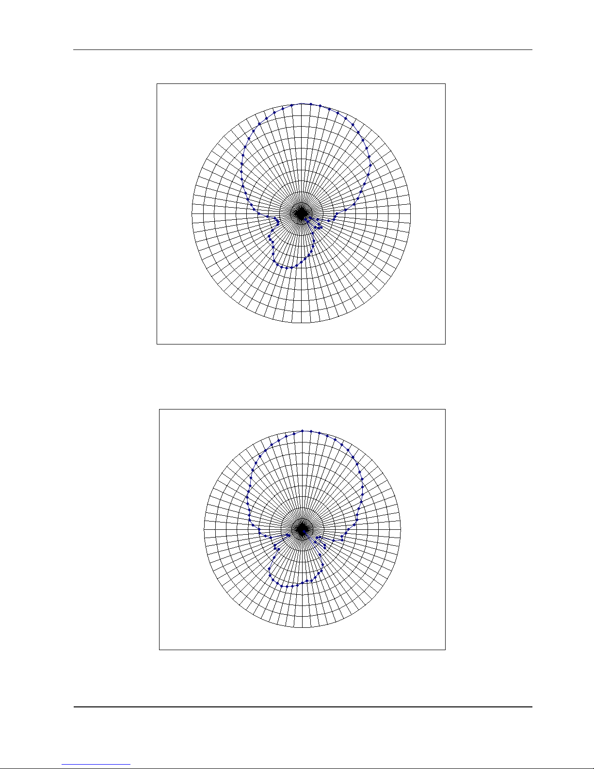
5. Antenna Pattern
The 3 dB Beamwidth of the antenna is 65° x 65°.
Figure 6: 3 dB Beamwidth
65°
65°
OBID i-scan
®
UHF
Installation
ID ISC.ANT.U270/270-FCC
FEIG ELECTRONIC GmbH Page 14 of 16 M30117-1e-ID-B
Figure 7: Typical antenna pattern of the Antenna ID ISC.ANT.U270/270-FCC horizontal
Figure 8: Typical antenna pattern of the Antenna ID ISC.ANT.U270/270-FCC vertical
-23
-20
-17
-14
-11
-8
-5
-2
1
4
7
0
5
10
15
20
25
30
35
40
45
50
55
60
65
70
75
80
85
90
95
100
105
110
115
120
125
130
135
140
145
150
155
160
165
170
175
180
185
190
195
200
205
210
215
220
225
230
235
240
245
250
255
260
265
270
275
280
285
290
295
300
305
310
315
320
325
330
335
340
345
350
355
-22
-19
-16
-13
-10
-7
-4
-1
2
5
0
5
10
15
20
25
30
35
40
45
50
55
60
65
70
75
80
85
90
95
100
105
110
115
120
125
130
135
140
145
150
155
160
165
170
175
180
185
190
195
200
205
210
215
220
225
230
235
240
245
250
255
260
265
270
275
280
285
290
295
300
305
310
315
320
325
330
335
340
345
350
355

OBID i-scan
®
UHF
Installation
ID ISC.ANT.U270/270-FCC
FEIG ELECTRONIC GmbH Page 15 of 16 M30117-1e-ID-B
6. Technical Data
MECHANICAL DATA
Housing Plastic ASA/ABS
Dimension (W x H x D) 273 mm x 273 mm x 58 mm
Weight approx. 1210 g
Protection Class IP 65
Color White
ELECTRICAL DATA
Operating Frequency 902 MHz to 928 MHz
Gain, typ. 9,0 dBic
3 dB Beamwidth
• E-Plane
• H-Plane
65°
65°
Polarization Circular
VSWR < 1,3:1
Antenna Connector
SMA socket (50 Ω)
AMBIENT CONDITIONS
Temperature Range
• Operation
• Storage
-25 °C to +55 °C
-25 °C to +80 °C

OBID i-scan
®
UHF
Installation
ID ISC.ANT.U270/270-FCC
FEIG ELECTRONIC GmbH Page 16 of 16 M30117-1e-ID-B
MECHANICAL DATA MOUNTING SET
Material Aluminum, steel zinc-plate
Clamping zone for circular profiles 30 mm to 60 mm
Weight approx. 400 g
Alignment of the antenna Adjustable at three orientations
 Loading...