

Installation Instructions
Input Port
PoE ILS
Assembly Components:
- PoE ILS assembly – 1 each
- #8-32 X 3/8 “ screw – 4 each
- Installation instructions – 1 each
If any of these items are missing, contact your Oberon representative.
Find a flat work surface to assemble the ceiling enclosure, PoE ILS, access point and antenna(s) prior to mounting in ceiling.
Step 1 - The PoE ILS is designed to be used with Oberon enclosures. At the time of this writing, the only enclosure that
accommodates the PoE ILS is the Oberon Model 1052-00.
Step 2 – Install the PoE ILS board into the 1052-00
with the four supplied screws. Mount the PoE ILS such
that the switch is facing outward toward the door, as
shown in Figure 1.
Step 3 – Route the incoming Ethernet cable through
the 1052-00 following the instructions provided with
the enclosure, and insert the RJ-45 connector into the
IN port on the PoE ILS. The port locations are shown
in Figure 2.
Step 4 – Route the incoming Ethernet cable through
the 1052-00 following the instructions provided with
the enclosure, and insert the RJ-45 connector into the
Figure 1 - Hardware installation.
Page 2
Rev. 02/12/13 P/N 1790 Oberon, Inc. •••• 1315 South Allen Street •••• State College, PA 16801 Copyright 2013
IN port on the PoE ILS. The port locations are shown
in Figure 2.
(877) 867-2312 • www.oberonwireless.com
Step 4 – If desired, during WAP testing or maintenance, to provide power to the WAP with the enclosure door open a PC
jumper (customer provided) can be used on the two pin jumper located beside the switch on the PoE ILS board. Ensure
that the jumper is not left in place during normal operation, or the PoE ILS will be bypassed.
Page 3
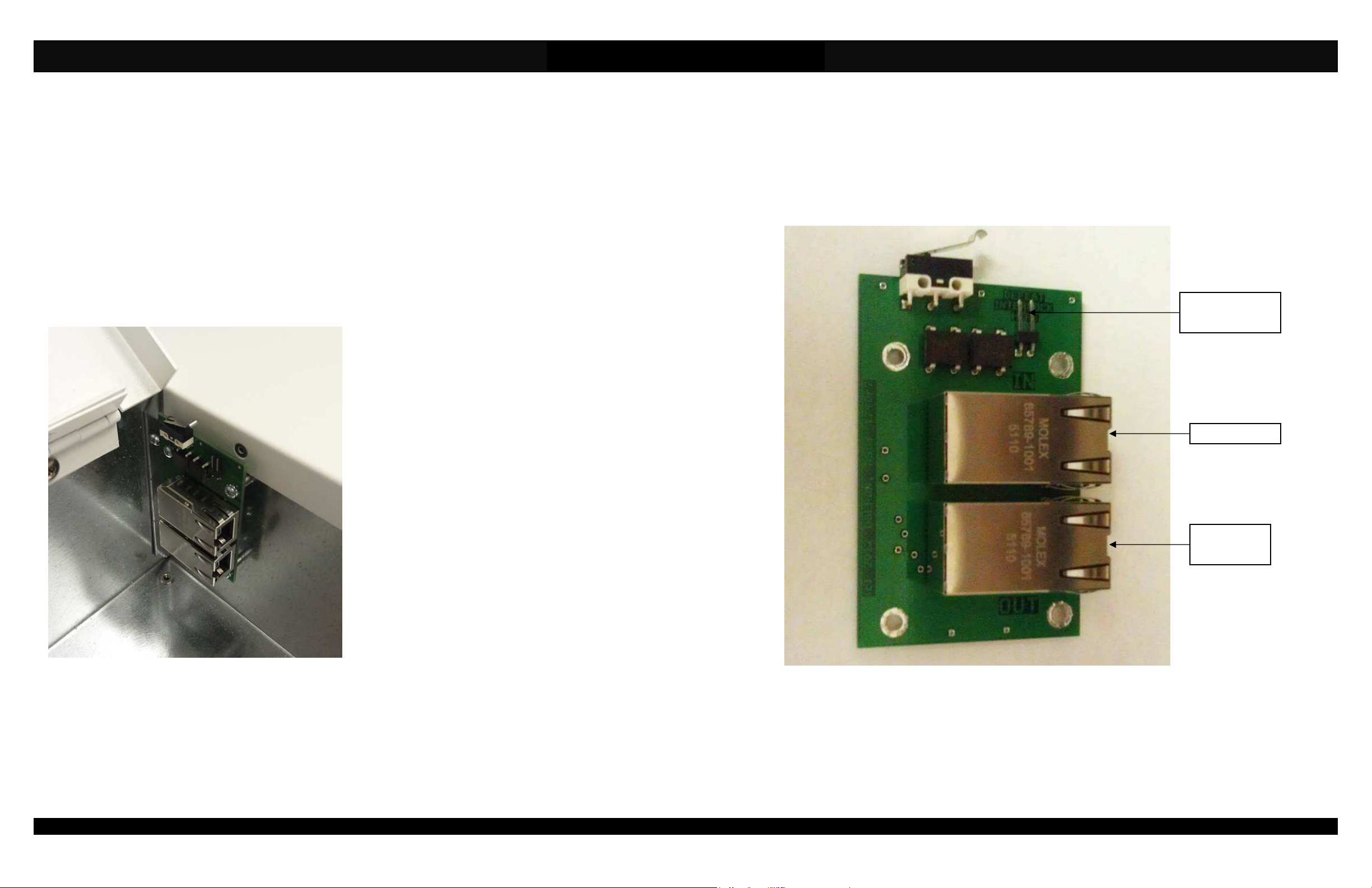
Figure 2
Optional Bypass
Jumper Pins
Output Port
To WAP

Page 4
PoE ILS
Installation Instructions
**** WARNING ****
Please thoroughly read the product warning below
-
before installation to provide for a safe work
environment.
1. Ceiling mounted products should be installed in accordance with National Electric Code paragraphs 300.10 (Electrical
Continuity of Metal Raceways and Enclosures) and 300.11 (Securing and Supporting). Independent support wires or
other means must be used for the installation of this product in the ceiling. Acoustical, suspended, false, drop and
concealed spline ceiling grid work is not designed to support the weight of this product. Oberon’s ceiling mounted
products have four support wire tabs on the back box. These tabs shall be used for supporting the product with
independent support wires, wire rope, threaded rod, or other secure support means of adequate gauge and fire
resistance.
2. When closing the enclosure access door, be sure that the cam lock is completely engaged to prevent the access door
from accidentally swinging open.
3. When opening the enclosure door, be sure to support the door to prevent the door from accidentally falling open.
4. This enclosure has a maximum operating ambient of 55º C (131º F), the temperature within the enclosure may not
exceed this temperature, depending on power dissipation within enclosure.
5. A minimum air clearance of 1“ between the housing of the access point and the enclosure side walls must be
maintained for the safe operation of the equipment.
6. This product is intended to be installed by trained personnel.
7. Only Listed ITE shall be installed within the enclosure.
8. This product is to be repaired by personnel trained by the manufacturer or returned to the manufacturer for repair or
replacement.
9. Maximum weight to be installed in the unit is 25 lbs.
10. All knockouts, openings, and holes shall be sealed with a plug constructed of metal, or a non-metal material that
complies with UL 2043 or UL 1479.
11. All unused mounting holes should be sealed with tape or other material that complies with UL 1479.
12. If AC power is used inside the enclosure, connect the ground wire to the green ground screw located near the
knockout in the backbox.
Page 1
 Loading...