

Installation Instructions
Model Number 1075-AP225
Assembly Components:
- Ceiling enclosure Model 1075-AP225 assembly – 1 each
- Ceiling tile bridge – 2 each
- #8-32 X 1/4 “ screw –4 each
- #8-32 nut – 4 each
- 3/4” Trade Size Cable Clamp – 1 each
- Keys for access door lock – 2 each
- Support wire – 4 each
- Fire Block Foam – 1 each
If any of these items are missing, contact your Oberon representative.
Find a flat work surface to assemble the ceiling enclosure, access point and antenna(s) prior to mounting in ceiling.
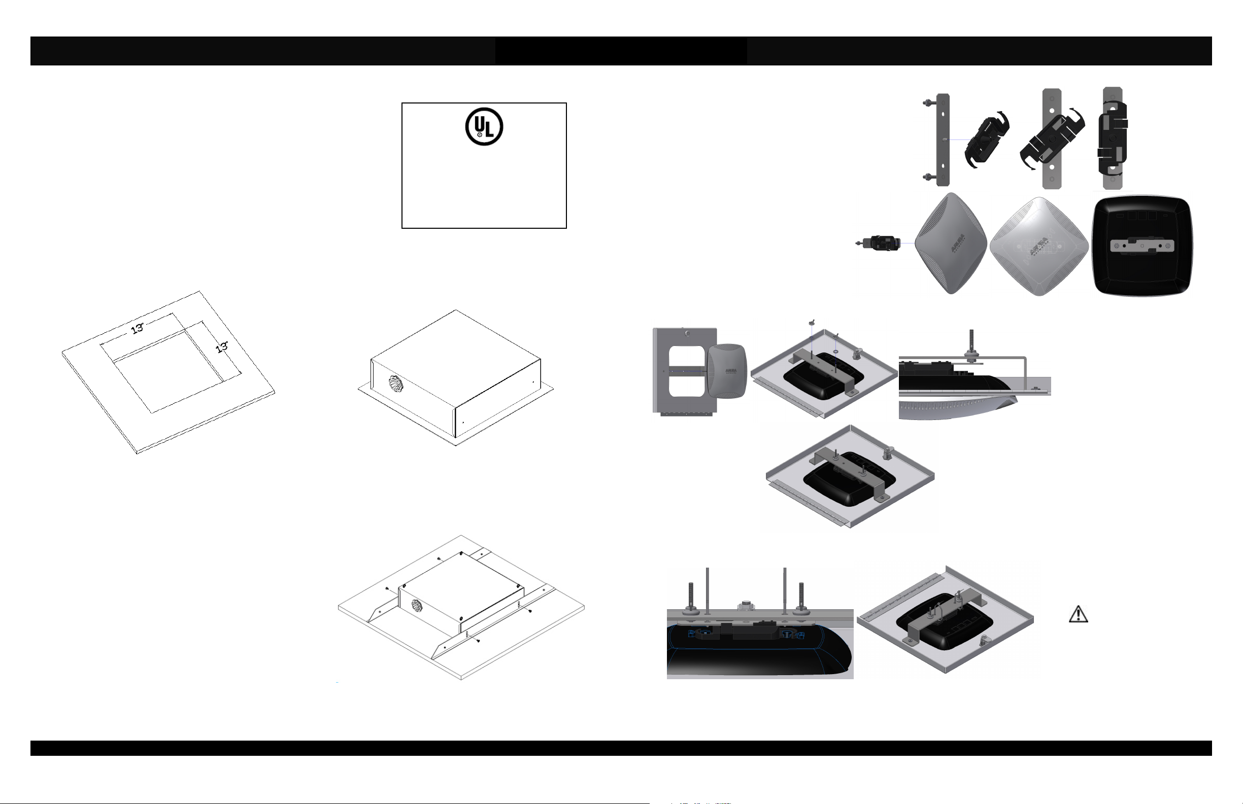
Step 1 - Cut a 13” x 13” opening in the center of a ceiling tile (not included – ref. Figure 1).
Figure 1 - Cutting ceiling tile.
Step 2 – Place the ceiling enclosure assembly on the work surface. Remove one of the 1” trade size hole cover on the side of
the enclosure and install the 1” conduit nipple (the side on which the conduit nipple is to be installed will be determined by the
location the enclosure is to be installed and direction from which conduit will be brought into the enclosure – ref. Figure 2).
Step 3 –Lay ceiling tile over the enclosure assembly such that
the previously cut opening in the ceiling tile is equally spaced
around the outside of the enclosure (ref. Figure 3). Place the
ceiling tile bridges along each side of the enclosure and attach
using a #8-32 screw. Prior to tightening, be sure to properly
align the tile bridges so the ends of the tile bridges align with
the outside edge of the ceiling tile. Once the tile bridges are
properly aligned, press the shoulder of the tile bridge down
firmly against the tile and then securely tighten the screws.
This is to assure that there is minimal gap between the
enclosure’s flange and the ceiling tile once it is placed in the
ceiling. The four (4) holes on the tile bridge will be used to
secure the enclosure with grid wires.
Page 2
This product is Listed by Underwriters
Laboratories Inc. Representative
samples of this product have been
evaluated by UL and meet applicable
safety standards.
File #E348543
Figure 2 - Hardware installation.
Figure 3 - Installation to ceiling tile.
Step 4 – Snap Aruba Networks t-bar clip
onto the t-bar mount by angling at a 45°
angle and twisting the clip until it snaps in
place. Next, attach the access point to the
Aruba Networks t-bar clip by angling the
access point at a 45° angle and twisting it
until it also snaps in place (Figure 4).
Step 5 – Align the threaded studs to the
two outer holes in the bracket attached to
the door. Once the access point is snug in
the hole, place the lock washer and wing
nut onto the threaded rod. Tighten wing
nuts until they are snug. With your fingers,
tighten the hex nuts on the underside of
the bracket then re-tighten the wing nuts
until they no longer move freely (Figure 5).
Figure 5 - Fasten T-Bar Bracket.
Figure 6 - Wire Tie Install.
Page 3
Figure 4 - T-Bar Clip Install.
Step 6 – For added security,
attach wire ties to the two
inner holes of the bracket and
the t-bar mount. Make sure
securely fasten the wire ties in
place (Figure 6).
Step 7 – Remove the ceiling
tile and replace it with the
completed access point
enclosure assembly.
**IMPORTANT** - This is
an important safety feature
that could prevent human
injury or damage to the
access point should the
unit become dislodged from
the ceiling.
(877) 867-2312 • www.oberonwireless.com
Rev. A1 03/28/14 Oberon, Inc. •••• 1315 South Allen Street •••• State College, PA 16801 Copyright 2012
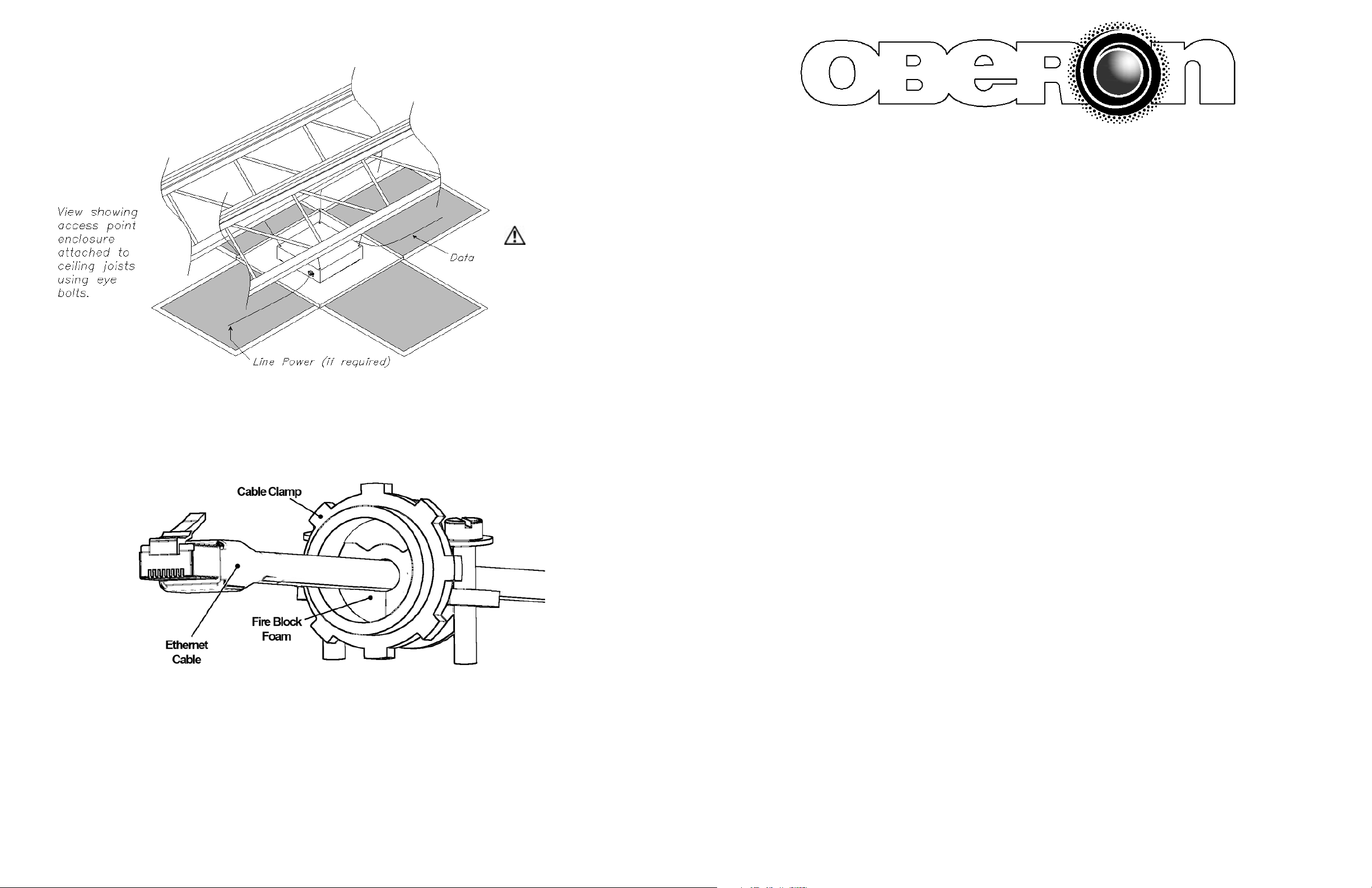
Step 8 – Use minimum 12gauge support wire (included) to
support the access point
enclosure independently of the
ceiling grid. Attach one end of
the wire to the support wire tabs
located along the edge of the
back box and the other end to a
permanent supporting structure
within the ceiling such as a
ceiling joist (Figure 7).
MODEL 1075-AP225
Installation Instructions
**IMPORTANT** - This is
an important safety feature
that could prevent human
injury or damage to the
access point should the unit
become dislodged from the
ceiling grid work.
Figure 7 - Ceiling installation.
Step 9 – Once the assembly has been installed in the ceiling and secured using grid wire, open the door and run the Ethernet
cable into the enclosure through the conduit nipple located on the side of the access point enclosure and attach to the access
point prior to installing on mounting plate.
Insert foam into the conduit connector and pull the data cable through far enough to allow attachment to the access point (8" -
10"). Tighten cable clamp around foam fire block so that there are no air gaps. Be careful not to over tighten and crush the
Ethernet cable(s).
Page 4
**** WARNING ****
Please thoroughly read the product warning below
before installation to provide for a safe work
environment.
1. Ceiling mounted products should be installed in accordance with National Electric Code paragraphs 300.10 (Electrical
Continuity of Metal Raceways and Enclosures) and 300.11 (Securing and Supporting). Independent support wires or
other means must be used for the installation of this product in the ceiling. Acoustical, suspended, false, drop and
concealed spline ceiling grid work is not designed to support the weight of this product. Oberon’s ceiling mounted
products have four support wire tabs on the back box. These tabs shall be used for supporting the product with
independent support wires, wire rope, threaded rod, or other secure support means of adequate gauge and fire
resistance.
2. When closing the enclosure access door, be sure that the cam lock is completely engaged to prevent the access door
from accidentally swinging open.
3. When opening the enclosure door, be sure to support the door to prevent the door from accidentally falling open.
4. This enclosure has a maximum operating ambient of 55º C (131º F), the temperature within the enclosure may not
exceed this temperature, depending on power dissipation within enclosure.
5. A minimum air clearance of 1“ between the housing of the access point and the enclosure side walls must be
maintained for the safe operation of the equipment.
6. This product is intended to be installed by trained personnel.
7. Only Listed ITE products and Listed AC Receptacles shall be installed within the enclosure.
8. This product is to be repaired by personnel trained by the manufacturer or returned to the manufacturer for repair or
replacement.
9. Maximum weight to be installed in the unit is 25 lbs.
10. All knockouts, openings, and holes shall be sealed with a plug constructed of metal, or a non-metal material that
complies with UL 2043 or UL 1479.
11. All unused mounting holes should be sealed with tape or other material that complies with UL 1479.
12. If AC power is used inside the enclosure, connect the ground wire to the green ground screw located near the
knockout in the backbox.
Page 1
 Loading...