

Oberon 1064-00 User Manual
Step 10 –Place the access point in the
opening of the enclosure (reference Figure 5)
with the access points LED light closest to the
key lock. If the key is turned the proper
direction, the access point should drop in and
self-center itself so that the feet on the access
point falls into the key slots on the mounting
plate (reference Figure 5).
MODEL 1064-00
Installation Instructions
NOTE: If the access point and key
slots do not align properly, turn the key
180° and repeat step 5.
Step 11 – After verifying that the access point
is properly seated within the opening, turn the
key 180° to lock the Access Point in place.
The key should require minimal effort to turn. If
excessive force is required to turn the key,
verify that the access point is properly seated
within the opening and then re-try turning the
key.
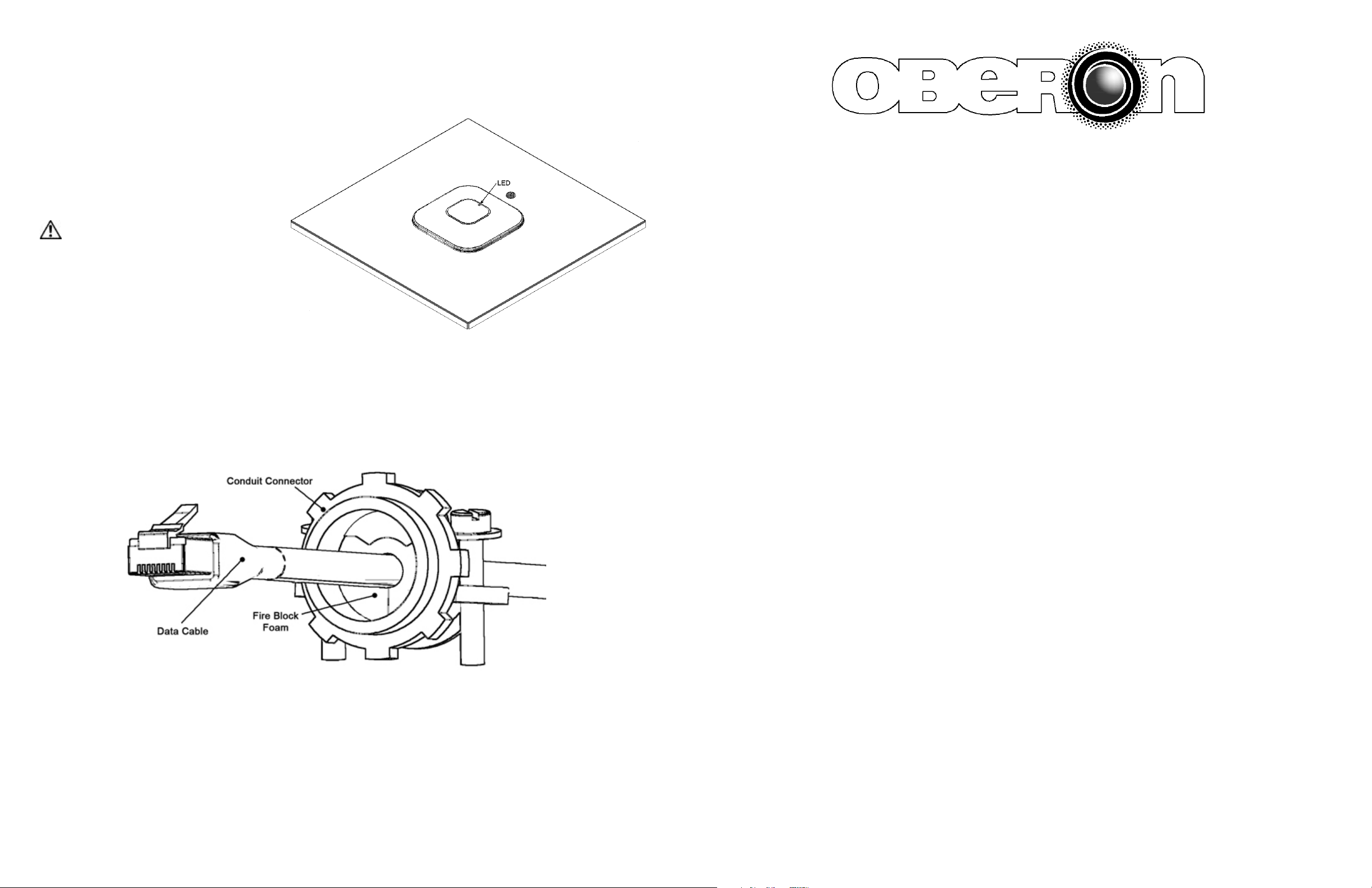
Figure 5 – Proper positioning of AP within the 1064 enclosure. Note
that the access point should be located within the AP mount so that the
LED is located closest to the lock
Figure 6 – Insert foam into the conduit connector and pull the data cable through far enough to allow attachment to the access
point (8" - 10"). Tighten cable clamp around foam fire block so that there are no air gaps. Be careful not to over tighten and
crush the Ethernet cable(s).
Page 4
**** WARNING ****
Please thoroughly read the product warning below
before installation to provide for a safe work
environment.
1. Ceiling mounted products should be installed in accordance with National Electric Code paragraphs 300.10 (Electrical
Continuity of Metal Raceways and Enclosures) and 300.11 (Securing and Supporting). Independent support wires or
other means must be used for the installation of this product in the ceiling. Acoustical, suspended, false, drop and
concealed spline ceiling grid work is not designed to support the weight of this product. Oberon’s ceiling mounted
products have four support wire tabs on the back box. These tabs shall be used for supporting the product with
independent support wires, wire rope, threaded rod, or other secure support means of adequate gauge and fire
resistance.
2. When closing the enclosure access door, be sure that the cam lock is completely engaged to prevent the access door
from accidentally swinging open.
3. When opening the enclosure door, be sure to support the door to prevent the door from accidentally falling open.
4. This enclosure has a maximum operating ambient of 55º C (131º F), the temperature within the enclosure may not
exceed this temperature, depending on power dissipation within enclosure.
5. A minimum air clearance of 1“ between the housing of the access point and the enclosure side walls must be
maintained for the safe operation of the equipment.
6. This product is intended to be installed by trained personnel.
7. Only Listed ITE shall be installed within the enclosure.
8. This product is to be repaired by personnel trained by the manufacturer or returned to the manufacturer for repair or
replacement.
9. Maximum weight to be installed in the unit is 25 lbs.
10. All knockouts, openings, and holes shall be sealed with a plug constructed of metal, or a non-metal material that
complies with UL 2043 or UL 1479.
11. All unused mounting holes should be sealed with tape or other material that complies with UL 1479.
12. If AC power is used inside the enclosure, connect the ground wire to the green ground screw located near the
knockout in the backbox.
Page 1
Installation Instructions
Model Number 1064-00
Assembly Components:
- Ceiling AP mount, Model 1064-00 assembly – 1 each
- #8-32 Screws – 4 each
- #8-32x1/4" Standoffs – 4 each
- Keys for access door lock – 2 each
- 8" Cable tie - 1 each
- Support wire – 4 each
- Firestop Grommet – 1 each
- 1" Conduit Clamp – 1 each
If any of these items are missing, contact your Oberon representative.
Find a flat work surface to assemble the ceiling AP mount and access point prior to mounting in ceiling.
Step 1 – Turn AP mount upside down so that the access point opening is facing toward the table and the connector clamp is
facing upward.
Step 2 – Turn the AP mount over so that
the access point opening is facing
upward. Install the Cisco mounting plate
using four (4) #8-32 pan head screws.
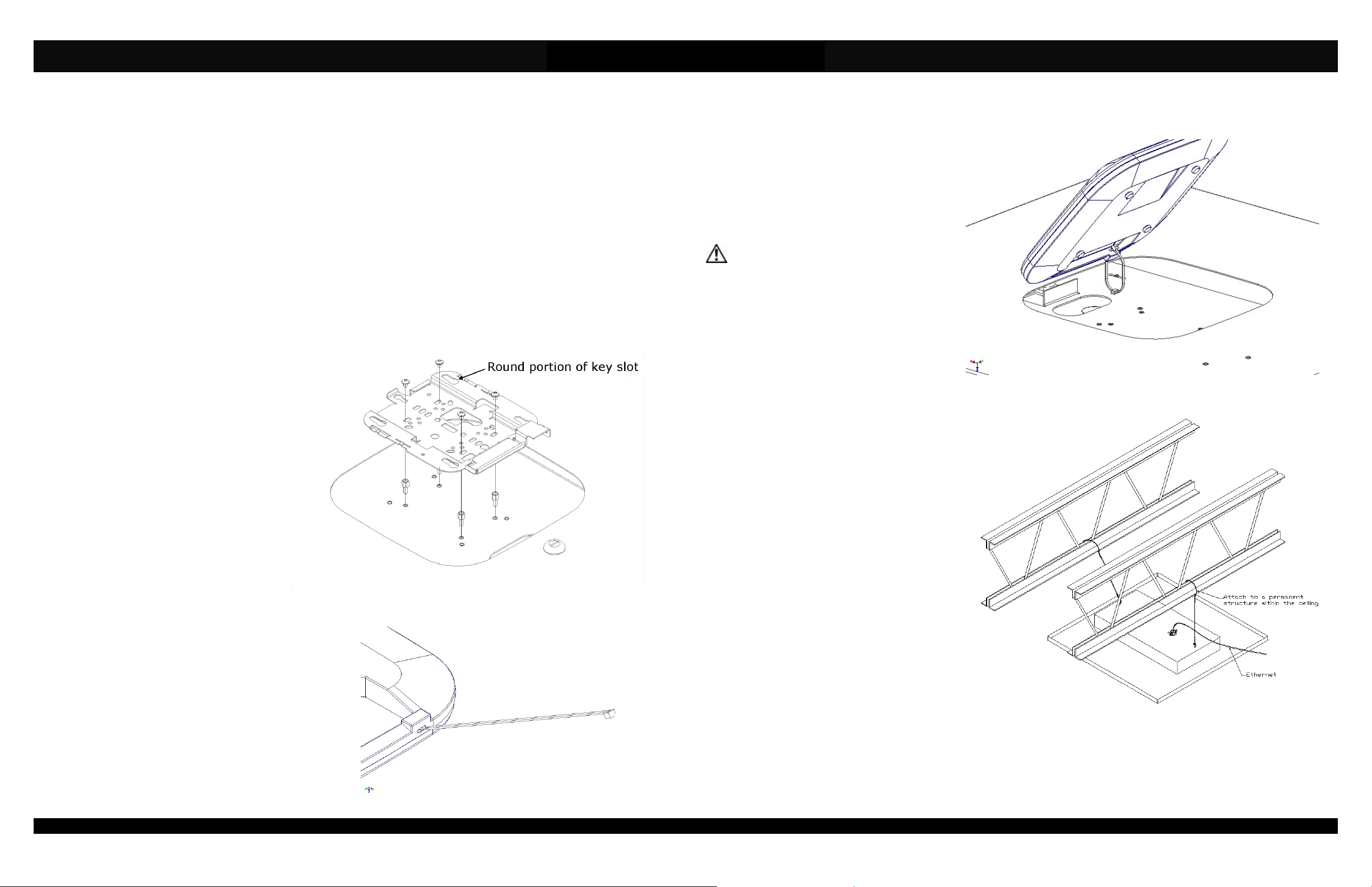
The mounting plate should be placed so
that the round portions of the key slots
are located closest to the enclosure lock
(reference Figure 1). The Cisco
“BRACKET 2” should be used with all
Cisco 1400, 1600, 2600, 3500, 3600 and
3700 Access Points.
NOTE: When using Cisco 3600 and
3700 series access points, mount the
access point mounting plate directly to
the enclosure’s mounting plate. When
using Cisco 1140, 1600, 2600, and 3500
series access points, you will need to
use the optional standoff kit to have
the access point set at the proper
height in the enclosure. The standoff
kit is Oberon P/N 39-STANDOFF.
Step 3 - Optional safety tether: To attach the optional safety
tether, insert the included cable tie into the Kensington lock
slot at an angle toward the top of the access point. There is
an opening that will allow the cable tie to pass through
(reference Figure 2).
Step 4 - Loop the cable tie through the tether anchor located
on the mounting plate of the enclosure and lock the cable tie
loosely (reference Figure 3).
Page 2
Rev. 12 Oberon, Inc. •••• 1315 South Allen Street •••• State College, PA 16801 Copyright 2013
Figure 1 – Close-up showing proper orientation of the Cisco Bracket 2, refer to note
for using standoffs
Figure 2 - Insert cable tie through Kensington lock slot
(877) 867-2312 • www.oberonwireless.com
Step 5 – Remove the ceiling tile and replace it
with the completed AP mount assembly.
Step 6 – Use minimum 12-gauge grid wire to
attach the AP mount to the ceiling. Attach one
end of the wire to the support tabs and the other
end to a permanent structure within the ceiling
such as a ceiling joist.
**IMPORTANT** - This is an important
safety feature that could prevent human
injury or damage to the access point should
the unit become dislodged from the ceiling.
Step 7 – Run the data and power cable (if
required) through the conduit connector located
on the side of the access point enclosure. Pull
the data cable through far enough to allow
attachment to the access point (8" - 10"). Clip
the provided firestop grommet on to the data
and power cable inside the enclosure, and slide
the grommet into the conduit connector so the
end is flush with the connector.
Step 8 – Attach data and power cables to the
access point from the front side of the AP
mount. Make sure the firestop grommet is still
within the conduit connector
Step 9 – Insert the key into the lock and turn the
lock 180° in both directions to determine which
way the slide needs to be moved so that the
mounting plate is located furthest from the key
lock.
NOTE: The Cisco 1140 AP is locked into the AP
mount using the key. The turning of the key
activates a cam mechanism that slides the
mounting plate underneath the access point,
thus, locking the feet of the access point into
keyhole shaped slots located on the mounting
plate. Once the access point is installed and the
key removed, the access point is securely
mounted in the AP mount and cannot be
removed without the key. Additional security
measures as described in Cisco’s Installation
Guide (i.e. padlocks. security screws, and
security hasp) are not required.
Page 3
Figure 3 - Loosely attach the cable tie
Figure 4 - Installation of grid wires and Ethernet cable.
 Loading...