

Assembly Components:
- Ceiling enclosure Model 1059-00 assembly – 1 each
- Keys for access door lock – 2 each
- 1” Trade Size Cable Clamp – 1 each
- Support wire – 4 each
- Firestop Grommet – 1 each
If any of these items are missing, contact your Oberon representative.
Find a flat work surface to
assemble the ceiling enclosure,
access point and antenna(s) prior
to mounting in ceiling.
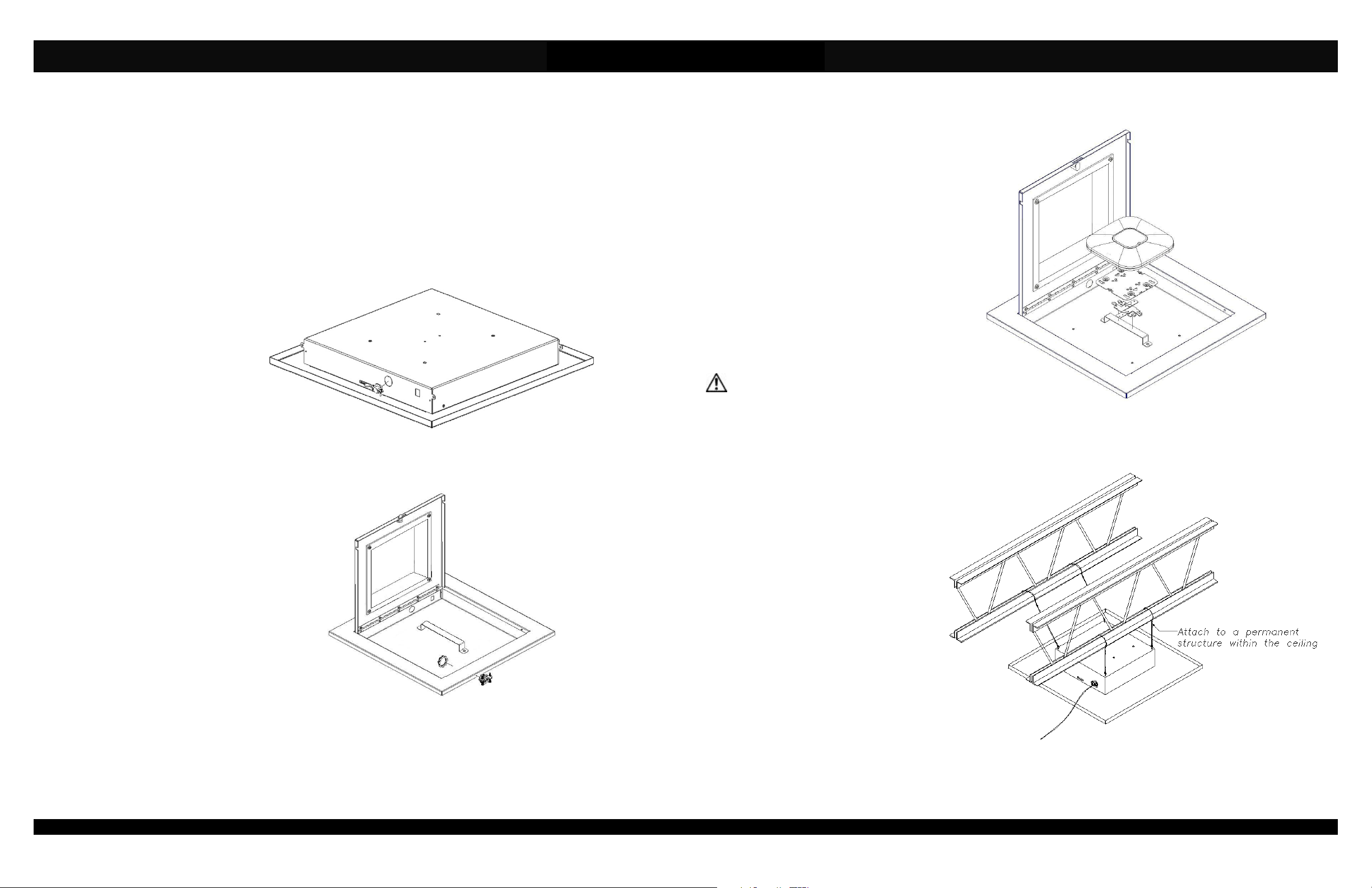
Step 1 – Place the ceiling
enclosure assembly on the work
surface with the keyed doorway
unlocked. The eyebolts will be
used to secure the enclosure with
grid wires (Ref. Figure 1).
Step 2 – Install the cable clamps.
Remove the hole cover(s) from
the inside of the enclosure. Insert
the cable clamp through the hole
with the nut installed from the
inside of the enclosure. If using
Power Over Ethernet (P.O.E.) use
1 cable clamp. If P.O.E. is not
being used, install both cable
clamps and bring power and
Ethernet into the enclosure
through separate clamps (Ref.
Figure 2).
Figure 2 – Installation of cable clamp(s)
Page 2
Figure 1.
Installation Instructions
Model Number 1059-00
Step 3 – (Any manufacturer’s access
points) Install the access point’s mounting
plate to the enclosure’s “T-Bar” bracket
using the manufacturer’s instructions for
attaching the mounting bracket to a ceiling
tile grid (T-Bar). Attach the Access Point to
the mounting plate. (Ref. Figure 3).
Step 4 – Remove the ceiling tile and replace
it with the completed access point enclosure
assembly.
Step 5 – Use minimum 12-gauge grid wire to
secure the access point enclosure in the
ceiling grid. Attach one end of the wire to the
eyebolts and the other end to a permanent
structure within the ceiling such as a ceiling
joist (Ref. Figure 4).
**IMPORTANT** - This is an important
safety feature that could prevent human
injury or damage to the access point,
should the unit become dislodged from
the ceiling grid.
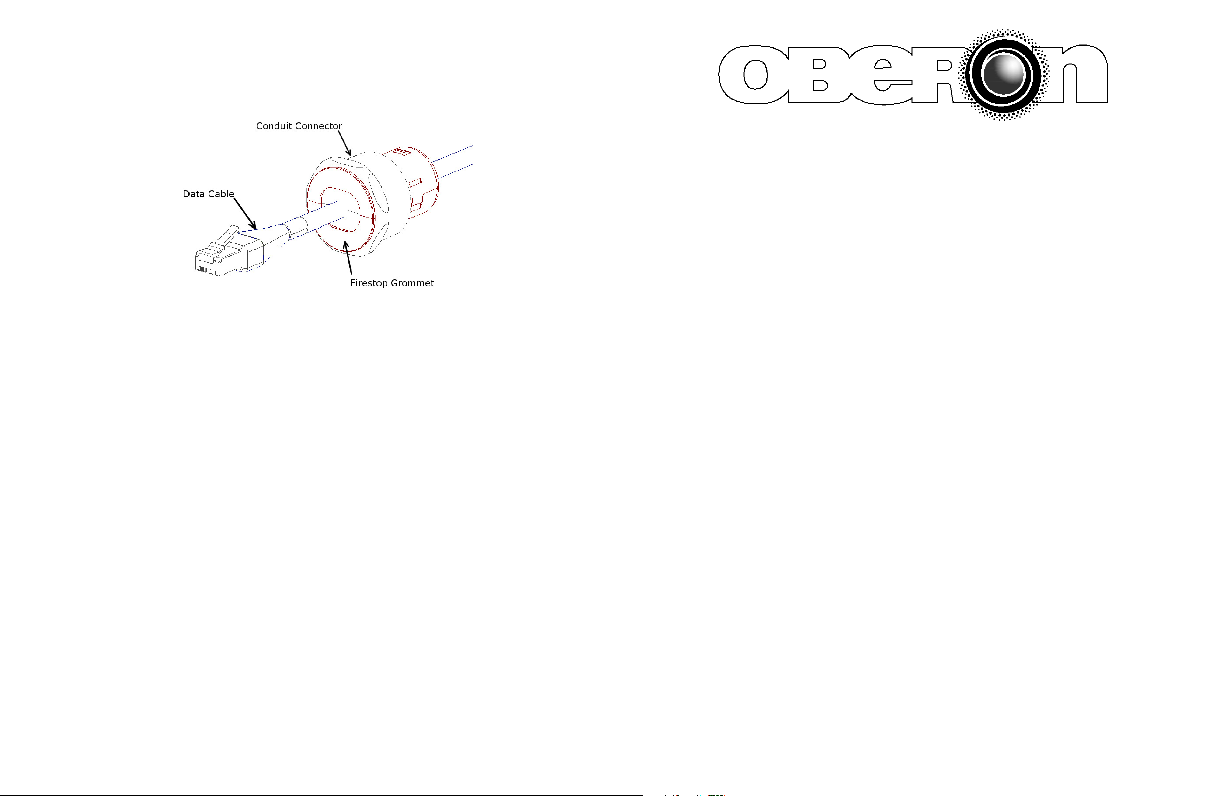
Step 6 –
required) through the conduit connectors
located on sides of the access point
enclosure. In order to maintain a separation
of signal and power, install the data and
power cables through opposite sides of the
enclosure utilizing the two knock-outs
provided. Pull the data cable through the
conduit connector far enough to allow
attachment to the access point (8" - 10").
Snap the grommet on to the cable and slide
it inside the conduit connector.
Run the data and power cable (if
Step 7 – Attach data and power cables to
the access point through the access door
then tighten the screws on the cable clamp.
Step 8 – Close and lock the access door.
The installation is now completed.
Page 3
Figure 3 – Install Access Point in enclosure.
Figure 4 - View showing enclosure installed in ceiling grid.
(877) 867-2312 • www.oberonwireless.com
Rev. 7A - 06/05/14 Oberon, Inc. •••• 1315 South Allen Street •••• State College, PA 16801 Copyright 2013
MODEL 1059-00
Installation Instructions
**** WARNING ****
Please thoroughly read the product warning below
Figure 5 – Pull the data cable through the conduit connector far enough to allow attachment to the access point (8" - 10").
Snap the firestop grommet around the data cable so that there are no air gaps.
Page 4
before installation to provide for a safe work
environment.
1. Ceiling mounted products should be installed in accordance with National Electric Code paragraphs 300.10 (Electrical
Continuity of Metal Raceways and Enclosures) and 300.11 (Securing and Supporting). Independent support wires or
other means must be used for the installation of this product in the ceiling. Acoustical, suspended, false, drop and
concealed spline ceiling grid work is not designed to support the weight of this product. Oberon’s ceiling mounted
products have four support wire tabs on the back box. These tabs shall be used for supporting the product with
independent support wires, wire rope, threaded rod, or other secure support means of adequate gauge and fire
resistance.
2. When closing the enclosure access door, be sure that the cam lock is completely engaged to prevent the access door
from accidentally swinging open.
3. When opening the enclosure door, be sure to support the door to prevent the door from accidentally falling open.
4. This enclosure has a maximum operating ambient of 55º C (131º F), the temperature within the enclosure may not
exceed this temperature, depending on power dissipation within enclosure.
5. A minimum air clearance of 1“ between the housing of the access point and the enclosure side walls must be
maintained for the safe operation of the equipment.
6. This product is intended to be installed by trained personnel.
7. Only Listed ITE and Listed AC Receptacles shall be installed within the enclosure.
8. This product is to be repaired by personnel trained by the manufacturer or returned to the manufacturer for repair or
replacement.
9. Maximum weight to be installed in the unit is 25 lbs.
10. All knockouts, openings, and holes shall be sealed with a plug constructed of metal, or a non-metal material that
complies with UL 2043 or UL 1479.
11. All unused mounting holes should be sealed with tape or other material that complies with UL 1479.
12. If AC power is used inside the enclosure, connect the ground wire to the green ground screw located near the
knockout in the backbox.
Page 1
 Loading...