

Installation Instructions
Model Number 1058-08-ANT5-F
Assembly Components:
- Enclosure Model 1058-08-ANT5-F assembly – 1 each
- 3/4” Trade size cable clamps – 1 each
- Fire Block Foam – 1 each
- hanger wire – 8 each
- Keys for access door lock – 1 each
- Installation Instructions – 1 each
- Stainless Steel Mounting Brackets and Hardware Kit – 4 each
- Internal universal equipment mounting plate – 1 each
If any of these items are missing, contact your Oberon representative.
Find a flat work surface to assemble the enclosure and any other network/cellular components prior to mounting in ceiling.
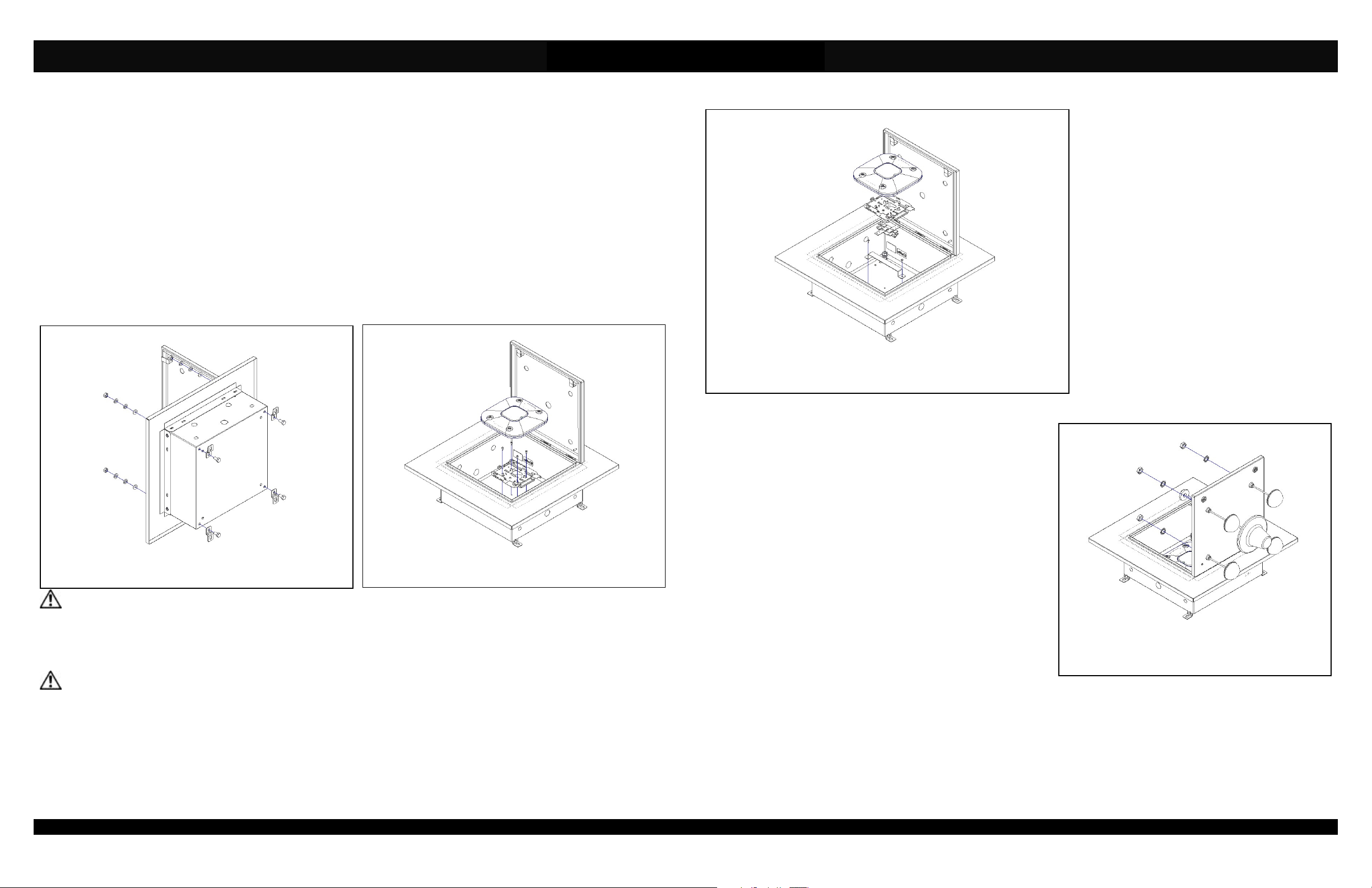
Step 1 – Place the enclosure assembly back side down on the work surface and keyed doorway unlocked. Remove the internal mounting
plate if needed and the desired number of knockouts on the sides and door of the enclosure.
Figure 1
Figure 2
**IMPORTANT** - The brackets must be assembled in the order shown to maintain a watertight seal.
Step 2 – Flip the enclosure to one of its sides. Remove the rubber hole plugs located on the under side of the enclosure. Attach the
mounting brackets (Figure 1) per the provided Assembly Instructions. Place the back side of the enclosure down on the work surface. If
previously removed, install the mounting plate again with its respective hardware.
**IMPORTANT** - Determine the correct access point installation method based on the manufacturer.
Step 3a – (For Cisco AP’s Only) The mounting holes for Cisco AP’s are located in the mounting plate. Standard Cisco mounting brackets
as well as “Bracket 2” can be attached so the “Cisco” logo of the AP is parallel to the hinge. For “Bracket 1” the logo of the AP will be
mounted perpendicular to the hinge. Securely fasten the access point’s mounting plate to the mounting holes on the mounting plate of the
enclosure using four (4) # 8-32 self tapping screws. Attach the Access Point to the mounting plate (Figure 2).
Page 2
(877) 867-2312 • www.oberonwireless.com
Rev. A1 05/23/13 Oberon, Inc. •••• 1315 South Allen Street •••• State College, PA 16801 Copyright 2013
Figure 3
Step 4 – (Optional) With the desired number of knockouts opened, attach
antennas (such as Oberon’s BMANT or DMDUAL) and DAS antennas by
inserting the cables through the door knockouts. Fasten the antennas to the
door per the antenna manufacturer’s instructions. To retain the water and
dust resistance of the enclosure, antennas should have a gasket to fill the
opening. After installation, connect the RF coax cable from the antenna to
the access point (Figure 4). If using Bulkhead connectors, use Oberon
Bulkhead connectors with provided o-ring (P/N 35-NFBLKHD) to maintain
water tightness.
The assembled unit is now ready for ceiling or wall installation.
Page 3
Step 3b – (Any manufacturer’s access points) Install
the provided “T-Bar” bracket by fastening two (2) #8-32
self tapping screws into the enclosure mounting plate.
Attach the access point to the T-Bar bracket using the
manufacturer’s instructions for attaching the access
point to a ceiling tile grid (T-Bar). (Figure 3).
Figure 4
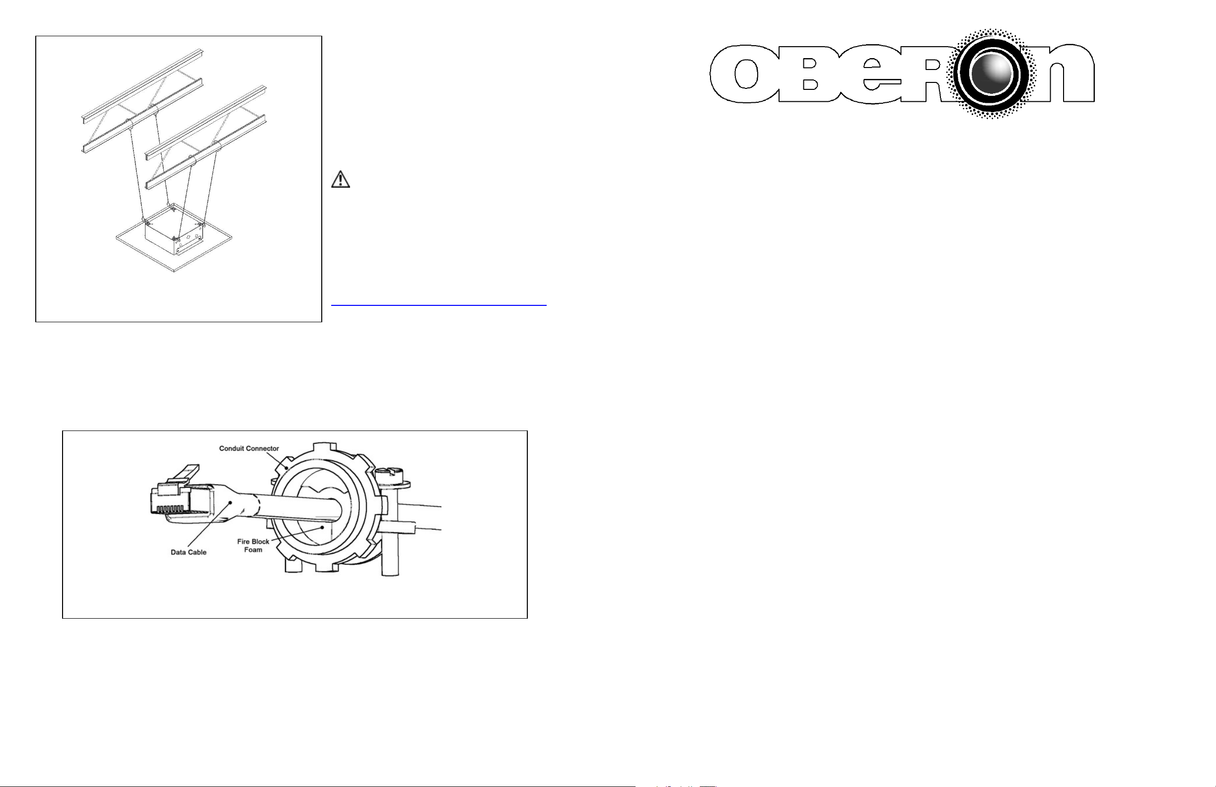
Step 5 – Run the data and power cable (if required) through the
conduit connectors which have been installed in sides of the
access point enclosure. In order to maintain a separation of
signal and power, install the data and power cables through
opposite sides of the enclosure. Wrap the fire stop foam around
the cable and insert foam into the conduit connector and pull the
data cable through far enough to allow attachment to the access
point (8" - 10"). Carefully tighten conduit connector around fire
stop foam just enough to fill in gaps around cable. Be careful not
to over tighten and crush the data cable(s), as this can affect
cable performance. Attach any additional data cables as
necessary and power up the networked devices.
** IMPORTANT** - This is an important safety
feature that could prevent human injury or damage to
the equipment should the unit become dislodged from
the ceiling.
Step 8 – Use hanger wires (included) to support the enclosure.
Attach one end of the wire to the mounting brackets located
along the edge of the back box and the other end to a permanent
structural component of the building such as a joist. Two
Figure 5
Step 9 – Close and lock the access door. Extra force may be necessary to compress the gasket. The installation is now completed.
NOTE: Additional sealing precautions around edges of the enclosure may be necessary.
Figure 8 – Tighten cable clamp around foam fire block so that there are no air gaps. Be careful not to over
tighten and crush the Ethernet cable(s).
supporting grid wires should be attached to each corner.
Reference Oberon’s OPA 1638 drawing (at
http://oberonwireless.com/WebDocs/OPA-1638-10.pdf).
Page 4
MODEL 1058-08-ANT5-F
Installation Instructions
**** WARNING ****
Please thoroughly read the product warning below before
installation to provide for a safe work environment.
1. Ceiling mounted products should be installed in accordance with National Electric Code paragraphs 300.10 (Electrical
Continuity of Metal Raceways and Enclosures) and 300.11 (Securing and Supporting). Independent support wires or
other means must be used for the installation of this product in the ceiling. Acoustical, suspended, false, drop and
concealed spline ceiling grid work is not designed to support the weight of this product. Oberon’s ceiling mounted
products have four support wire tabs on the back box. These tabs shall be used for supporting the product with
independent support wires, wire rope, threaded rod, or other secure support means of adequate gauge and fire
resistance.
2. When closing the enclosure access door, be sure that the cam lock is completely engaged to prevent the access door
from accidentally swinging open.
3. When opening the enclosure door, be sure to support the door to prevent the door from accidentally falling open.
4. This enclosure has a maximum operating ambient of 55º C (131º F), the temperature within the enclosure may not
exceed this temperature, depending on power dissipation within enclosure.
5. A minimum air clearance of 1“ between the housing of the access point and the enclosure side walls must be
maintained for the safe operation of the equipment.
6. This product is intended to be installed by trained personnel.
7. Only Listed ITE products and Listed AC Receptacles shall be installed within the enclosure.
8. This product is to be repaired by personnel trained by the manufacturer or returned to the manufacturer for repair or
replacement.
9. Maximum weight to be installed in the unit is 44 lbs.
10. All knockouts, openings, and holes shall be sealed with a plug constructed of metal, or a non-metal material that
complies with UL 2043 or UL 1479.
11. All unused mounting holes should be sealed with tape or other material that complies with UL 1479.
12. If AC power is used inside the enclosure, connect the ground wire to the green ground screw located near the
knockout in the backbox.
Page 1
 Loading...