

Model 1041-00 Concealed Spline Ceiling Mount Assembly Components:
- 1041-00 Ceiling Mount – 1 each
- #8-32 x 3/8" Screws – 4 each
- Eye Bolts – 2 each
- Cable Clamp - 1 each
- Installation Instructions – 1 each
If any of these items are missing, contact your Oberon representative.
Step 1 – Un-package the 1041-00 unit
and place it on a flat work surface.
Step 2 - Disassemble the unit by
removing the four (4) screws on the
galvanized back panel and placing them
in a location where they will be available
when reassembling the unit.
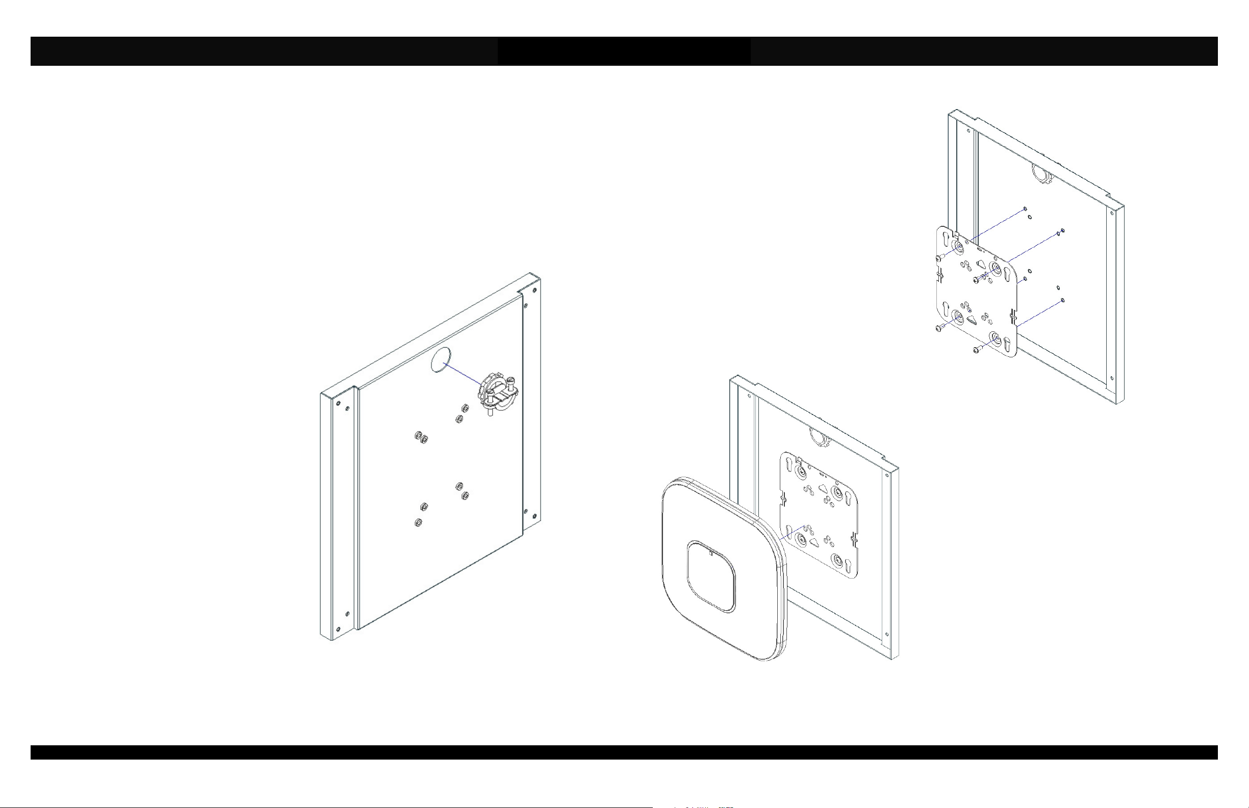
Step 3 - Install the cable clamp through
the 7/8" diameter hole in the galvanized
back panel. Install the cable clamp so that
the two adjustment screws are located on
the outside of the box (ref. Figure 1).
Figure 1: Installation of Cable Clamp
Page 2
Installation Instructions
Model Number 1041-00
Step 4 - Attach the Cisco mounting
plate to the galvanized back panel
using four (4) #8-32 x 3/8" screws.
For Cisco "AIR-BRACKET-1" (shown
in Figure 2)), use the outer hole
pattern, for Cisco "AIR-BRACKET-2",
use the inner hole pattern.
Step 5 - For ease of installation, you
may elect to use a surface mount
receptacle (a.k.a. a "Biscuit" jack) on
the back of the galvanized panel. If
using a surface mount receptacle,
Figure 3: Installation of Cisco Access Point
Page 3
Figure 2: Installation of Cisco Mounting Plate
attach the receptacle to the back side of the
enclosure and run a jumper through the cable
clamp, prior to installing the Cisco AP. If attaching
the Ethernet cable directly, you will need to move to
the location where the enclosure is to be installed
and run the cable from the ceiling through cable jack
before continuing.
Step 6 - Attach the Ethernet cable to the Cisco
access point and mount the access point to the
Cisco mounting plate (ref. Figure 3).
(877) 867-2312 • www.oberonwireless.com
P/N 1751 – Rev. 4 Oberon, Inc. •••• 1315 South Allen Street •••• State College, PA 16801 Copyright 2014
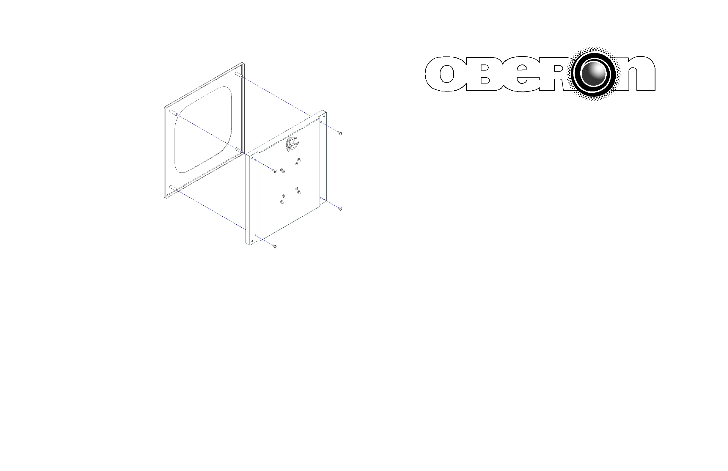
Step 7 – Install the painted front panel
to the assembly by re-installing the
four (4) screws you previously
removed (ref. Figure 4).
Step 8 - Install the 1041-00 enclosure
assembly in the ceiling as you would
install the ceiling tile you removed.
There is a gap between the front and
back panels to accommodate the
concealed spline of the ceiling
assembly.
MODEL 1041-00
Installation Instructions
**** WARNING ****
Please thoroughly read the product warning
below before installation to provide for a safe
work environment.
1. Always consider the hazard to other people:
a. During installation, use warning signs, etc.
b. Don’t work with people directly below the work area as equipment
could fall and cause an injury
2. Be sure to securely fasten the mount to a permanent structure in the
Page 4
ceiling to prevent the mount from becoming dislodged.
Page 1
 Loading...