


MODEL 1030-00
Installation Instructions
**** WARNING ****
Please thoroughly read the product warning below
before installation to provide for a safe work
environment.
1. This enclosure has a maximum operating ambient of 55º C (131º F), the temperature within the enclosure may not
exceed this temperature, depending on power dissipation within enclosure.
2. A minimum air clearance of 1“ between the housing of the access point and the enclosure side walls must be
maintained for the safe operation of the equipment.
3. This product is intended to be installed by trained personnel.
4. This product is to be repaired by personnel trained by the manufacturer or returned to the manufacturer for repair or
replacement.
5. Maximum weight to be installed in the unit is 25 lbs.
6. All knockouts, openings, and holes shall be sealed with a plug constructed of metal, or a non-metal material that
complies with UL 2043 or UL 1479.
7. All unused mounting holes should be sealed with tape or other material that complies with UL 1479.
Installation Instructions
Model Number 1030-00
Assembly Components:
- Wall / Ceiling Enclosure, Model 1030-00 assembly – 1 each
- #6-32 Screws – 4 each
- #8-32 Screws – 4 each
- #10-32 Screws – 4 each
- #6-32 Hex Nuts – 2 each
- ½” Trade Size Cable Clamp
- Keys for access door lock – 2 each
If any of these items are missing, contact your Oberon representative.
Find a flat work surface to assemble the wall/ceiling enclosure and access point prior to mounting.
Step 1 – Step 3 – (Any manufacturer’s access points) Install the access point’s mounting plate to the enclosure’s “T-Bar”
bracket using the manufacturer’s instructions for attaching the mounting bracket to a ceiling tile grid (T-Bar). Attach the
Access Point to the mounting plate. (Ref. Figure 3).
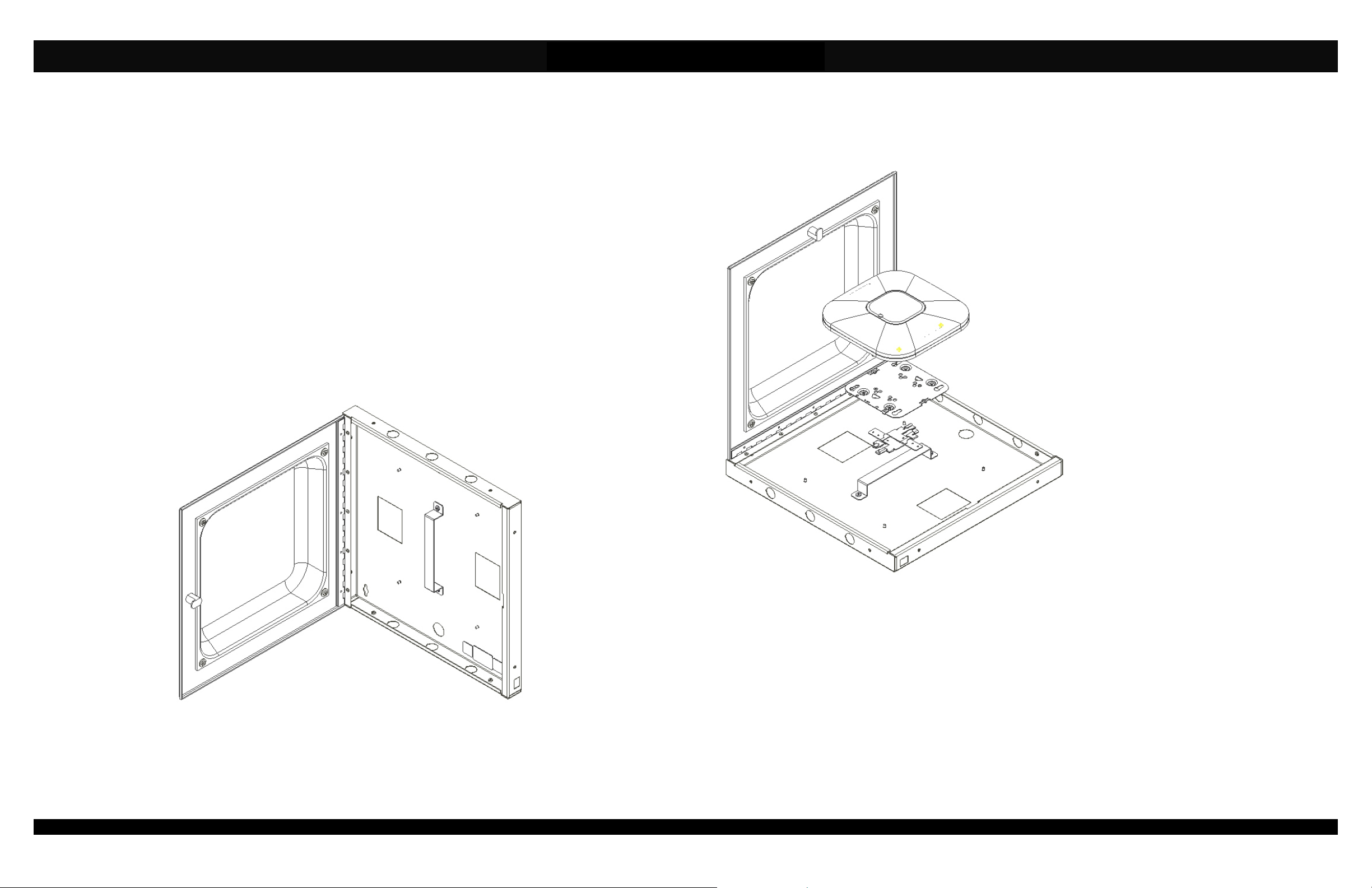
Figure 1 – Model 1030-00 Enclosure Opened .
Step 3 – Decide the best location from which to
bring in the Ethernet cable. There are two (2) ¾”
trade size knockouts located against the back
surface of the enclosure and six (6) ½” trade
size clamps located on the top and bottom
surface of the enclosure. Remove the knockout
that best fits your application. (Note: The
knockouts located on the top and bottom walls
of the enclosure can also be used for external
antennas if required). Install the cable clamp.
Step 4 – Place the enclosure against the surface
to which it will be mounted and mark the hole
locations to drill pilot holes.
NOTE: Openings are provided in the back of
the enclosure so that the unit can be placed
over an outlet. If placing over an outlet,
remove the cover plate of the outlet and
place the enclosure over top. Once the
enclosure has been secured in place, reattach the outlet cover plate inside the
enclosure.
Step 5 – Set the enclosure to the side and drill
holes for wall anchors. Install the wall anchors
and mount the enclosure.
Step 6 – Bring in the Ethernet cable and attach
to the access point.
Figure 2 - Install AP per manufacturer's instruction for T-Bar mounting
Step 8 – Bring in the Ethernet cable and attach to the access point.
Step 9 – Attach the access point to the previously installed access point mounting plate, close and lock the door. Installation is
now complete.
Step 7 – Attach the access point to the
previously installed access point mounting plate,
close and lock the door. Installation is now
complete.
(877) 867-2312 • www.oberonwireless.com
Rev. 7 Oberon, Inc. • 1315 South Allen Street • State College, PA 16801 Copyright 2013
 Loading...