

Oberon 1013-00 User Manual
Installation Instructions
Step 2
Model Number 1013-00
Assembly Components:
- Articulating WAP and Antenna Mount – 1 each
- T-bar bracket – 1 each
- #8 - 32 x 1/4" screw (for attaching access point mounting plate) – 4 each
- #8 - 32 x 7/16 "screw (for attaching antenna) – 4 each
- #6 - 32 x 1/2 "screw (for attaching T-bar) – 4 each
- #6 - 32 x 1/4 "screw (for attaching T-bar) – 2 each
- Wire tie (for cable management) – 2 each
- Installation Instructions – 1 each
If any of these items are missing, contact your Oberon representative.
Find a flat work surface to assemble the mount, access point’s mounting plate, T-bar clip, and antenna(s) prior to mounting
on wall or ceiling.
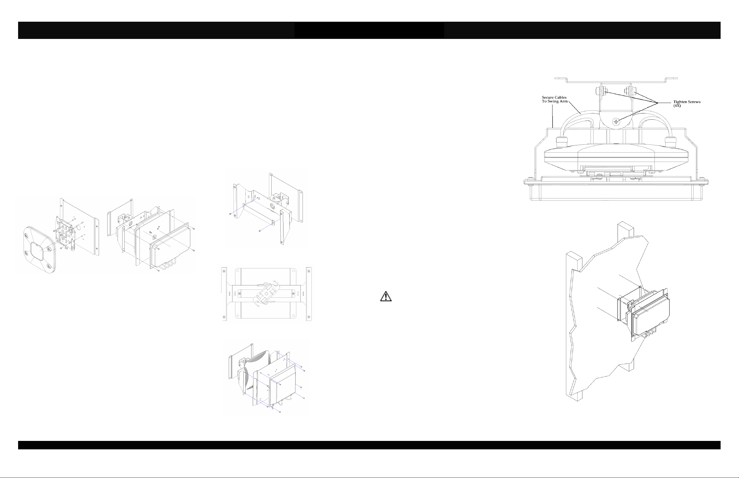
Step 1 – Place the mount assembly on the work surface.
Figure 3
Figure 1 Figure 2
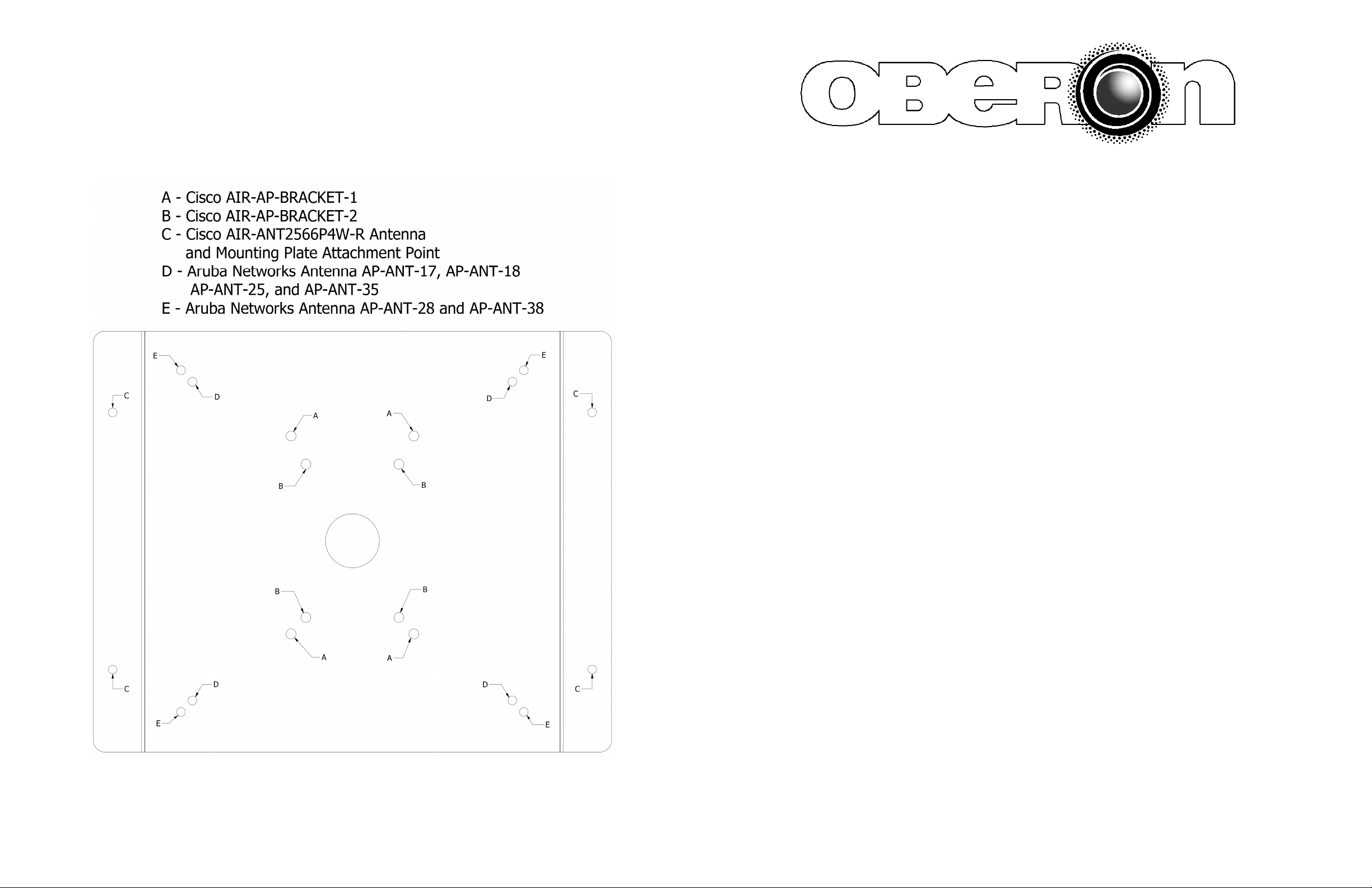
(Cisco Access Points Only) – Use the legend on the back
page to determine which hole pattern to use (Figure 8). Securely
fasten the access point’s mounting bracket to the mounting plate
using the included (4) # 8-32 x 1/4" screws (Figure 1).
Step 3 – Attach the antenna and the mounting plate to the swing arm
of the mount with the (4) included #8-32 x 7/16" screws. (Figure 2).
Step 4 – (Aruba Networks Access Points Only) –Attach the T-bar
bracket to the swing arm (Figure 3) with 2 #6-32 x 14" screw. Then
attach the T-bar clip to the T-bar bracket at a 45º angle and turn
clockwise to attach. Attach the access point the T-bar clip in a similar
fashion.
Step 5 – Attach the mounting plate faced out with the (4) included #832 x 7/16" screws (.Figure 5). Use the legend on the back page to
determine which hole pattern to use (Figure 8) for antenna
attachment. Use #6-32 x 1/2" screws to attach the antenna (Figure 5).
Page 2
Figure 4
Figure 5
Step 6 – Use the provided wire ties to secure
antenna cables to the swing arm. Tighten the
screws snugly in the four locations shown in
Figure 6. This will allow the mount to swivel with
out it freely moving around.
The mount is now ready for wall or ceiling
mounting
Step 7 – If possible, fasten the bracket to
studs/joists using four #10 screws that are at
least 2" long (Figure 7).
Step 8 – Run the data and power cable (if
required) to the access point.
Step 9 – Articulate the antenna mount to the
desired position and securely tighten down the
screws in Figure 6 to keep the mount in the set
position. The mount can be swiveled on two
axes to provide the desired down-tilt and
azimuth coverage of the directive antenna..
Installation is complete.
**IMPORTANT** - It is important that the
mount is securely fastened to the wall or
ceiling to prevent human injury or damage to
the access point.
Page 3
Figure 6
Figure 7
(877) 867-2312 • www.oberonwireless.com
Rev. 08/05/2014 Oberon, Inc. • 1315 South Allen Street • State College, PA 16801 Copyright 2014
MODEL 1013-00
Installation Instructions
**** WARNING ****
Please thoroughly read the product warning
Page 4
Figure 8
below before installation to provide for a safe
work environment.
1. Always consider the hazard to other people:
a. During installation, use warning signs, etc.
b. Don’t work with people directly below the work area as equipment
could fall and cause an injury
2. Be sure to securely fasten the mount to the wall to prevent the mount
from becoming dislodged.
Page 1
 Loading...