

Oberheim GM-400 Operating Manual
VISCOUNT - JOINT VENTURE
Oberheim
GM-400
DIGIT AL SIGNAL PROCESSOR
OPERATING MANUAL
CAUTION
RISK OF ELECTRIC SHOCK
DO NOT OPEN
WARNING! TO REDUCE THE DANGER OF ELECTRIC SHOCK:
DO NOT REMOVE COVER (OR BACK)
DO NOT EXPOSE THIS APPLIANCE TO RAIN OR MOISTURE
NO USER SERVICEABLE PARTS INSIDE
REFER SERVICING TO QUALIFIED SERVICE PERSONNEL
This simbol is intended to
alert the user to the presence
of important operating and
maintenance (servicing)
instructions in the literature
accompanying the appliance.
This simbol is intended to alert
the user to the presence of
uninsulated “dangerous
voltage“ within the product’s
enclouser that may be of
sufficient magnitude to
constitute a risk of electronic
shock to persons.
“INSTRUCTIONS PERTAINING TO A RISK OF FIRE,
ELECTRIC SHOCK, OR INJURY TO PERSONS“
IMPORTANT SAFETY INSTRUCTIONS
“INSTRUCTIONS
PERTAINING TO A RISK OF FIRE,
ELECTRIC
SHOCK, OR INJURY TO PERSONS“
IMPORTANT
SAFETY INSTRUCTIONS
WARNING:
When using electric products, basic precautions should always be
fallowed, including the following:
1) Read all instructions before using the product.
2) To reduce risk of injury, close supervision is necessary when product is used near
children.
3) Do note this product near water – for example, near a batnub, washbowl, kitchen
sink, in a wet basement, or near a swimming pool, or the like.
4) This product, either alone or in combination with an amplifier and headphones or
speakers, may be capable of producing sound levels that could cause permanent
hearing loss. Do not operate for a long period of time in high volume level or at a
level that is unconfortable. If you experience any hearing loss or ringing in the
ears, you should consult an audiologist.
5) This products should be located away from heat sources such as radiators, heat
register, or other products that produce heat.
6) The power supply cord of the instrument should be unplugged from the outlet
when left unused for a long period of time.
7) Care should be taken so that objects do not fall and liquids are not spilled into the
enclosure of the instrument.
8) The products should be serviced by qualified personnel when:
a. The power supply cord or the plug has been demaged; or
b. Objects have fallen, or liquid has been spilled into the product; or
c. The products has been exposed to rain; or
d. The products does not appear to operate normally or exibist a marked
change in performance; or
e. The products has been dropped, or the enclosure demaged.
9) Do not attemp to service the product beyond that described in the usermaintenance instructions. All other servicing should be referred to qualified
personnel.

Oberheim GM 400
Digital Signal P r oc essor
-
69
-
CONTENTS
Contents:
....................................................................................................page 69
1. Introduction:
1.1 Precaution ............................................................................................. page 71
2. Description of controls and connector s:
2.1 Front panel.............................................................................................. page 72
2.2 Rear panel...............................................................................................page 73
3. Installation and instru ctions for use:
3.1 Connection examples.............................................................................. page 74
3.2 Some advice s for cor r e c t u s e o f the GM 4 0 0 ............................................page 75
3.3 Stru c t u r e o f t h e G M 400........................................................................ page 77
4. Play mode:
4.1 Keys and controls.................................................................................... page 78
4.2 Selec t in g a memo r ized patc h ...................................................................page 79
4.3 Programming ..........................................................................................page 80
5. Edit mode:
5.1 Keys and controls.................................................................................... page 81
5.2 Master level ........................................................................................... page 84
5.3 Memorizing a p a t c h ..................................................................................page 84
6. Effects:
....................................................................................................page 86
6.1 Compressor (CMP) ................................................................................ page 87
6.2 Distortion (DST) .....................................................................................page 89
6.3 Equalizer (EQ) .......................................................................................page 91
6.4 Amp simulator (AMP) .............................................................................page 94
6.5 Modulation (MOD) ................................................................................. page 96
6.6 Special effects 1 (SP1) ..........................................................................page 101
6.7 Special effects 2 (SP2) ..........................................................................page 104
6.8 Delay (DLY) ...........................................................................................page 107
6.9 Reverberation (REV) ............................................................................. page 111
6.10 Noise gate (NG) ...................................................................................page 124
6.11 The Midi Foot Controller page................................................................page 124

Oberheim GM 400
Digital Signal P r oc essor
-
70
-
7. Utility Mode:
7.1 Midi ........................................................................................................page 126
7.2 Program Table .......................................................................................page 128
7.3 Dump .....................................................................................................page 129
7.4 Tuner .....................................................................................................page 130
8. Initialization procedur e:
8.1 Factory settings ..................................................................................... page 131
8.2 Dsp self-test ...........................................................................................page 132
9. Annex:
9.1 Types of connectors used........................................................................page 133
9.2 Gloss a r y o f t e r ms use d ............................................................................page 133
10. Technical specifications
........................................................................page 134
Midi Implementation Chart ...........................................................................page 135

Oberheim GM 400
Digital Signal P r oc essor
-
71
-
1. INTRODUCTION
1.1 PRECAUTION
The following is a list of a number of simple precautions to be adopted when using and
maintaining the instrument in order to avoid damage to its mechanical and electronic
structures:
•
To avoid the risk of el ectric shock, never make the connections or use the instrument with
wet hands.
•
Never apply excessive force to the instrument's mechanical parts and keys.
•
Do not stress the instrum ent in transit or during use.
•
Do not place the instrument close to heat sources, in excessively damp or dusty places or
close to strong magnetic fields.
•
When possible, do not place the instrument close to units which generate strong
interference, such as radio and TV sets, monitors, etc.
•
Never insert foreign bodies or liquids of any kind inside the instrument, for any reason.
•
Never use solvents on the instrument's finishes. To clean, use only a soft cloth di pped in
wate r.
•
The inside of the instrument does not contain any parts requiring maintenance by the user.
Never attempt to carry out repairs or modifications to the instrument; always contact
qualified personnel for any repairs.
•
Only connect foot-switches with normally open contact. Prolonged use of unsuitable pedal
units causes serious damage to the instrument's electronic components.
•
Disconnect the power supply lead from the mains socket if the instrument is to be out of use
for long periods.
•
Use only an original power adaptor or one which complies in full with the manufacturer's
specifications. Check that the mains voltage is as indicated on the body of the adaptor.
•
Do not expose the instrument to excessive heat sources, direct sunlight, excessive
vibration or violent knocks.
•
Before moving the instrument, always disconnect all wires.
Oberheim GM 400
Digital Signal P r oc essor
-
72
-
2. DESCRIPTION OF CONTROLS AND CONNECTORS
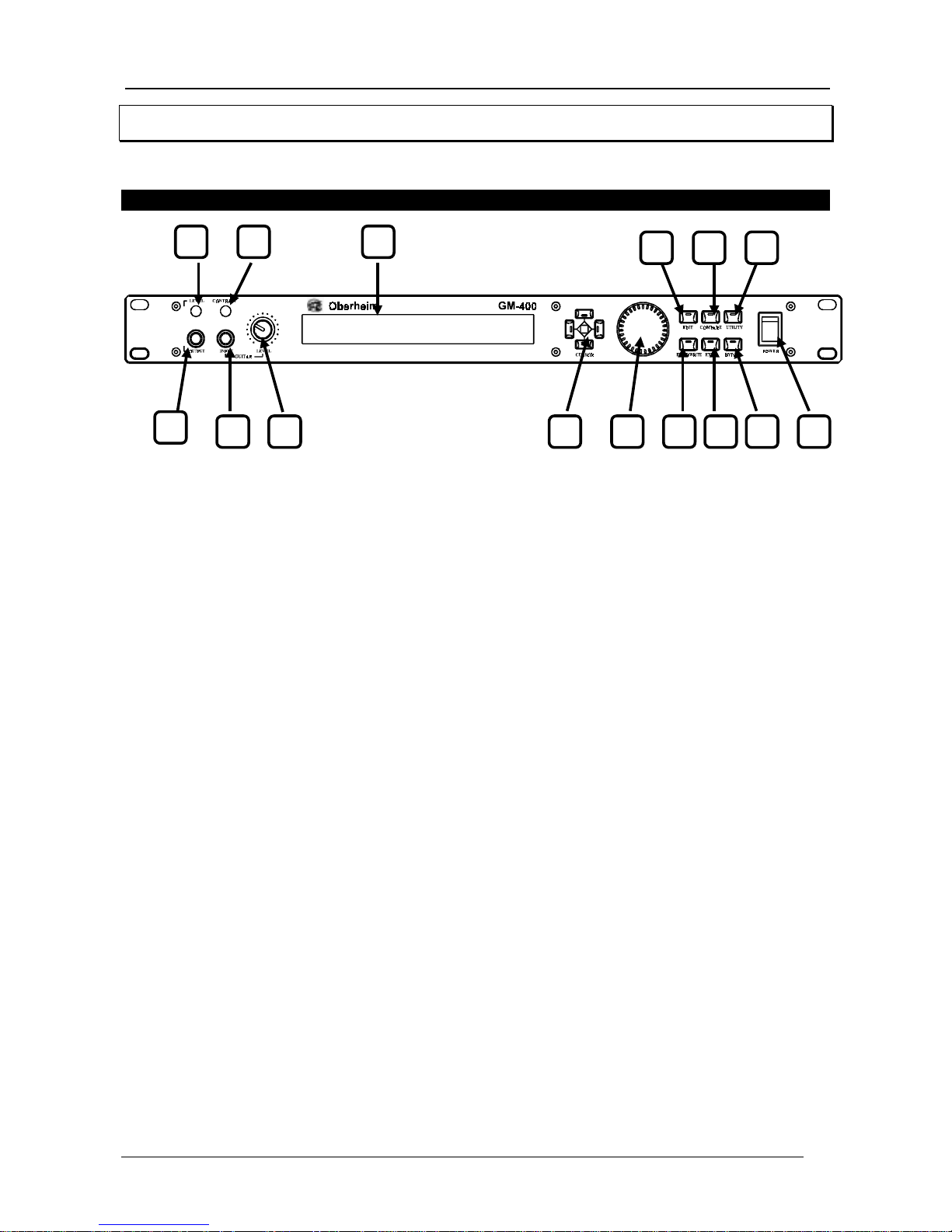
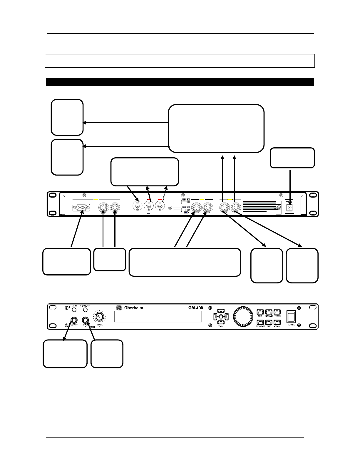
2.1 FRONT PANEL
1. Phones Output
: this socket is a headphones output which allows the GM 400 to be used
even without connection to an amplification system.
2. Phones Lev el
: used to regulate the volume of the signal sent to the PHONES OUTPUT.
3. Guitar In put
: dedicated input socket for connection of a guitar.
4. Input Level
: regulates the quantity of si gnal supplied as i nput to the GM 400. This setting
is active for both the front and the rear connectors.
5. Lcd Contrast
: regulates the contrast of the liquid crystal display (LCD).
6. Display
: backlit display consisti ng of 2 lines of 40 characters each used to di splay various
information, such as the number and name of the memory to be used, the programming
parameters or the input level setting.
7. Cursor
: the four illuminated green keys allow the user to mo ve the flashing cursor around
the display in order to select a parameter for m odification.
8. Encoder
: data input device which can be used to modify the values selected using the
cursor keys. Turn clockwise to increase the selected value, or anti-clockwise to decrease.
9. Edit key, 10. Compare key, 11. Utility key, 12. Enter/Write key, 13. Exit key, 14. Bypass
key
: these keys provide all the main functions needed for using and programming the GM
400.
15. Power key
: key used for switching the instrument on and off.
1
3 4
2 5 6
7 8 12 13 14
9 10 11
15
Oberheim GM 400
Digital Signal P r oc essor
-
73
-
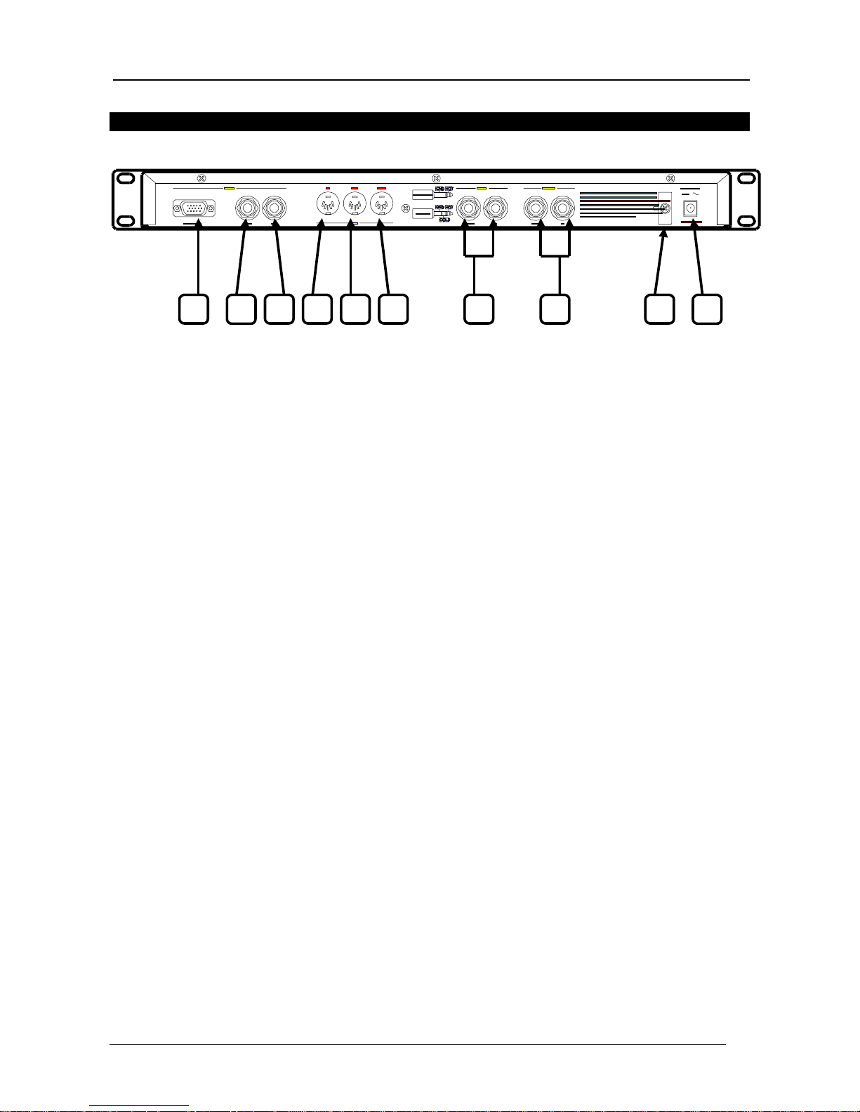
2.2 REAR PANEL
16. Foot Controller
: connector for connection of the Oberheim FC 3000 foot controller
(optional).
17. Hold Switch
: jack for connection of an optional foot-switch which activates the hold delay
function (infinite repetition of a memorized phrase).
18. Tap Switch
: jack for connecti on of an opti onal foot-switch al lowing the tap del ay speed to
be set.
19. Midi In
: five pin DIN connector for reception of Midi messages from a remote M idi source.
20. Midi Out
: five pin DIN connector for transmission of Midi messages generated by the GM
400.
21. Midi Thru
: five pin DIN connector which retransmi ts the MIDI codes as output exactly as
they are received by the Midi In connector. Used to create a chain of Midi devices.
22. L/Mono - R Input
: jack for connection of a remote source to the GM 400. There is a
choice between a stereo connection, usi ng the two inputs simultaneously (the recommended
option) and a mono connection using the L/Mono connector only. The front Guitar Input
connector has precedence over the rear Input connectors. These connectors are of balanced
type.
23. L/Mono - R Output
: the signal processed by the GM 400 leaves the instrument from these
two jacks. There is a choice between a stereo connection, using the two inputs
simultaneously (the recommended option) and a mono connection using the L/Mono
connector only. These connectors are of balanced type.
24. Cable retainer plate
: allows the user to clamp the cable leading from the adaptor securely
in place in order to avoid accidental disconnections.
25. AC adaptor
: connector to take the plug of the adaptor supplied (AC 10.5 V).
16 19 22 23 2517 18 20 21 24
Oberheim GM 400
Digital Signal P r oc essor
-
74
-
3. INSTALLATION A ND INSTRUCTIO NS FOR USE
3.1 INSTALLATION
Audio con n ection s.
•
use only good quality screened cables.
•
m ake the audio connections first and then the mains connection.
Mains conn ection .
•
m ake sure that the mains voltage is as indicated on the instrument.
•
to disconnect the power supply always take hold of the adaptor and do not pull on its lead.
Mixer
Ch. Input
P.A.
System
P.A.
System
Adaptor
10.5 volts
Foot
switches
P.A.
System
or
Ampli
P.A.
System
or
Ampli
Guitar/Bass
Guitar amplifer effects send
Foot controller
Fc 3000
(optional)
Midi unit
Midi controller
Midi Out Midi In
Headphones Guitar
Oberheim GM 400
Digital Signal P r oc essor
-
75
-
•
disconnect the power supply if the instrument is to be out of use for a long period.
3.2 SOME ADVI CE A BOUT CORRECT USE OF THE GM 400
Switch-on.
Before maki ng all the connections make sure that the amplification system volume is turned
down to the minimum setting. Switch on the GM 400 and then adjust the system volume
again. Otherwise, always switch on the GM 400 first and then the amplification system.
Input lev el.
Each instrument has its own output level which may vary depending on circumstances. In
order to obtain the best performance from the GM 400, the input level must be adjusted to suit
the instrument connected. This simple procedure will ensure that the right amount of signal is
sent to the effects processor in order to avoid distortion if the signal i s too strong or hissing i f
the signal is too weak.
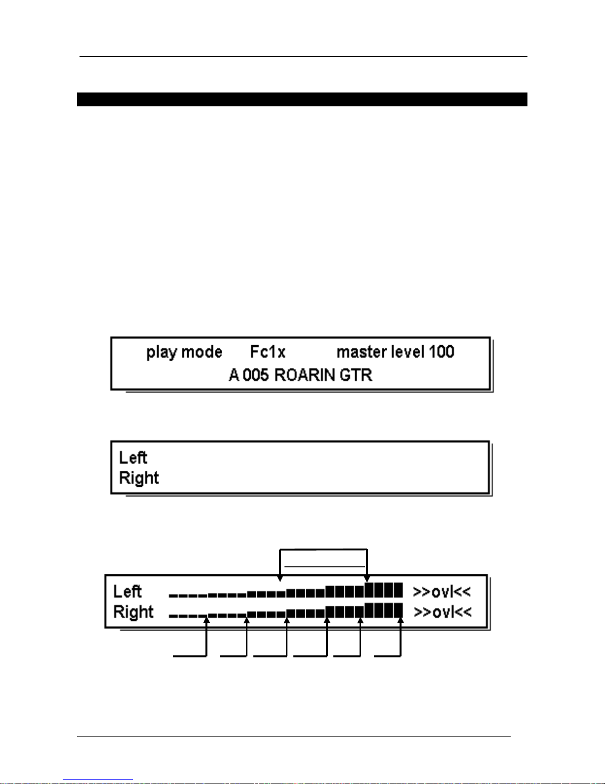
Start the operation by turning the input trimmer to zero and pressing the Exit key whi le the
display is showing the main menu page:
the dis p la y will show:
At thi s point, send the signal to the GM 400 and start to turn the Input trimmer cl ockwise until
the signal brings the following onto the display.
optimum range
-24 dB -18dB -12dB -6 dB -3 dB
0 dB
At this point, reduce the input volume until
>>ovl<<
(the abbreviation of overload, indi cating
an input circuit overload) no longer appears on the display. The illustration shows the

Oberheim GM 400
Digital Signal P r oc essor
-
76
-
optimum operating range, between -12 dB and -3 dB. Press
Exit
to return to the main video
page.
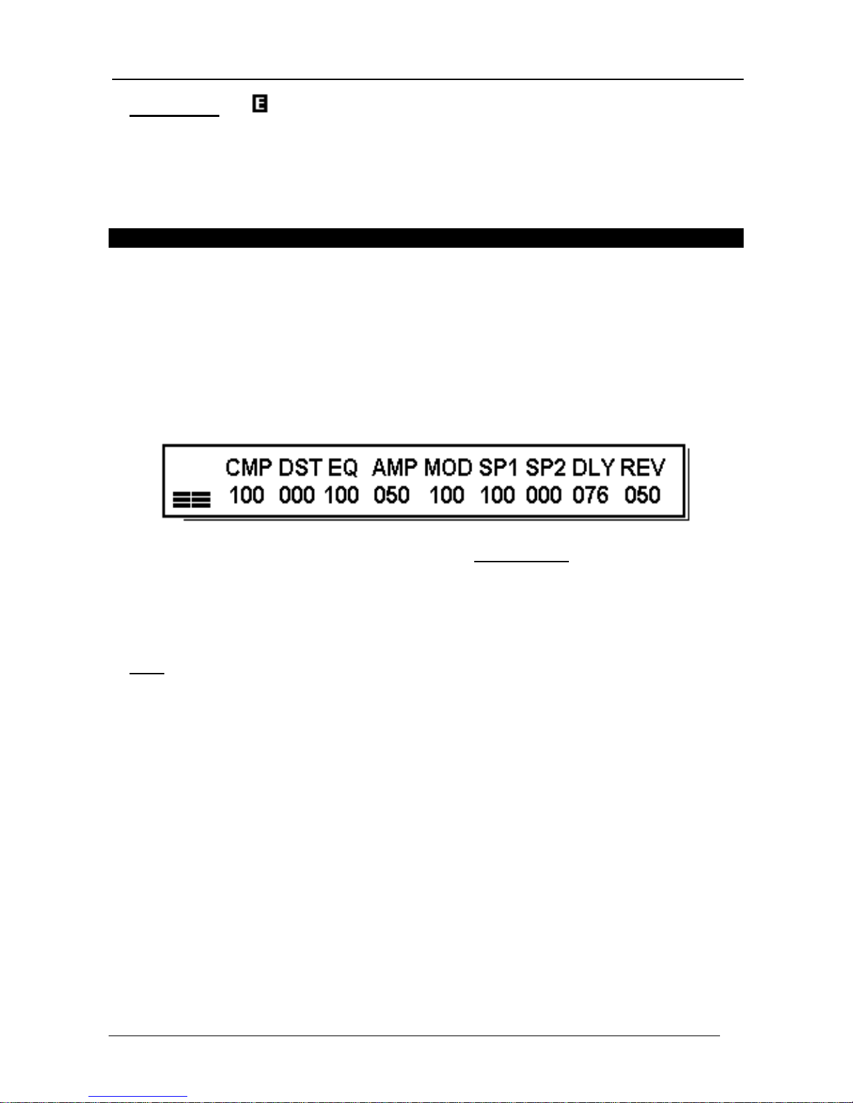
The input signal level can al so be constantly monitored from the mai n video page, using the
bars on the left of the display and illustrated b elo w:
input level
Output level.
The MASTER LEVEL (general output level) shown on the m ain video page:
must be regulated in the same way as the i nput level in order to adapt the output volume to
that of the equipment connected to the OUTPUT(S). Since this parameter can also be
mem orized, m ore details of how it operates will b e d e s c ribed in later sections.
Digital technology and levels.
The GM 400 is an all-digital instrument: this means that som e sim ple rules have to be followed
during programm ing.
In the digital technology, the maximum permitted dynamic threshold is 0 dB; above this level ,
even if it is only reached and exceeded for one moment, so-cal led di gi tal di storti on is created.
Digital distortion has nothing to do with the distortion often required by guitarists, and
generates an extremely unpleasant effect often mi stakenl y thought to be a real malfunction of
the equipment. Since the GM 400 is equipped with filters with an operating range of +/- 14 dB
and it is possible to add together the action of a number of filters operating simultaneously, the
threshold of 0 dB may be exceeded. This must therefore be borne in mind when programming
the GM 400, with frequent checks on the amplification gain introduced by the filters mentioned
above by means of the bypass functions described in the PLAY MODE and EDIT MODE
sections.
Adjusting th e display con tr ast.
The GM 400 is equipped with a large backlit LCD (liquid crystal display). In view of the
characteristics of the LCD system, the contrast has to be adjusted to suit the angle from which
the operator looks at i t. A trimmer marked CONTRAST on the left of the panel is provided for
this purpose.
Oberheim GM 400
Digital Signal P r oc essor
-
77
-
3.3 STRUCTURE OF THE GM 400
Memory configuration.
The mem ory of the GM 400 is divided into three banks: A, B and C.
Each of them contains 128 memory locations (which from now on we will call patches), giving
a total of 384. They are all at the disposal of the user, who can program them as preferred.
The original factory programming settings for the 128 patches in bank A are maintained
permanently in a separate memory and can be recalled at any moment using a special
procedure described in point 8.1 FACTORY SETTINGS.
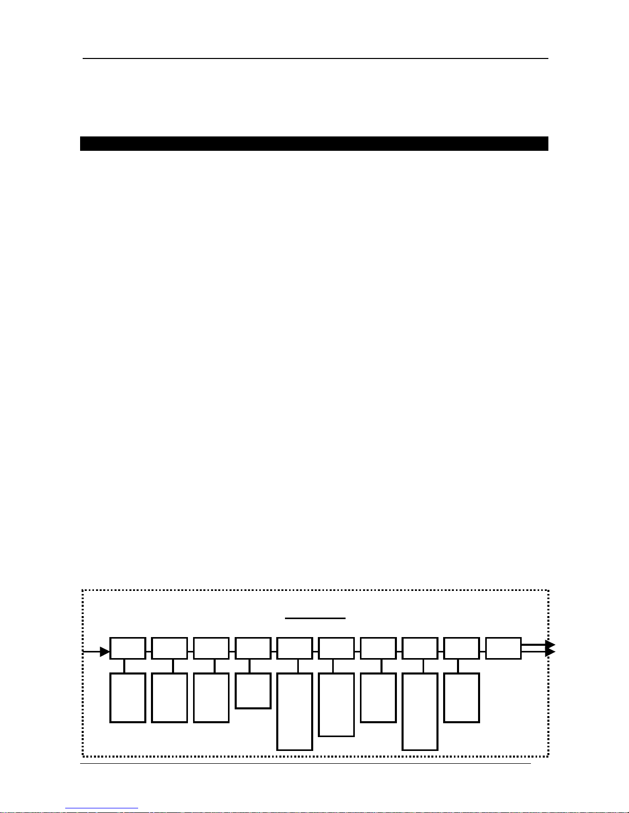
Groups and effects.
The GM 400 is designed to process the signal with up to 9 EFFECTS which can be
programmed at any one ti me. In addition, there i s also a constantly active, programmable
Noise Gate (NG).
The effects are obtained by means of more than thirty algorithms and are arranged into
categories or GROUPS.
Each group is able to contain up to 5 different effects of the user's choice, and only one of
them can be made active. There are 9 groups available, and this gives the maximum number
of effects which can be used simultaneously (plus the noise gate, which is always active):
- COMPRESSOR (CMP): Compressor, Limiter, Dynamic-Processor.
- DISTORTER (DST): Distortion, Overdrive, Crunch.
- EQUALIZER (EQ): Graphic, Guitar, Parametric.
- AMP SIMULATOR (AMP): Guitar, Bass.
- MODULATION (M OD): Chorus, Flanger, Phaser, Tremolo, Vibrato.
- SPECIAL EFFECTS 1 (SP1): Wha-Wha, Double Combination, Double Chorus, Fade-In.
- SPECIAL EFFECTS 2 (SP2): Pitch Shift 1, Pitch Shift 2, 4 Voice Chorus.
- DELAY (DLY): S tandard, Tap, S tereo, M ulti, Metronom e.
- REVERB (REV): Reverb, Gate Reverb, Virtual Chamber.
This can all be summed up by a simple chart:
P A T C H
Input Output
CMP DST EQ AMP M0D SP1 SP2 DLY REV
NG
Comp
Limit
Dyn-p
Dist
Over
Crun
Grap
Guit
Para
Guit
Bass
Chor
Flang
Phas
Trem
Vibr
Wha
Comb
2 Ch.
Fade
Psh1
Psh2
4 Ch.
Stan
Tap
Ster
Multi
Metr
Rev
Gate
Virt
Oberheim GM 400
Digital Signal P r oc essor
-
78
-
4. PLAY MODE
The section which follows will describe the PLAY MODE: we will discuss the way in which the
GM 400 will be used while the patches are being played. The next section, entitled EDIT
MODE, will describe the procedure for programming a patch. This section will refer almost
only to the main video page.
4.1 KEYS AND CONTROLS
Cursor.
Four green illuminated keys to the right of the display and on the left of the Value Encoder are
called CURSOR keys. They allow the user to move the flashing cursor, used to select a
parameter to be m odified, around the display. The top key moves the cursor upwards, the key
on the right moves the cursor to the right, and so on.
Value.
Once the parameter to be modi fied has been selected, the Val ue Encoder al lows the user to
vary its value. Turn the knob clockwise to increase the selected value or anti-clockwise to
decrease. The encoder works dynami cally; in other words, the speed at whi ch it is turned
establishes the speed at which the selected value is varied.
General bypass.
To listen to the signal exactly as it reaches the INPUT socket, the user can completely bypass
the algorithms which process the signal by pressi ng the BYPASS key with the main menu
page on the screen. To confirm this operation, the light in the BYPASS key will begin to flash.
Press the BYPASS key again (the light remains constantly on) to return to the initial
conditions. This type of bypass is referred to as a GENERAL BYPASS to di stinguish i t from
the LOCAL BYPASS to be described in the EDIT MODE section.
Phones ou tpu t.
This socket allows the user to listen to the results of the GM 400 signal processing on
headphones. Once the jack has been connected to the PHONES OUTPUT socket on the left
of the panel, optimize the playback volume as preferred using the PHONES L EVEL trimmer
immediately above the PHONES OUTP UT socket.

Oberheim GM 400
Digital Signal P r oc essor
-
79
-
•
CAUTION !!:
Excessively high playing volumes may seriously damage your hearing: keep
the volume withi n reasonable l i mi ts
.
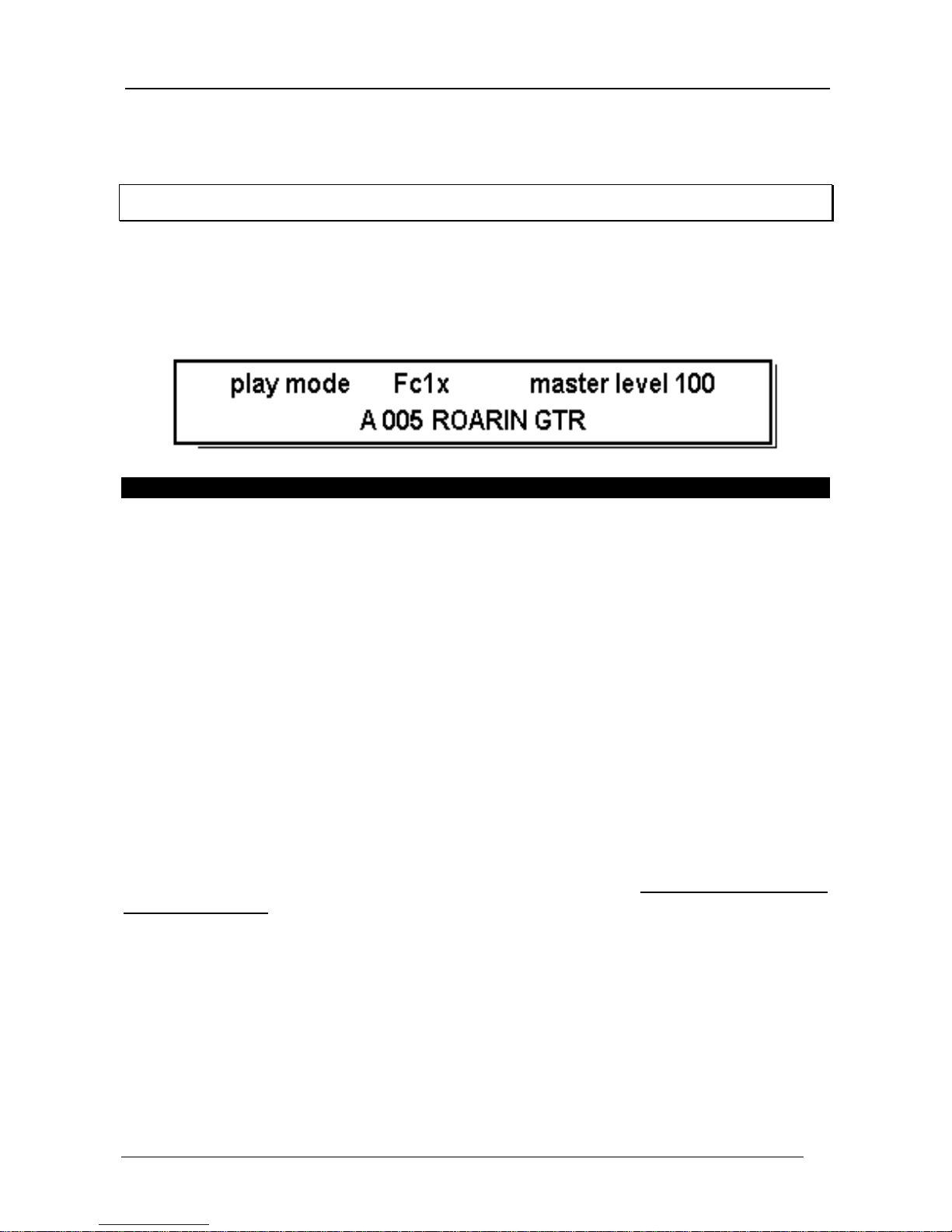
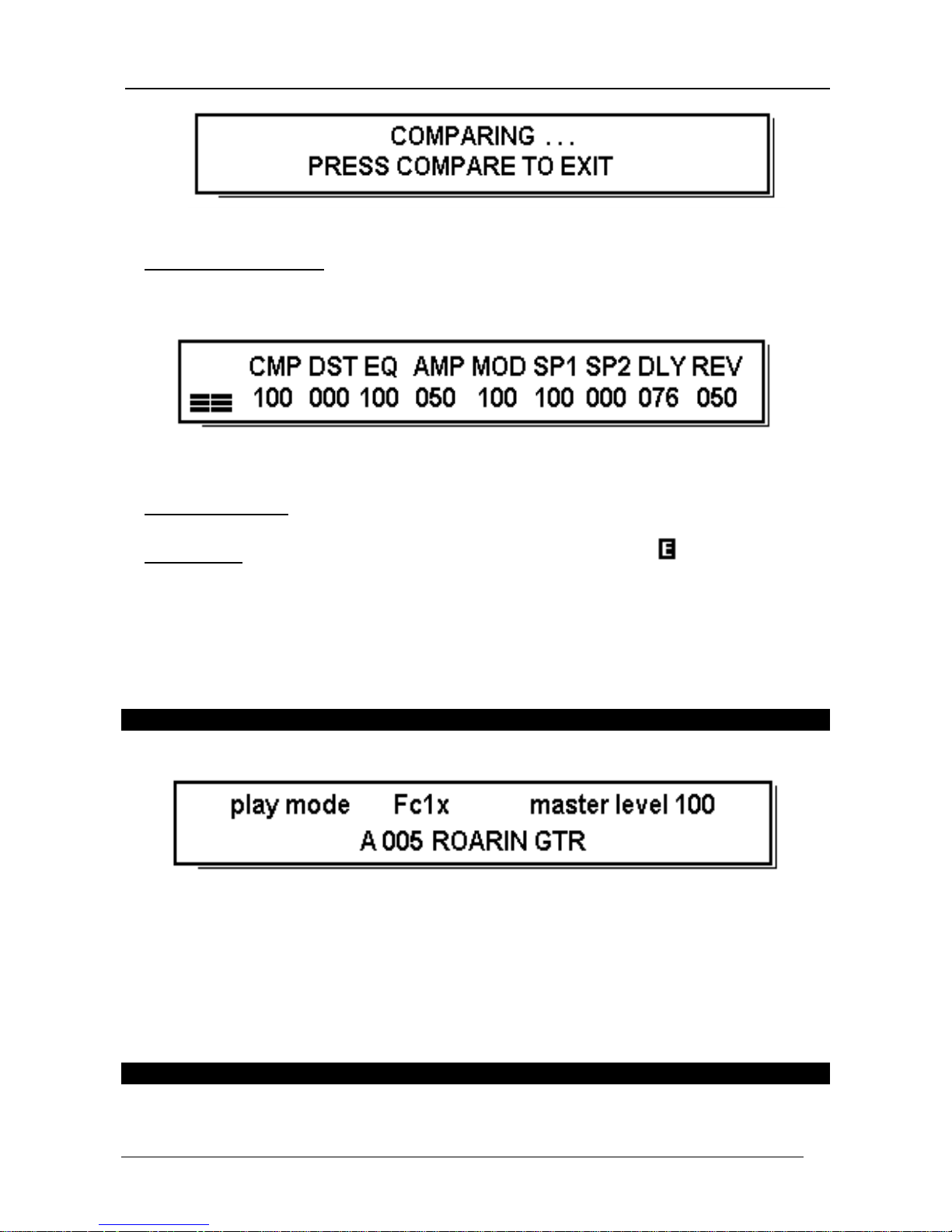
4.2 SELECTING A MEMORIZED PATCH
Play mode indicator Foot controlle r General output volume
Memory bank Memory patch Patch name
Changing the memory bank.
To select a memory bank other than the one which is active:
•
Locate the flashing cursor on the mem ory bank indication using the CURSOR keys.
•
Turn the VA LUE encoder until the required mem ory bank is displayed.
Changing the memory patch.
To select a memory patch other than the one which is active:
•
Locate the flashing cursor on the memory patch indication using the CURSOR keys.
•
Turn the VA LUE encoder until the required mem ory patch is displayed.
Master level.
The MASTER LEVEL parameter controls the general output level of the selected memory
patch: the setting is memorized together with the patch itself. Note that this level is not an
absolute value but depends on the settings made during programming of the individual groups
active.
To modify the MASTER LEVEL value:
•
Use the CURSOR keys to locate the flashing cursor on the MASTER LEVEL parameter.
•
Turn the VA LUE encoder until a playback volume suitable to requirements is obtained.
Oberheim GM 400
Digital Signal P r oc essor
-
80
-
•
CAUTION !!:
an
displayed on the right of the words "play mode"indicates that this
modification has not been memorized in the patch. To make the modification permanent,
refer to point 5.3 MEMORIZING A PA TCH i n the EDIT MODE secti on
.
4.3 PROGRAMMI NG
In PLAY MODE "programming" refers to the operations which can be performed on the
instrument without necessarily having to carry out a complex session with substantial
modification of the processing parameters, for which the EDIT M ODE is required.
The Group levels.
Press the COMPARE key with the main video page on the screen to access the vi deo page
which allows the levels of each individual group to be adjusted.
These parameters regulate the way in which the active groups affect the signal to be
processed. The active groups are those which have been included in the processing chain
during the programming phase and are not in OFF or LOCAL BYPASS status ( the LOCAL
BYPASS status is different from the GENERAL BYPASS already discussed and will be
described in the EDIT MODE section).
•
N.B.:
the level of a group in local bypass or OFF status can be modified, but this will have
no effect on the signal
.
The parameter modified consists of the effect send level (EFFECT LEVEL - see section 6.
EFFECTS for further information) and allows the user to set the influence of the specific group
within the processing chain, wi th values between 0 and 100. The only exception is the DST
group, which does not include parameters for which there is differentiation between the level
of the direct signal and that of the processed signal: in this case, the parameter controlled (the
only one with values between 0 and 64) will be the DRIVE (distortion intensity) value, which is
certainly the most significant parameter in the group concerned.
To modify the operating level of a group:
•
Use the CURSOR keys to locate the flashing cursor on the group level to be modified.
•
Turn the VALUE encoder until an effect suitable to requirements is obtained (it may be
necessary to vary the values of more than one group to obtain the desired results).
Oberheim GM 400
Digital Signal P r oc essor
-
81
-
•
CAUTION !!:
an displayed on the right of the words "play mode" indicates that this
modification has not been memorized in the patch. To make the modification permanent,
refer to WRITE MODE in the EDIT MODE secti on
.
Press the
Exit
key to return to the main menu page.
5. EDIT MODE
The section which follows will describe the EDIT MODE operating method, or in other words
we will discuss the way in which the GM 400 will be used during programming of the patches.
In EDIT MODE, the operator can carry out all the procedures relating to modification of the
parameters connected to the programming of a patch. The procedure for saving a new or
modified patch in one of the 384 locations available will also be e xplained.
5.1 KEYS AND CONTROLS
For use of the CURSOR keys and the VALUE encoder, see PLAY MODE section.
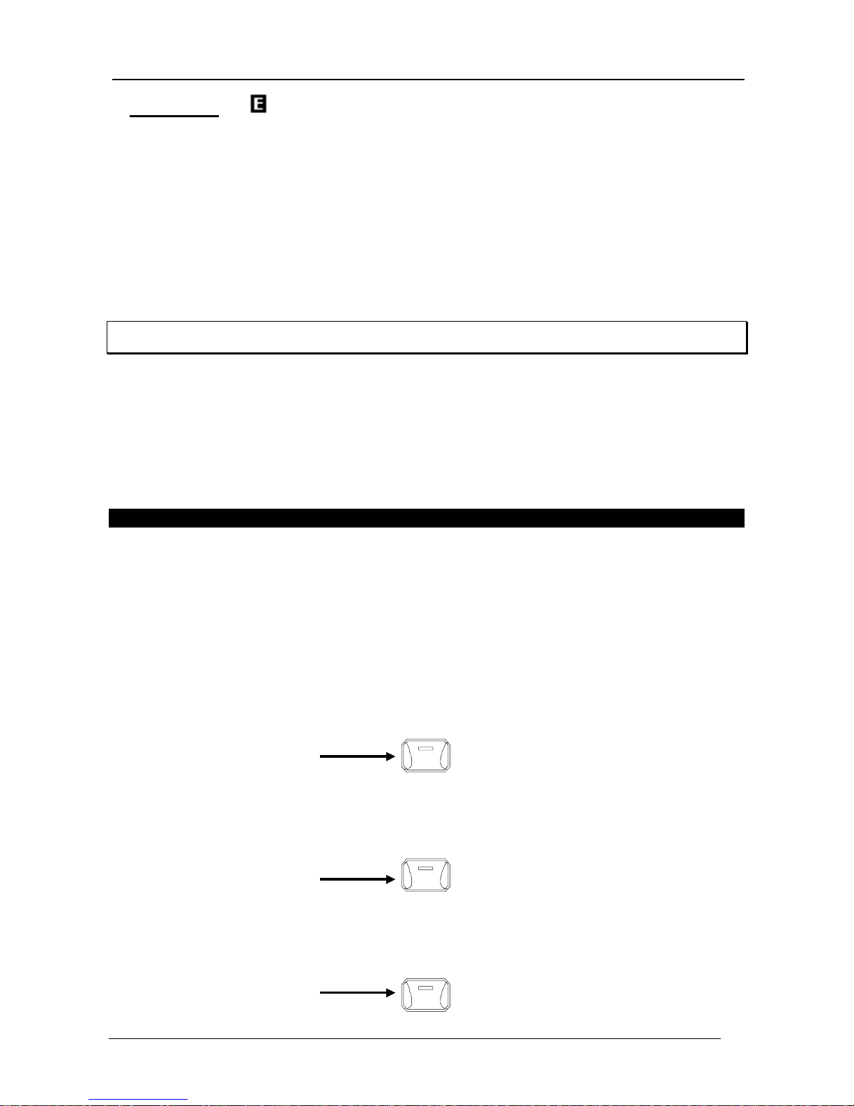
Edit and Exit keys.
The EDIT key gi ves access to the EDIT pages. Once the EDIT function has been accessed,
this key allows the user to display pages after those shown on the display, i n accordance with
the instrument's structural hierarchy. The following is a simple example:
MAIN MENU PAGE
EDIT
MAIN EDIT PAGE
EDIT
GROUP EDIT PAGE
Oberheim GM 400
Digital Signal P r oc essor
-
82
-
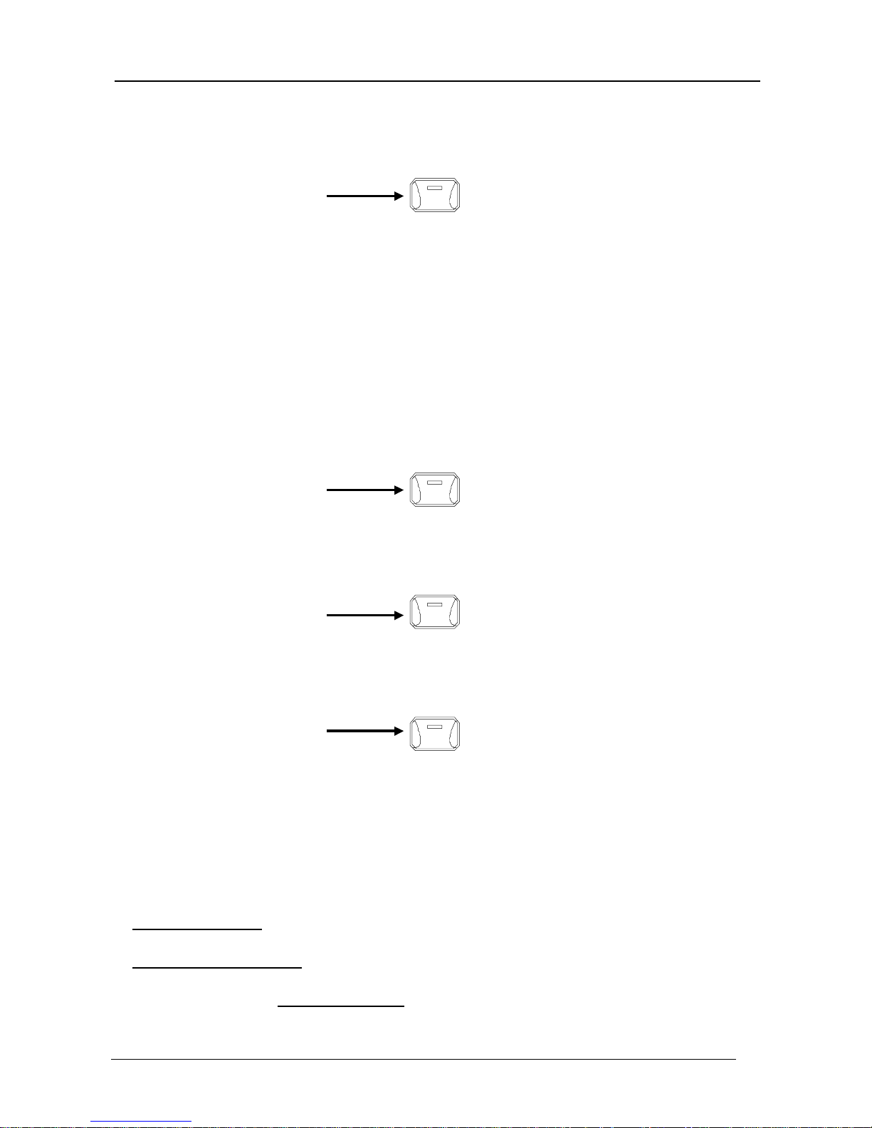
EDIT
1st EFFECT EDIT PAGE
EDIT
2ND EFFECT EDIT PAGE (IF PRESENT) ....
The red light in the EDIT key will remain on as long as the edit page shown on the display is
not the last in the sequence.
The EXIT key works in exactly the opposite way to the EDIT key: it all ows the user to move
one page back from the one shown on the displ ay, passi ng through the hi erarchi cal structure
in the opposite direction to that explained for the EDIT key:
EFFECT EDIT PAGE
EXIT
GROUP EDIT PAGE
EXIT
MAIN EDIT PAGE
EXIT
MAIN M E NU PA GE
Enter/Wr ite key .
This key has two functions:
•
when its light is on: the patch writing function (W RITE MODE) described later in point 5.3
MEMORIZING A PATCH below is active.
•
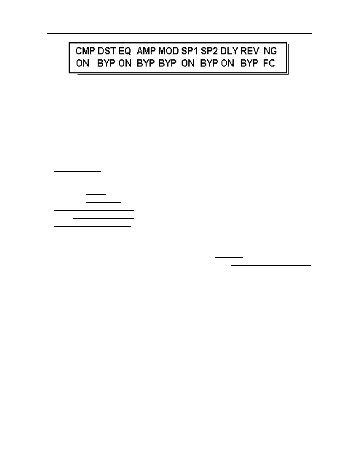
when its light i s flashing: it allows the user to choose between OFF and BYPASS (BYP)
status for a group selected in the main edit video page. Press the EDIT key from the mai n
menu page to obtain the m ain edit page:
Oberheim GM 400
Digital Signal P r oc essor
-
83
-
To set a group in OFF or BYPASS status:
- Select the group using the CURSOR keys or the VALUE encoder.
- Pre s s t h e ENTER/WRITE key (the d is pla y will show O F F/ BYP in alternation).
- Press the EXIT key to return to the m ain m enu page.
•
w hen the light is off: no function available.
Bypass key.
The BYPASS key also provides two functions, but in this case the procedure obtained
depends on the video page on the screen:
•
m ain video page: as we already know , this key provides a GENERAL BYPASS of the entire
chain of effects, or in other words allows the user to listen to the input signal unchanged.
Pressing the key provides two conditions:
- light on: the processing chain is active.
- light flashing: multieffect system in GENERAL BYPASS status.
•
i n the main edit video page: allows the user to choose between BYPASS (BYP) and ON
status for the selected group.
•
in subsequent edit pages: provides a LOCAL BYPASS, meaning that it switches the
selected group only (e.g. DST or CMP) into BYPASS status.
We will try to give a rapid explanati on of the difference between these types of BYPASS and
the types already seen, in order to prevent misunderstandings and allow operators to use the
GM 400 correctly. The LOCAL BYPASS function cuts o ut one group (e.g DISTORTION, EQ
or MODULATION), while the GENERAL BYPASS disables the entire chain of effects
simultaneously. It must be underlined that the two types of BYPASS referred to here are
temporary, unlike the BYPASS ac tivated in the main edit vi deo page, which will be memorized
together with all the patch parameters. It should also be remembered that the OFF and
BYPASS statuse s in th e main edi t vi deo page have the same result in terms of sound. The
difference between these two values in practical terms becomes obvious when the optional
Oberheim FC 3000 foot controller is used, since the foot switches it provides allow the user to
switch any one of the groups set in BYPASS status to ON. On the other hand, the foot
cont ro lle r will have no e ff e c t o n th e g roups in OFF status, w hich will b e c o mpletely o ut o f u s e .
Compare.
This key has two functions:
•
when its light is on: it activates the sound compare function. In other words, it all ows the
user to make a comparison by al ternating the sound modified in an EDIT session (current
situation) with the sound memorized in a patch taken as the starting point for the
modification process. It i s used to check the worth of the new setti ngs before saving them
and replacing the original patch with the modified one. While the comparing procedure is in
progr e s s , t h e d is pla y will show:
Oberheim GM 400
Digital Signal P r oc essor
-
84
-
Press COMPARE again to exit from the function.
•
when its light is flashing: this occurs when the display is showing the main menu page. In
this case, pressing the COMPARE key activates the EDIT page for group l evels already
described in the PLAY MODE chapter.
Press EXIT to return to the m ain m enu page
•
w hen the light is off: no function available.
•
CAUTION !!:
When modifications are made to an existing patch an to the right of "play
mode" on the main menu page indicates that the GM 400 is in EDIT MODE. The
modifications made become operational immediately but will not become permanent until a
memorization procedure (described in point 5.3 MEMORIZING A PATCH of this same
section) has been carried out. Otherwise they will be lost when a different memory location
is selected.
5.2 MASTER LEVEL
When programming is complete, users are advised to adjust the MASTER LEVEL (general
volume) parameter as appropriate to the output volume obtained from the sum of the
processes carried out by the individual groups. The parameter is located in the main menu
page, to allow rapid adjustments even during live performances while the mu lti effect devi ce is
in PLAY MODE, and the setting is memorized in the patch together with all the other
parameters.
5.3 MEMORI ZING A PATCH
Oberheim GM 400
Digital Signal P r oc essor
-
85
-
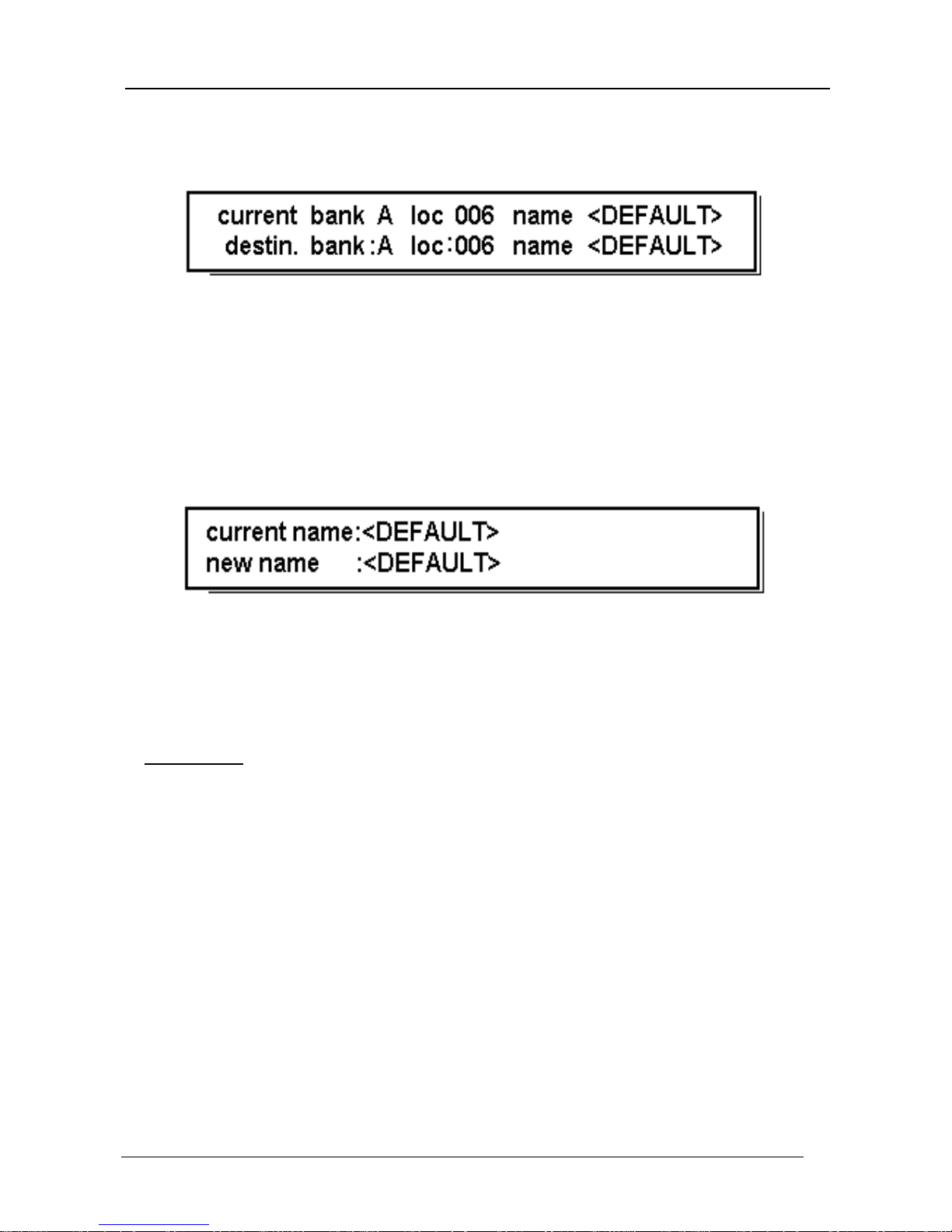
Press the ENTER/WRITE key with the light constantly on to access the patch memorization
func t ion . Th e d is p lay will show t he r ela t iv e page:
which shows:
•
the current memory location (CURRENT BANK);
•
the destinati on memory location (DESTIN. BANK). The GM 400 automatically offers the
current location, as shown in the above example.
To modify the BANK and location (LOC), use the CURSOR keys and the VALUE encoder. To
change the NAME, press the flashing UTILITY key to display:
then select the character to be modified using the CURSOR keys and change it using the
VALUE encoder. At this point (whether you are in the location or name modifi cation page)
press the ENTER/WRITE key again to memorization the patch in the destination memory
location. A short message will c on f ir m that th e operation has been completed.
•
CAUTION !!:
a modification to a patch can be memorized quickly by simply pressing the
ENTER/WRITE key twice in successi on
.
Oberheim GM 400
Digital Signal P r oc essor
-
86
-
6. EFFECTS
The chapter which follows describes all the effects in each group. In addition to a brief
description of the characteristics of the effect itself, all the parameters relating to its
programming will be discussed. All the procedures described start from the main edit video
page.
To access the various programming pages, use the EDIT key, while the CURSOR keys and
the VALUE encoder will a lways be us e d t o modify pa ra meters.
•
USEFUL HINT
:
When programming, always take care to make proper use of the BYPASS
and COMPARE keys previ ously described in the EDIT MODE section
.
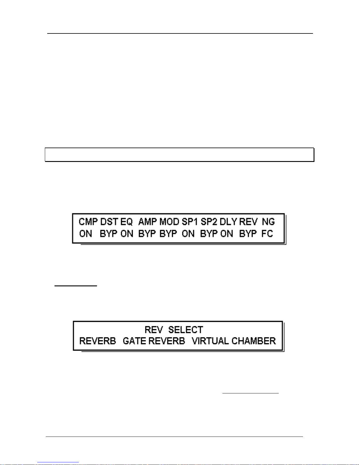
The following is an example of a group edit page:
As stated in the introductory notes, only one effect can be selected from each group. The
effect selected from the group can always be identified because it is the only one which
flashes in the group edit page. To change the sele cted effect, l ocate the cursor on the name
of the effect you require using the CURSOR keys and then press the EDIT key. W e have
emphasized this procedure because the fact that another effect is flashi ng might mislead you
unless this operation is confi rmed by pressing the EDIT key which will bring you to the effect
edit page:
Oberheim GM 400
Digital Signal P r oc essor
-
87
-
which also confirms that the desired effect has been selected.
But now let's move on to ex amine the effects the GM 400 is able to provide.
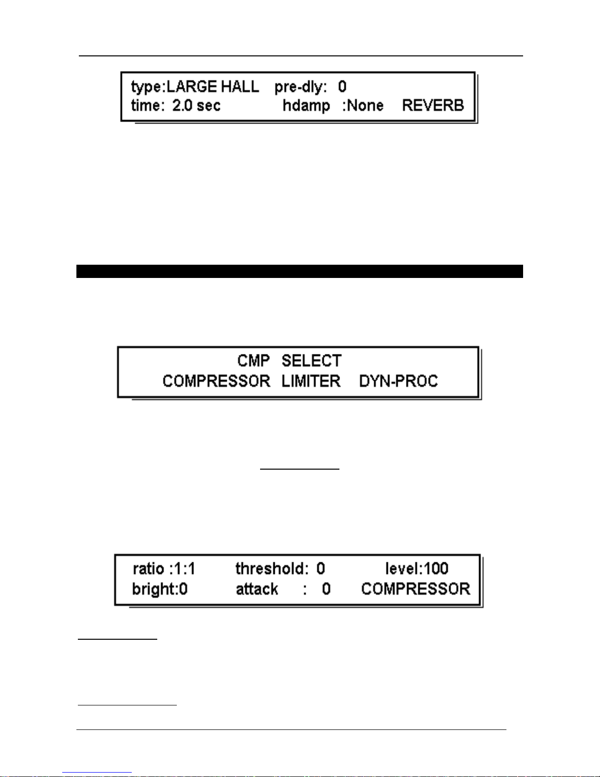
6.1 COMPRESSOR (CMP)
The Compressor page is accessed by selecting CMP in the main edit page and pressing the
EDIT key:
The page shows the 3 effects available in this group:
Compressor, Limiter and Dynamic
Processor.
COMPRESSOR
The Compressor modifies the dynamics of a sound by compressing it. The volume of the
quieter passages is increased while that of the louder passages is reduced. The sound
becomes softer and rounder, w hile at high levels the sustain effect will be prolonged.
Press the EDIT key to access the relative edit page:
Ratio parameter. Range: 1:1, 1.2:1, 1.5:1, 2:1, 3:1, 5:1, 10:1, 20:1, ∞:1
This sets the compression ratio. The 1:1 level will provide a slight compression, while level
∞
:1 w ill g iv e t he maximum co mpressio n.
Threshold parameter. Range: 0 - 45

Oberheim GM 400
Digital Signal P r oc essor
-
88
-
Sets the level of the input signal below which the compression effect will operate. The
operating range runs from -6 dB (Threshold=0) to about -40 dB (Threshold=45).
Bright parameter. Range: 0 - 5
A filter which enhances the high frequencies.
Attack Time param eter. Range: 0 - 100
Regulates the compressor i ntervention ti me. The range varies between 2 milliseconds (value
= 0) and 50 millis econds (value = 100)
Level parameter. Range: 0 - 100
Regulates the level of the output signal in the context of the effects chain.
LIMIT ER
As its name implies, the limiter limits the dynamics of the signal to a value which can be freely
set by the user.
Threshold parameter. Range: 0 - 45
Sets the value of the level of the i nput signal above which the limiter comes into operation.
The range goes from -6 dB (Threshold = 0) to about -40 dB (Threshold = 45).
Release Time parameter. Range: 0 - 10
Sets the time for which the Lim iter effect persists.
Level parameter. Range: 0 - 100
Regulates the level of the output signal in the context of the effects chain.
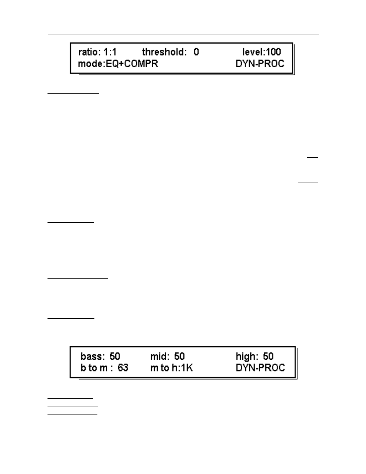
DYNAMIC PROCESSOR
A dynamic spectral processor. This effect features a filter which allows the audio signal and/or
the control signal to be modified in 6 di fferent ways. In this case there are two edi ting pages;
the user switches between them by pressing EDIT.
Oberheim GM 400
Digital Signal P r oc essor
-
89
-
Mode parameter. Range: Dynamic Loudness, Spectral Compressor, Spectral DeEsser,
Spectral Exp/Gate, Eq + Compressor, Eq + Expander
Controls the mode in which the effect works. The functions provided by the modes vary quite
widely.
•
Dynamic Loudness - Enhances the frequencies selected in the crossover (see second
editing page) depending on the total level of the input signal.
•
Spectral compressor - Compresses the frequencies selected in the crossover with
attenuation recovery.
•
Eq + C ompressor - combines the equalizer and the compressor.
•
Spectral DeEsser - Compresses the frequencies selected in the crossover without
attenuation recovery.
•
Spectral Ex p/Gate - E x pands the frequencies selected in the crossover.
•
Eq + E x pander - The combination of the equalizer and the expander/gate.
Ratio parameter. Range:
1:1, 1.2:1, 1.5:1, 2:1, 3:1, 5:1, 10:1, 20:1, ∞:1
or
1:1, 1:1.5, 1:2, 1:2.5, 1:3, 1:3.5, 1:4, Gate
depending on the Mode selected.
Sets the compression ratio.
Threshold parameter. Range: 0 - 45
Regulates the value of the level of the input signal above/below which the
compression/expansion effect is activated.
Level parameter. Range: 0 - 100
Regulates the level of the output signal in the context of the effects chain.
Bass parameter. Range: 0 - 100
Middle parameter. Range: 0 - 100
Treble parameter. Range: 0 - 100
Regulate the three sections of the crossover frequencies.
 Loading...