

Obara Korea STN21 Instruction Manual
SSSSTN
TNTN
TN21 Series
21 Series21 Series
21 Series
OBARA
OBARA OBARA
OBARA KOREA
KOREAKOREA
KOREA
PAGE 1-
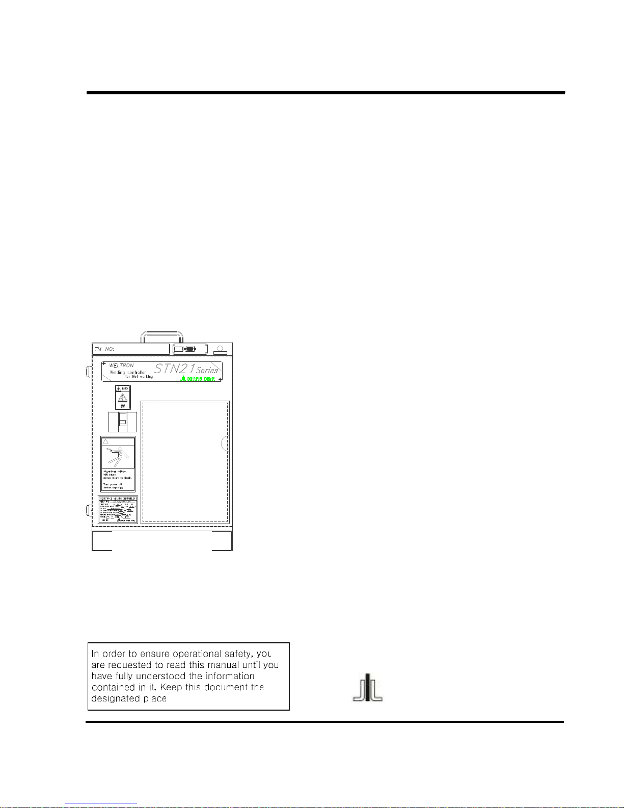
INSTRUCTION MANUAL
Welding Controller
STN21 Series
POWER
TP/DP
Connector
WARRING
!
Welding Condition ChartWelding Condition Chart
OBARA KOREA CORP.

SSSSTN
TNTN
TN21 Series
21 Series21 Series
21 Series
OBARA
OBARA OBARA
OBARA KOREA
KOREAKOREA
KOREA
PAGE 2-
Contents
ContentsContents
Contents
= Safety Guide and Instructi
= Safety Guide and Instructi= Safety Guide and Instructi
= Safety Guide and Instructions =
ons =ons =
ons =.................................................................................................................... 4
1. BASIC SPECIFICATIONS
1. BASIC SPECIFICATIONS1. BASIC SPECIFICATIONS
1. BASIC SPECIFICATIONS ............................................................................................................................ 11
1.1 Model
1.1 Model1.1 Model
1.1 Model................................................................................................................................................ 11
1.2 Control func
1.2 Control func1.2 Control func
1.2 Control functions
tionstions
tions............................................................................................................................... 11
1.3 Inputs and outputs
1.3 Inputs and outputs1.3 Inputs and outputs
1.3 Inputs and outputs ............................................................................................................................ 12
1.4 Dimensions and weight
1.4 Dimensions and weight1.4 Dimensions and weight
1.4 Dimensions and weight..................................................................................................................... 12
1.5 Equipment specifications
1.5 Equipment specifications1.5 Equipment specifications
1.5 Equipment specifications .................................................................................................................. 13
1.6 Accuracy
1.6 Accuracy1.6 Accuracy
1.6 Accuracy........................................................................................................................................... 14
1.7 Paint color
1.7 Paint color1.7 Paint color
1.7 Paint color ........................................................................................................................................ 14
1.8 Power indicator Lamp
1.8 Power indicator Lamp1.8 Power indicator Lamp
1.8 Power indicator Lamp........................................................................................................................ 14
1.9 Connection associated equipment
1.9 Connection associated equipment1.9 Connection associated equipment
1.9 Connection associated equipment .................................................................................................... 14
2. INSTALLATION AND CONNECTIONS
2. INSTALLATION AND CONNECTIONS2. INSTALLATION AND CONNECTIONS
2. INSTALLATION AND CONNECTIONS .......................................................................................................... 15
2.1 Installation
2.1 Installation2.1 Installation
2.1 Installation ........................................................................................................................................ 15
2.2
2.2 2.2
2.2 Connections
ConnectionsConnections
Connections (
( (
(power, welding, transformer and cooling water)
power, welding, transformer and cooling water)power, welding, transformer and cooling water)
power, welding, transformer and cooling water) .......................................................... 16
2.3 Grounding wire
2.3 Grounding wire2.3 Grounding wire
2.3 Grounding wire.................................................................................................................................. 17
2.4 Connection of the PN/C cable
2.4 Connection of the PN/C cable2.4 Connection of the PN/C cable
2.4 Connection of the PN/C cable........................................................................................................... 18
2.5 Connection of the control wires
2.5 Connection of the control wires2.5 Connection of the control wires
2.5 Connection of the control wires......................................................................................................... 19
2.6 TB1 Input / Output for Parameter setting “Remote I/O: ON”
2.6 TB1 Input / Output for Parameter setting “Remote I/O: ON”2.6 TB1 Input / Output for Parameter setting “Remote I/O: ON”
2.6 TB1 Input / Output for Parameter setting “Remote I/O: ON”.............................................................. 22
2.7 Inputting Start Signal and Instructions
2.7 Inputting Start Signal and Instructions2.7 Inputting Start Signal and Instructions
2.7 Inputting Start Signal and Instructions ............................................................................................... 23
2.8 Step Clear
2.8 Step Clear2.8 Step Clear
2.8 Step Clear ......................................................................................................................................... 24
2.9 Step Select Clear
2.9 Step Select Clear2.9 Step Select Clear
2.9 Step Select Clear .............................................................................................................................. 24
3. INITIAL POWER
3. INITIAL POWER3. INITIAL POWER
3. INITIAL POWER----ON PRECAUTIONS
ON PRECAUTIONSON PRECAUTIONS
ON PRECAUTIONS ........................................................................................................... 25
3.1 Check items before power
3.1 Check items before power3.1 Check items before power
3.1 Check items before power----on
onon
on........................................................................................................... 25
3.2 Check items at power
3.2 Check items at power3.2 Check items at power
3.2 Check items at power----on
onon
on.................................................................................................................. 25
3.3 Emergency stop
3.3 Emergency stop3.3 Emergency stop
3.3 Emergency stop ................................................................................................................................ 25
4. TP
4. TP4. TP
4. TP----NET OPERATION
NET OPERATIONNET OPERATION
NET OPERATION.................................................................................................................................. 26
4.1 Names and functions of controls
4.1 Names and functions of controls4.1 Names and functions of controls
4.1 Names and functions of controls....................................................................................................... 27
4.2 Notes o
4.2 Notes o4.2 Notes o
4.2 Notes on different modes
n different modesn different modes
n different modes.................................................................................................................. 31
4.3 Operation monitor
4.3 Operation monitor4.3 Operation monitor
4.3 Operation monitor ............................................................................................................................. 32
4.4 Description of the welding conditions
4.4 Description of the welding conditions4.4 Description of the welding conditions
4.4 Description of the welding conditions................................................................................................ 33
4.5 Description of functions related to parameters
4.5 Description of functions related to parameters4.5 Description of functions related to parameters
4.5 Description of functions related to parameters .................................................................................. 37
4.6 Initial operation of the TP
4.6 Initial operation of the TP4.6 Initial operation of the TP
4.6 Initial operation of the TP .................................................................................................................. 45
4.7 Setting
4.7 Setting 4.7 Setting
4.7 Setting and changing parameters
and changing parametersand changing parameters
and changing parameters...................................................................................................... 47
4.8 Setting and changing welding conditions
4.8 Setting and changing welding conditions4.8 Setting and changing welding conditions
4.8 Setting and changing welding conditions .......................................................................................... 49
4.9 Copy and Verify functions for welding conditions
4.9 Copy and Verify functions for welding conditions4.9 Copy and Verify functions for welding conditions
4.9 Copy and Verify functions for welding conditions .............................................................................. 51
4.9.1 Using the FCP
4.9.1 Using the FCP4.9.1 Using the FCP
4.9.1 Using the FCP ......................................................................................................................... 52
4.9.2 Using the series copy function SCP
4.9.2 Using the series copy function SCP4.9.2 Using the series copy function SCP
4.9.2 Using the series copy function SCP......................................................................................... 53
4.9.3 Using the group copy function GCP
4.9.3 Using the group copy function GCP4.9.3 Using the group copy function GCP
4.9.3 Using the group copy function GCP......................................................................................... 54
4.10 Copy and Verify data between the timer and the TP
4.10 Copy and Verify data between the timer and the TP4.10 Copy and Verify data between the timer and the TP
4.10 Copy and Verify data between the timer and the TP......................................................................... 55
4.10.1 T
4.10.1 T 4.10.1 T
4.10.1 T → PPPP.................................................................................................................................... 55
4.10.2 P
4.10.2 P 4.10.2 P
4.10.2 P → TTTT.................................................................................................................................... 56
4.10.3 P
4.10.3 P 4.10.3 P
4.10.3 P → PPPP.................................................................................................................................. 57
4.10.4 T
4.10.4 T 4.10.4 T
4.10.4 T ←→ PPPP................................................................................................................................. 58
4.11 Confirmation of the alarm history
4.11 Confirmation of the alarm history4.11 Confirmation of the alarm history
4.11 Confirmation of the alarm history..................................................................................................... 59

SSSSTN
TNTN
TN21 Series
21 Series21 Series
21 Series
OBARA
OBARA OBARA
OBARA KOREA
KOREAKOREA
KOREA
PAGE 3-
4.12 Gun counter reset
4.12 Gun counter reset4.12 Gun counter reset
4.12 Gun counter reset ........................................................................................................................... 59
4.1
4.14.1
4.13 Step reset
3 Step reset3 Step reset
3 Step reset ....................................................................................................................................... 60
4.14 Step change
4.14 Step change4.14 Step change
4.14 Step change.................................................................................................................................... 60
4.15 Checking the I/O information
4.15 Checking the I/O information4.15 Checking the I/O information
4.15 Checking the I/O information........................................................................................................... 61
4.16 Sequence of basic operation
4.16 Sequence of basic operation4.16 Sequence of basic operation
4.16 Sequence of basic operation........................................................................................................... 63
5. DP
5. DP5. DP
5. DP----NET OPERATION
NET OPERATIONNET OPERATION
NET OPERATION ................................................................................................................................. 64
6. MAINTENANCE
6. MAINTENANCE6. MAINTENANCE
6. MAINTENANCE .......................................................................................................................................... 65
6.1 Precautions for maintenance
6.1 Precautions for maintenance6.1 Precautions for maintenance
6.1 Precautions for maintenance............................................................................................................. 65
7. TROUBLESHOOTING
7. TROUBLESHOOTING7. TROUBLESHOOTING
7. TROUBLESHOOTING ................................................................................................................................. 66
8. ALARMS
8. ALARMS8. ALARMS
8. ALARMS..................................................................................................................................................... 74
8.1 Classification of the alarms
8.1 Classification of the alarms8.1 Classification of the alarms
8.1 Classification of the alarms............................................................................................................... 74
8.2 Settings associated with alarms
8.2 Settings associated with alarms8.2 Settings associated with alarms
8.2 Settings associated with alarms ........................................................................................................ 74
9. INSPECTION
9. INSPECTION9. INSPECTION
9. INSPECTION .............................................................................................................................................. 80
10. STORGE
10. STORGE10. STORGE
10. STORGE .................................................................................................................................................. 82
11. SPECIAL FUNCTIONS
11. SPECIAL FUNCTIONS11. SPECIAL FUNCTIONS
11. SPECIAL FUNCTIONS............................................................................................................................... 83
11.1
11.1 11.1
11.1 Pulse Start
Pulse StartPulse Start
Pulse Start....................................................................................................................................... 83
11.2 Pulsation
11.2 Pulsation11.2 Pulsation
11.2 Pulsation ......................................................................................................................................... 84
11.3 START SW Preferred function
11.3 START SW Preferred function11.3 START SW Preferred function
11.3 START SW Preferred function .......................................................................................................... 84
11.4 Re
11.4 Re11.4 Re
11.4 Re----Weld function
Weld functionWeld function
Weld function............................................................................................................................ 85
11.5 Trans Diode Short
11.5 Trans Diode Short11.5 Trans Diode Short
11.5 Trans Diode Short ........................................................................................................................... 85
11.6 Current Detection function
11.6 Current Detection function11.6 Current Detection function
11.6 Current Detection function............................................................................................................... 86
11111.7 Step Up control
1.7 Step Up control1.7 Step Up control
1.7 Step Up control ............................................................................................................................... 87
11.7.1 Step Up control..................................................................................................................... 87
11.7.2 Setting procedure for using the Step Up function ............................................................. 88
11.7.3 Step All Clear .................................................................................................................... 89
11.7.4 Step Select Clear .............................................................................................................. 89
11.7.5 Step Reset ............................................................................................................................ 89
11.7.6 Step Change ......................................................................................................................... 89
11.8 Linear Up control
11.8 Linear Up control11.8 Linear Up control
11.8 Linear Up control............................................................................................................................. 90
11.8.1 Linear Up control .................................................................................................................. 90
11.8.2 Setting procedure for using the linear Up function................................................................ 90
11.9 Variable Pressure (option)
11.9 Variable Pressure (option)11.9 Variable Pressure (option)
11.9 Variable Pressure (option) ............................................................................................................... 91
11.9.1 Variable Pressure setting....................................................................................................... 91
11.9.2 Variable Pressure sequence.................................................................................................. 92
11.10 Pressure
11.10 Pressure11.10 Pressure
11.10 Pressure Selector
Selector Selector
Selector .......................................................................................................................... 93
11.11 Weld Interlock
11.11 Weld Interlock11.11 Weld Interlock
11.11 Weld Interlock ............................................................................................................................... 94
11.12 No Weld/Conti.Press
11.12 No Weld/Conti.Press11.12 No Weld/Conti.Press
11.12 No Weld/Conti.Press ..................................................................................................................... 95
11.13 Device
11.13 Device11.13 Device
11.13 Device----Net (option)
Net (option)Net (option)
Net (option) ...................................................................................................................... 98
11.14 PLURALITY OF UNIT
11.14 PLURALITY OF UNIT11.14 PLURALITY OF UNIT
11.14 PLURALITY OF UNIT ................................................................................................................ 117
11.14.1 Connection of Plurality of Units......................................................................................... 117
11.14.2 Installation of Plurality of Units.......................................................................................... 117
11.14.3 TP-Net Operation for Installation of Plurality of Units........................................................ 117
11.14.4 Troubleshooting (When Plurality of Units Are Connected) ................................................. 118

SSSSTN
TNTN
TN21 Series
21 Series21 Series
21 Series
OBARA
OBARA OBARA
OBARA KOREA
KOREAKOREA
KOREA
PAGE 4-
=
= =
= Safety Guide and Instructions
Safety Guide and Instructions Safety Guide and Instructions
Safety Guide and Instructions ====
This instruction manual should be thoroughly read for safe and correct
operation of this product.
• In order to ensure safety, only those persons who are qualified or well versed in welding
machines shall be engaged in installation, maintenance and repairs.
• The operator of the equipment shall thoroughly understand the information contained in
this manual, have sufficient technical knowledge, and be able to perform safety
operation.
• As far as safety education is concerned, it is recommended that those concerned
participate in various kinds of seminars and take qualification tests conducted under the
auspices of the Welding Academy, Welding Association, and related organizations. Also,
the owner is requested to educated the personnel in safety whenever considered
necessary.
• Keep this manual at a place to which operators have easy access and leaf it through as
many times as required.
• For further information, contact any of your local dealers whose phones and fax numbers
are listed below.
Manufacturer
ManufacturerManufacturer
Manufacturer
OBARA KOREA CORP
OBARA KOREA CORPOBARA KOREA CORP
OBARA KOREA CORP
Head Office
Head Office Head Office
Head Office
555535
3535
35----158, Kasan
158, Kasan158, Kasan
158, Kasan----Dong, Keumchun
Dong, KeumchunDong, Keumchun
Dong, Keumchun----Ku,
Ku,Ku,
Ku,
Seo
SeoSeo
Seoul, Korea (153
ul, Korea (153ul, Korea (153
ul, Korea (153----803)
803)803)
803)
TEL
TELTEL
TEL
(02) 867
(02) 867(02) 867
(02) 867----0171
01710171
0171
FAX
FAX FAX
FAX
(02) 867
(02) 867 (02) 867
(02) 867----6531
65316531
6531
SSSSTN
TNTN
TN21 Series
21 Series21 Series
21 Series
OBARA
OBARA OBARA
OBARA KOREA
KOREAKOREA
KOREA
PAGE 5-
=
= =
= Safety Precautions
Safety PrecautionsSafety Precautions
Safety Precautions =
= =
=
Before starting operation, thoroughly read this manual for safe and correct operation of this product.
•
Precautions described in this manual are intended to ensure safe operation of the equipment and preclude
the possibility of incurring injury to you and your co-workers.
•
This product is designed and fabricated in due consideration of safety. However, it is essential that the
precautions in this manual be taken. Failure to take such precautions may cause a fatal or serious injury.
•
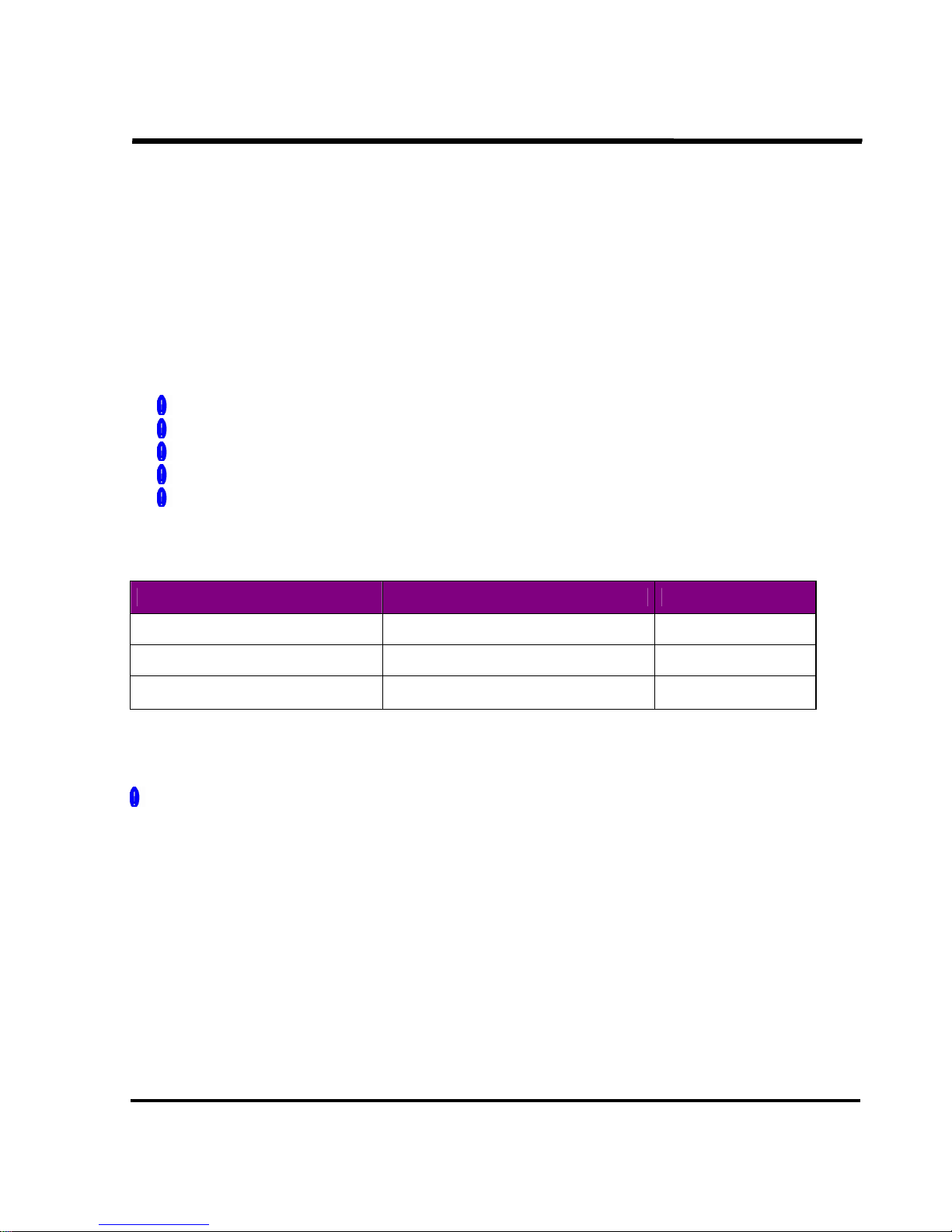
Incorrect operation of the equipment may cause different levels of hazards and damage. This instruction
manual classifies these levels into the following two, which are represented by the corresponding symbols
and terms and used to warn the operator against possible hazards and damage. These symbols and terms
are also used in like manner on the warning labels affixed to the equipment.
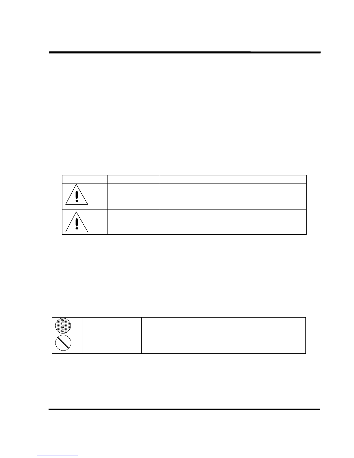
Symbol Term Description
DANGER
DANGERDANGER
DANGER
Incorrect operation can cause hazardous condition
which could result in a fatal or serious injury.
CAUTION
CAUTIONCAUTION
CAUTION
Incorrect operation can cause hazardous condition
which could result in a slight injury and which may only
cause property damage.
※ Symbols apply to general cases of the operation.
The term serious injury means loss of sight, wound, burns (resulting from too high or low an ambient
temperature), electric shock, fractures or poisoning that has aftereffects and requires medical treatment,
hospitalization or seeing the physician for long periods as an outpatient.
The term slight injury means wound, burns or electric shock that does not require medical treatment,
hospitalization or long-term treatment as an outpatient.
The term property damage means breakage of the property or consequential damage to the equipment.
As far as the handling of equipment is concerned, the matters related to “must” and “must not”
are indicated below.
COMPULSORY
COMPULSORYCOMPULSORY
COMPULSORY
Must: e.g.., grounding connection
PROHIBITED
PROHIBITEDPROHIBITED
PROHIBITED
Must not
※ Symbols apply to general cases of the operation.
SSSSTN
TNTN
TN21 Series
21 Series21 Series
21 Series
OBARA
OBARA OBARA
OBARA KOREA
KOREAKOREA
KOREA
PAGE 6-
Discouragement of operation by Certain Operators
Discouragement of operation by Certain OperatorsDiscouragement of operation by Certain Operators
Discouragement of operation by Certain Operators
For operational safety, discourage the following persons from performing operation:
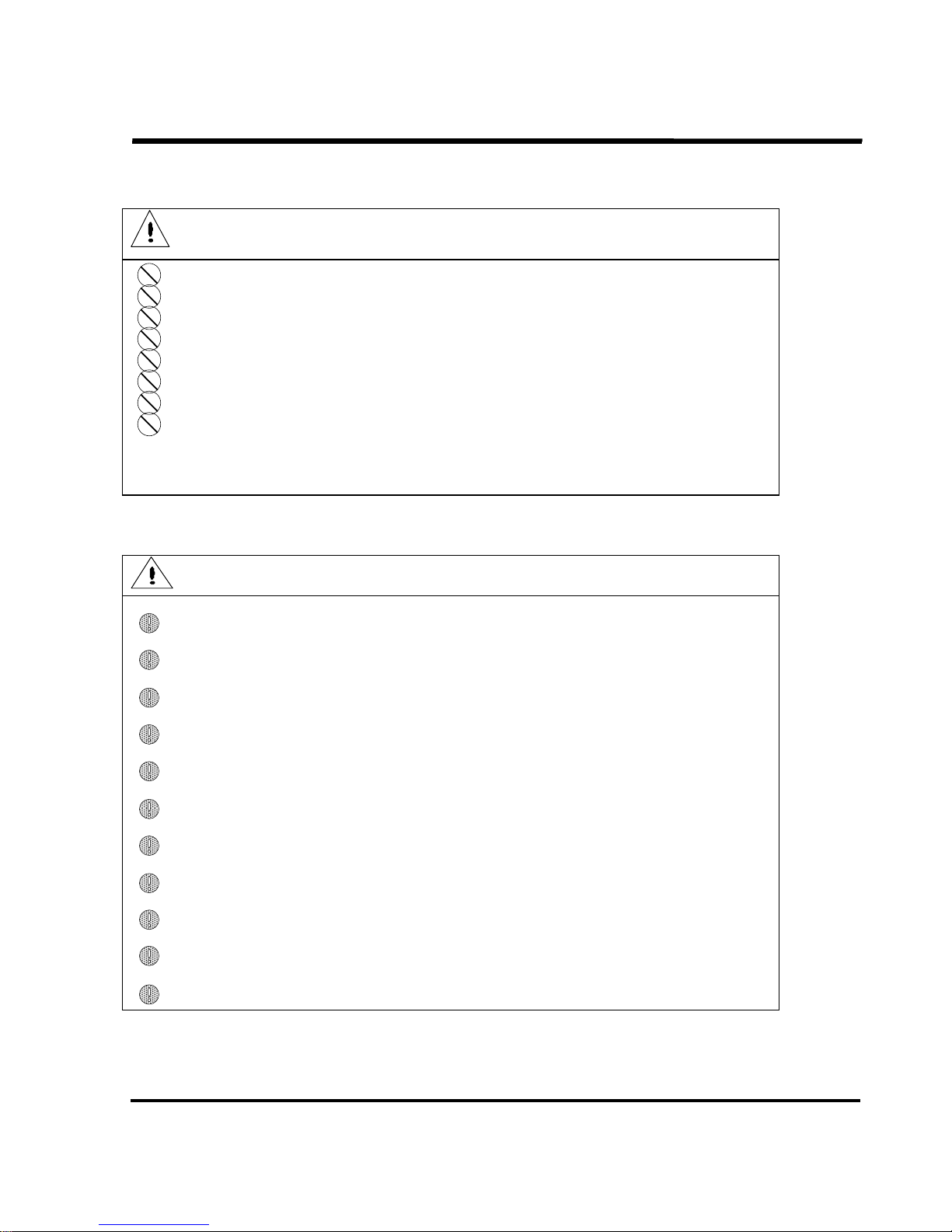
DANGER
DANGERDANGER
DANGER
Mentally-troubled person.
Physically handicapped person who is hard to operate the equipment.
Addicted to drugs.
Intoxicated.
With a pacemaker implanted.
Without protective gears on.
Not having undergone appropriate education or guidance and technically unqualified.
With a long hair not bundled.
Education in Safety
Education in SafetyEducation in Safety
Education in Safety
The operator must not operate the equipment unless he or she:
CAUTION
CAUTIONCAUTION
CAUTION
Understands the information contained in this manual.
Understands the meaning of symbols and terms on the warning labels.
Has knowledge of Learning heart massage and artificial respiration (CPR).
Is capable of checking the protective equipment such as fire clothes.
Knows the point of contact in an emergency.
Has knowledge of first aid treatment for burns and injuries and the location of first aid kit.
Has knowledge of the location and resetting method of the Emergency Stop switch.
Is capable of inspecting the equipment.
Has knowledge of electricity.
Understands the equipment and knows it’s wiring connections and voltage value; and.
Has knowledge of resistance welding.

SSSSTN
TNTN
TN21 Series
21 Series21 Series
21 Series
OBARA
OBARA OBARA
OBARA KOREA
KOREAKOREA
KOREA
PAGE 7-
Safety Precautions to Be Taken
Safety Precautions to Be TakenSafety Precautions to Be Taken
Safety Precautions to Be Taken
DANGER
DANGERDANGER
DANGER
To avoid accidents resulting in a serious or fatal injury, be sure to observe
the following:
1. This welding machine is designed and fabricated, giving due consideration to safety. However, it is
essential that the precautions stated in this manual be taken. Failure to take such precautions may
cause a fatal or serious injury.
2. Jobs related to the I/O power source; determination of the installation site; handling, storage and
piping of high pressure gas; storage of products after welding; and disposal of wastes should be
done according to the local regulations as well as your in-house standard.
3. Do not allow unauthorized persons to approach the welding machine or the workplace.
4. Do not allow a person with a pacemaker embedded in his or her body to approach the welding
machine or the workplace without the approval from the physician. Since the welding machine
creates magnetic field around it during operation, it can adversely affect the pacemaker.
5. For ensuring safety, the welding machine should be installed, serviced, and repaired by only qualified
personnel or those who are familiar with it.
6. Also for ensuring safety, the welding machine should be operated by those who fully understand the
information contained in this instruction manual and have knowledge and skills of safe operation.
7. Do not use the welding machine for any other purposes than welding.
SSSSTN
TNTN
TN21 Series
21 Series21 Series
21 Series
OBARA
OBARA OBARA
OBARA KOREA
KOREAKOREA
KOREA
PAGE 8-
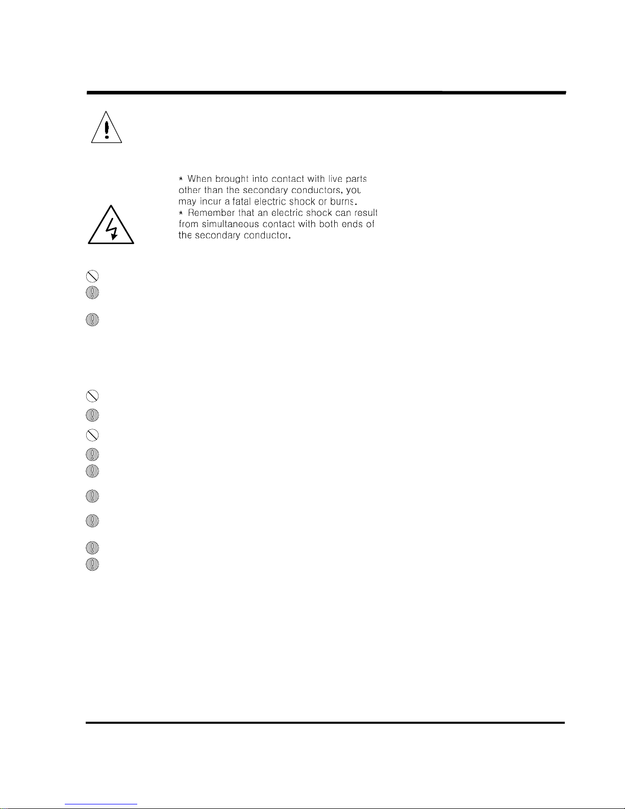
DANGER
DANGERDANGER
DANGER
To avoid an electric shock, be sure to observe the following:
1. Do not attempt to touch live parts other than the secondary conductors.
2. Refer grounding of the welding machine to a certified electrician or other qualified person in
accordance with the regulations (Electrical Equipment Technical Standard).
3. When replacing a circuit board, fuse, or other parts or in cases where accidental contact with other
high-voltage parts is probable, be sure to turn off the main circuit breaker and make sure that a lit
charge lamp begins to dim and finally goes out.
Make sure that the charge lamp remains unlit. Using a tester, also make sure that the unit is free of
high voltage. Do not start installation or maintenance until it is certain that the unit is not charged
with power.
4. Do not use damaged cables or those which have insufficient capacity or exposed conductors.
5. Ensure that cable connections are tightened and properly insulated.
6. Do not operate the welding machine with its casing or cover removed.
7. Avoid using a torn or wet pair of gloves. Always use dry, insulated gloves.
8.
Perform inspection and maintenance periodically. Do not re-use the equipment until damaged
portions, if any, have been properly repaired.
9. Cooling water to be used should have an electric resistance of not less than 5000Ω-CM and be free
of sediments.
10. Electric cables and air and water hoses to be used should be sturdy enough to withstand the
specified load and pressure.
11. When the tip changer is put out of use, the related equipment should be powered off.
12. Do not leave the doors of all units open unless they must be opened for inspection or maintenance
service. Keep the doors locked during operation. Ask the responsible person for strict storage of
keys.
SSSSTN
TNTN
TN21 Series
21 Series21 Series
21 Series
OBARA
OBARA OBARA
OBARA KOREA
KOREAKOREA
KOREA
PAGE 9-
DANGER
DANGERDANGER
DANGER
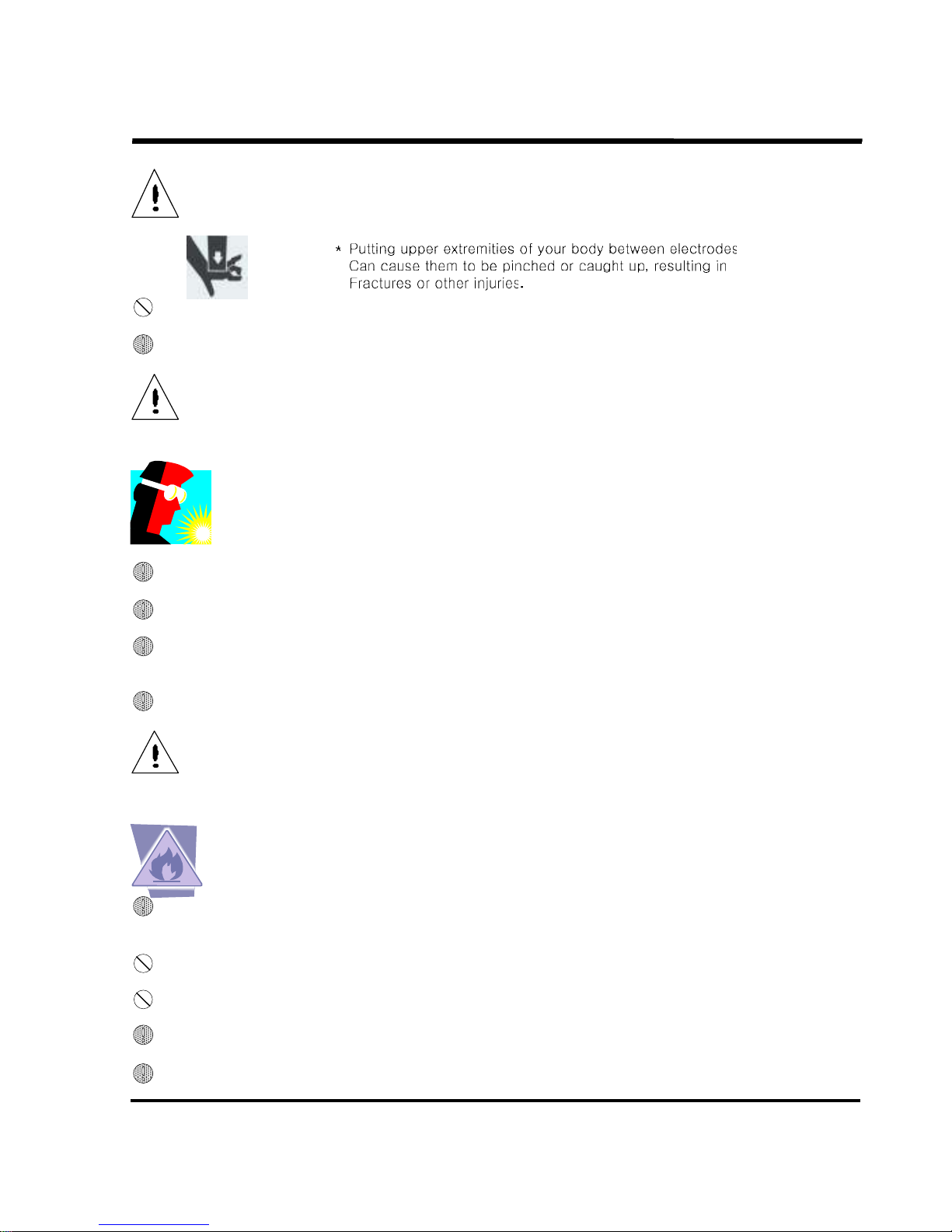
Do not try to put your fingers or hand between electrodes.
1. Do not try to put your fingers, hand or arm between electrodes.
2. Before turning on the power (for solenoid valves) or supplying compressed air, ensure safety around
the welding machine.
CAUTION
CAUTIONCAUTION
CAUTION
Use protective gears to protect you and your co-workers from splashes or
spatters that are generated during welding job.
* Chips scattered will cause injury to the eyes or bums.
* Too loud a noise may cause hardness of hearing.
1. Wear safety goggles to protect the eyes from scattering chips.
2. Wear protective gears, including protective gloves, clothes with long sleeves and leather apron.
3. Install a protective curtain around the area surrounding the welding work site so that splashes
and spatter are not projected towards other people.
4. Wear a sound-proof gear if noise is too loud.
CAUTION
CAUTIONCAUTION
CAUTION
To prevent a fire or an explosion, be sure to observe the following.
* Spatters from welding as well as base metal that is hot
immediately after welding can cause a fire.
* Overheat that is caused by loose cable connections during
current application can also start a fire.
1. Keep the job site clean of combustibles which easily ignite when brought into contact with spatters.
If they cannot be removed, cover them with a sheet of nonflammable material.
2. Do not use the tip changer near the area where there are combustible gases.
3. Keep hot base metal away from combustibles.
4. Ensure that the cable connections are tightened and properly insulated.
5. Provide an extinguisher near the welding site in case of an emergency.
SSSSTN
TNTN
TN21 Series
21 Series21 Series
21 Series
OBARA
OBARA OBARA
OBARA KOREA
KOREAKOREA
KOREA
PAGE 10-
=
= =
= Indication of hazardous zone
Indication of hazardous zoneIndication of hazardous zone
Indication of hazardous zone =
= =
=
=
= =
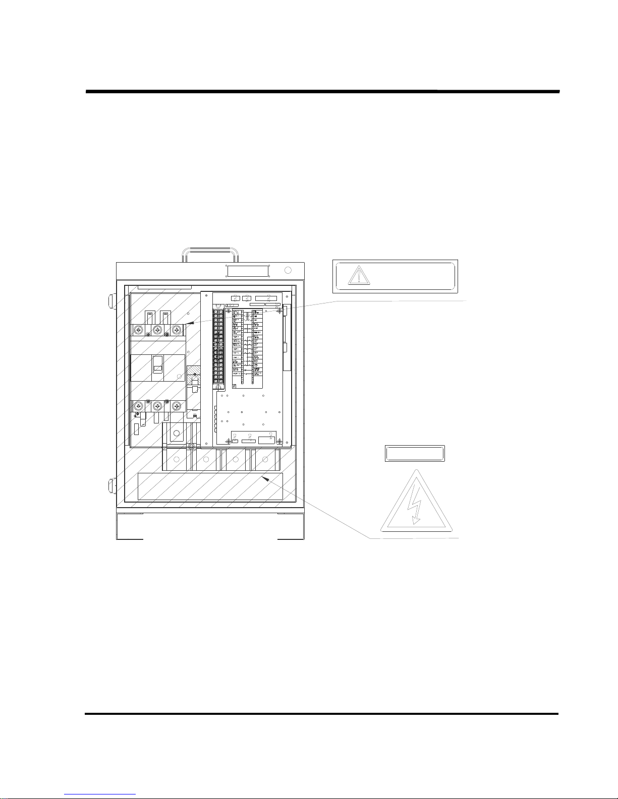
= Type and location of warning label
Type and location of warning labelType and location of warning label
Type and location of warning label =
= =
=
P2
CP2
ZR1
CR3
Warning labels
DANGER
The shaded areas in the
figures show the high-voltage
hazardous areas of the
equipment.

SSSSTN
TNTN
TN21 Series
21 Series21 Series
21 Series
OBARA
OBARA OBARA
OBARA KOREA
KOREAKOREA
KOREA
PAGE 11-
1.
1. 1.
1. BASIC SPECIFICATIONS
BASIC SPECIFICATIONSBASIC SPECIFICATIONS
BASIC SPECIFICATIONS
1.1
1.1 1.1
1.1 Model
ModelModel
Model
SSSSTN
TNTN
TN21
2121
21Y Series
Y SeriesY Series
Y Series
1.2
1.2 1.2
1.2 Control functions
Control functionsControl functions
Control functions
Control method
Control methodControl method
Control method
All digital control, synchronous type
Control series
Control seriesControl series
Control series
4 series/15 series/16 groups; Maximum control series: 240 conditions
Up to 8 guns (counter/Step Up control), or Up to 4 guns (solenoid control)
(combination of 2 guns and 2 retract guns can be controlled.)
Setting method
Setting methodSetting method
Setting method
Remote setting method
Time control
Time controlTime control
Time control
Squeeze Delay Time
Squeeze Time
Slope Time
Weld Time 1
Cool Time 1
Weld Time 2
Down Slope Time
Cool Time 2
Weld Time 3
Hold Time
Off Time
Pressure Rise Time 1
Pressure Rise Time 2
Pressure Rise Time 3
Hold End Delay Time
Cyclic control
Cyclic controlCyclic control
Cyclic control
Pulsation 1 ~ 9 (for all series)
Re-Conduction Count 1 (selectable using the parameter)
Current control
Current controlCurrent control
Current control
Constant current control method Primary current feedback by the CT
Current settings
Current settingsCurrent settings
Current settings
Direct setting 2000A to 60000A (in 100A step)
Primary current setting 50 to 1500A (There is the restriction with duty)
Stepping control
Stepping controlStepping control
Stepping control
Step Up system (up to 16 steps)
Maximum spot count: 9999
1.
1.1.
1.
BASIC
BASICBASIC
BASIC
2.
2.2.
2.
INSTALLATION
INSTALLATIONINSTALLATION
INSTALLATION
3.
3.3.
3.
POWER
POWERPOWER
POWER
4.
4.4.
4.
TP
TPTP
TP
5.
5.5.
5.
DP
DPDP
DP
6.
6.6.
6.
MAINTENANCE
MAINTENANCEMAINTENANCE
MAINTENANCE
7.
7.7.
7.
TROUBLE
TROUBLETROUBLE
TROUBLE
8.
8.8.
8.
ALARMS
ALARMSALARMS
ALARMS
9.
9.9.
9.
INSPECTION
INSPECTIONINSPECTION
INSPECTION
10.
10.10.
10.
STORAGE
STORAGESTORAGE
STORAGE
11.
11.11.
11.
SPEC
SPECSPEC
SPECIAL
IALIAL
IAL
0 to 99 cyc (for all series)
1 to 99 cyc (for all series)
1 to 30 cyc (for all series)
0 to 99 cyc (for all series)
0 to 99 cyc (for all series)
0 to 99 cyc (for all series)
0 to 99 cyc (for all series)
0 to 99 cyc (for all series)
0 to 99 cyc (for all series)
1 to 99 cyc (for all series)
4 to 99 cyc (for all series)
0 to 99 cyc (for all series)
0 to 99 cyc (for all series)
0 to 99 cyc (for all series)
0 to 99 cyc (for all series)

SSSSTN
TNTN
TN21 Series
21 Series21 Series
21 Series
OBARA
OBARA OBARA
OBARA KOREA
KOREAKOREA
KOREA
PAGE 12-
1.3
1.31.3
1.3 Inputs and outputs
Inputs and outputsInputs and outputs
Inputs and outputs
Specifications for the solenoid valve
Specifications for the solenoid valveSpecifications for the solenoid valve
Specifications for the solenoid valve
24 VDC
Rated current: 0.5A or less
(The total current of valve outputs should be 0.8A or less)
(A surge absorber must be provided on the solenoid valve side.)
Specifi
SpecifiSpecifi
Specifications for the control terminal block TB1
cations for the control terminal block TB1cations for the control terminal block TB1
cations for the control terminal block TB1
[Input]
Starting input
1N.O×4series (Internal: 24VDC, Input current: 20mA)
or 4N.O×1series (Internal: 24VDC, Input current: 20mA)
Group input 4N.O×1series (Internal: 24VDC, Input current: 20mA)
Retract Starting input 1N.O×2series (Internal: 24VDC, Input current: 20mA)
Step Select Clear input 1N.O×1series (Internal: 24VDC, Input current: 20mA)
Step All clear input 1N.O×1series (Internal: 24VDC, Input current: 20mA)
Alarm Reset input 1N.O×1series (Internal: 24VDC, Input current: 20mA)
Welding On/Off Switch input 1N.O×1series (Internal: 24VDC, Input current: 20mA)
Safety Switch input 1N.O×1series (Internal: 24VDC, Input current: 20mA)
Transformer Thermo input 1N.O×1series (Internal: 24VDC, Input current: 20mA)
[Output]
Hold End output 1 N.O×1series (24VDC, Max current: 0.12A)
Alarm output 1 N.O/N.C×1series (24VDC, Max current: 0.12A)
Last Step output 1 N.O×1series (24VDC, Max current: 0.12A)
(Current Detection signal output)*
Step Completion signal 1 N.O×1series (24VDC, Max current: 0.12A)
*1: When the parameter “Pr CurDetect” is ON, the Last Step signal output changes to the
Conduction Detect signal output. See Section “4.5 Description of parameter functions”
for details.
*2: When the Device Net is used, there are some more inputs and outputs. See Section
“11.15 Device Net” for details.
1.4
1.4 1.4
1.4 Dimensions and weight
Dimensions and weightDimensions and weight
Dimensions and weight
Dimensions Timer main unit: 350 (W) × 245 (D) × 520 (H)
Weight 19 Kg

SSSSTN
TNTN
TN21 Series
21 Series21 Series
21 Series
OBARA
OBARA OBARA
OBARA KOREA
KOREAKOREA
KOREA
PAGE 13-
1.5
1.5 1.5
1.5 Equipment specificati
Equipment specificatiEquipment specificati
Equipment specifications
onsons
ons
Welding power Single-phase, 200/220/380/400/420/440 VAC, 50/60Hz
(Selected by switching the range on the base voltage.)
Applicable voltage is ±20% of the preset voltage.
Power consumption 50 VA (not in weld)
Frequency 50 to 60 Hz (automatically selected on power-on)
Ambient temperature 0 ~ 50°C
Relative humidity 90% max (No condensation)
Cooling system 30°C max
Flow rate 6L/min
Masimum water pressure 0.3 MPa max.
Electric resistance 5000 Ω cm max.
SCR Insulated molding SCR ( SIZE : 717A, D type)
Storage period for setup data 10 년 (setting data)
CAUTION
CAUTIONCAUTION
CAUTION
Handling of the setup data
Handling of the setup dataHandling of the setup data
Handling of the setup data
The storage period for the setup data is 10 years when the main unit is used in
normal condition.
This period does not apply if any faults occur to the main board for some reason.
Therefore, the user is requested to ensure that important data on welding conditions
is stored and
managed at the user side independently of storage of the data in this
equipment.
SSSSTN
TNTN
TN21 Series
21 Series21 Series
21 Series
OBARA
OBARA OBARA
OBARA KOREA
KOREAKOREA
KOREA
PAGE 14-
1.6
1.61.6
1.6 Accuracy
Accuracy Accuracy
Accuracy
Welding power voltage fluctuations ±10% or less
Resistance load fluctuations ±10% or less
Setting accuracy ±3% (with respect to the full scale)
Repeatability ±3% (with respect to the full scale)
1.7
1.7 1.7
1.7 Paint color
Paint colorPaint color
Paint color
Paint color of housing Orange (Equivalent to the color number of E5-259)
Source Standard print color sample card
(1956 edition issued by the Japan Paint Industry Association)
1.8
1.8 1.8
1.8 Power indicator Lamp
Power indicator LampPower indicator Lamp
Power indicator Lamp
Indication color Green or White
Indication condition ON when the Power ON
(24VDC for Internal control is ON)
1.
1.1.
1.9999 Connection associated equipment
Connection associated equipmentConnection associated equipment
Connection associated equipment
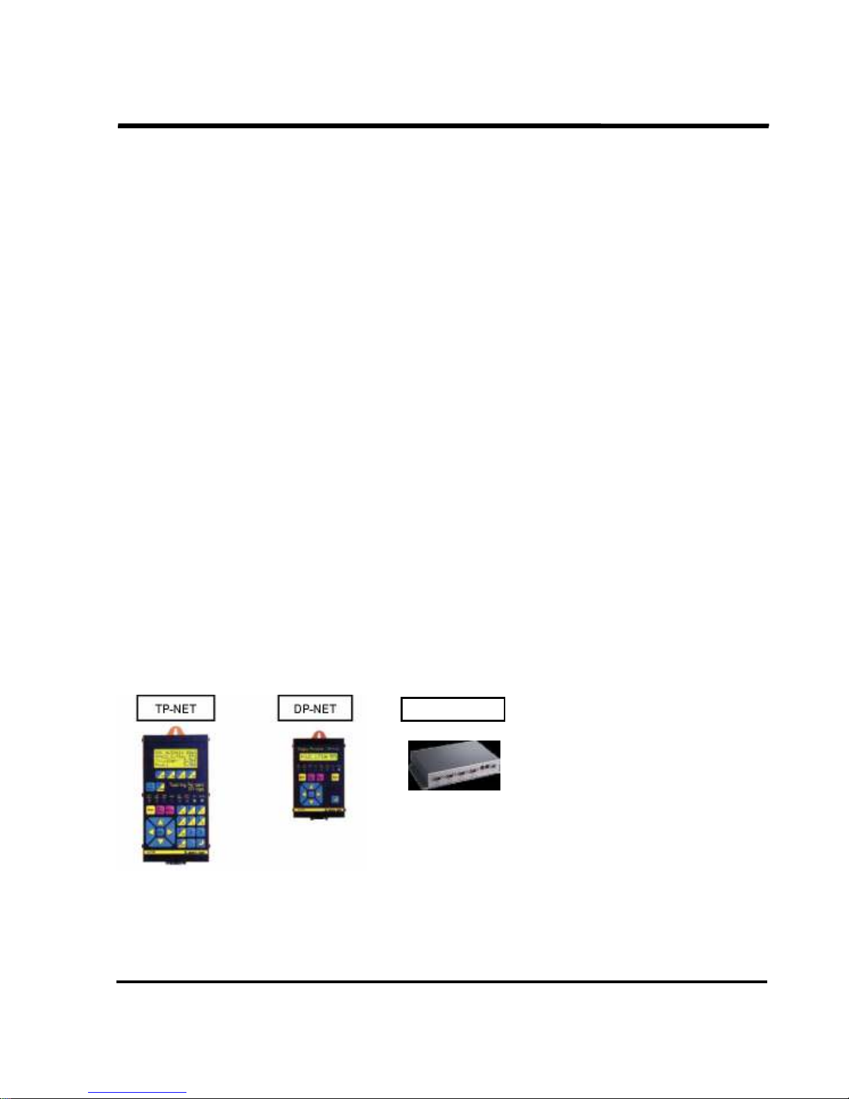
This equipment has the following connection associated equipment.
TP-NET
For welding condition data input + Welding monitor +
Alarm and other indications
DP-NET
Welding result monitor + Welding condition display +
Alarm and other indications
PN/C (pendent cable)
PJ/C (timer cable)
TP-NET / DP-NET / SNS connection cable
Cable to connect timers.(Used for multi-unit setting option)
SMART-NET Allows the welding conditions to be managed by a PC.
SSSSTN
TNTN
TN21 Series
21 Series21 Series
21 Series
OBARA
OBARA OBARA
OBARA KOREA
KOREAKOREA
KOREA
PAGE 15-
2.
2. 2.
2. INSTALLATION AND CONNECTIONS
INSTALLATION AND CONNECTIONSINSTALLATION AND CONNECTIONS
INSTALLATION AND CONNECTIONS
2.1
2.1 2.1
2.1 Installation
InstallationInstallation
Installation
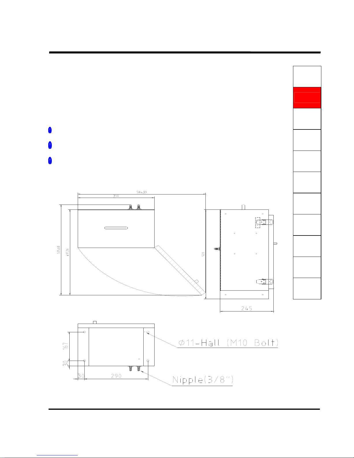
(1) Weight 19Kg
(2) Dimensions 584mm (W) X 497mm (D) X 520mm (H)
584mm (W) X 525mm (D) X 520mm (H)
(3) Use the mounting holes (Φ11mm x 4 places) in the bottom of the main unit.
––
––––
–– Precautions for installation
Precautions for installationPrecautions for installation
Precautions for installation ––
––––
––
Install the controller in a place where the ambient temperature is 0 to 40°C and it is not
exposed to direct sunlight.
Power receiving equipment that feeds the controller should be protected against lightning
according to the local regulations.
Avoid places where the unit is exposed to water splashes, oil drips or dust containing
metallic particles.
- Space Requirement • Mainframe Bottom-side View -
1.
1.1.
1.
BASIC
BASICBASIC
BASIC
2.
2.2.
2.
INSTALLATION
INSTALLATIONINSTALLATION
INSTALLATION
3.
3.3.
3.
POWER
POWERPOWER
POWER
4.
4.4.
4.
TP
TPTP
TP
5.
5.5.
5.
DP
DPDP
DP
6.
6.6.
6.
MAINTENANCE
MAINTENANCEMAINTENANCE
MAINTENANCE
7.
7.7.
7.
TROUBLE
TROUBLETROUBLE
TROUBLE
8.
8.8.
8.
ALARMS
ALARMSALARMS
ALARMS
9.
9.9.
9.
INSPECTION
INSPECTIONINSPECTION
INSPECTION
10.
10.10.
10.
STORAGE
STORAGESTORAGE
STORAGE
11.
11.11.
11.
SPECIAL
SPECIALSPECIAL
SPECIAL
SSSSTN
TNTN
TN21 Series
21 Series21 Series
21 Series
OBARA
OBARA OBARA
OBARA KOREA
KOREAKOREA
KOREA
PAGE 16-
2.2
2.2 2.2
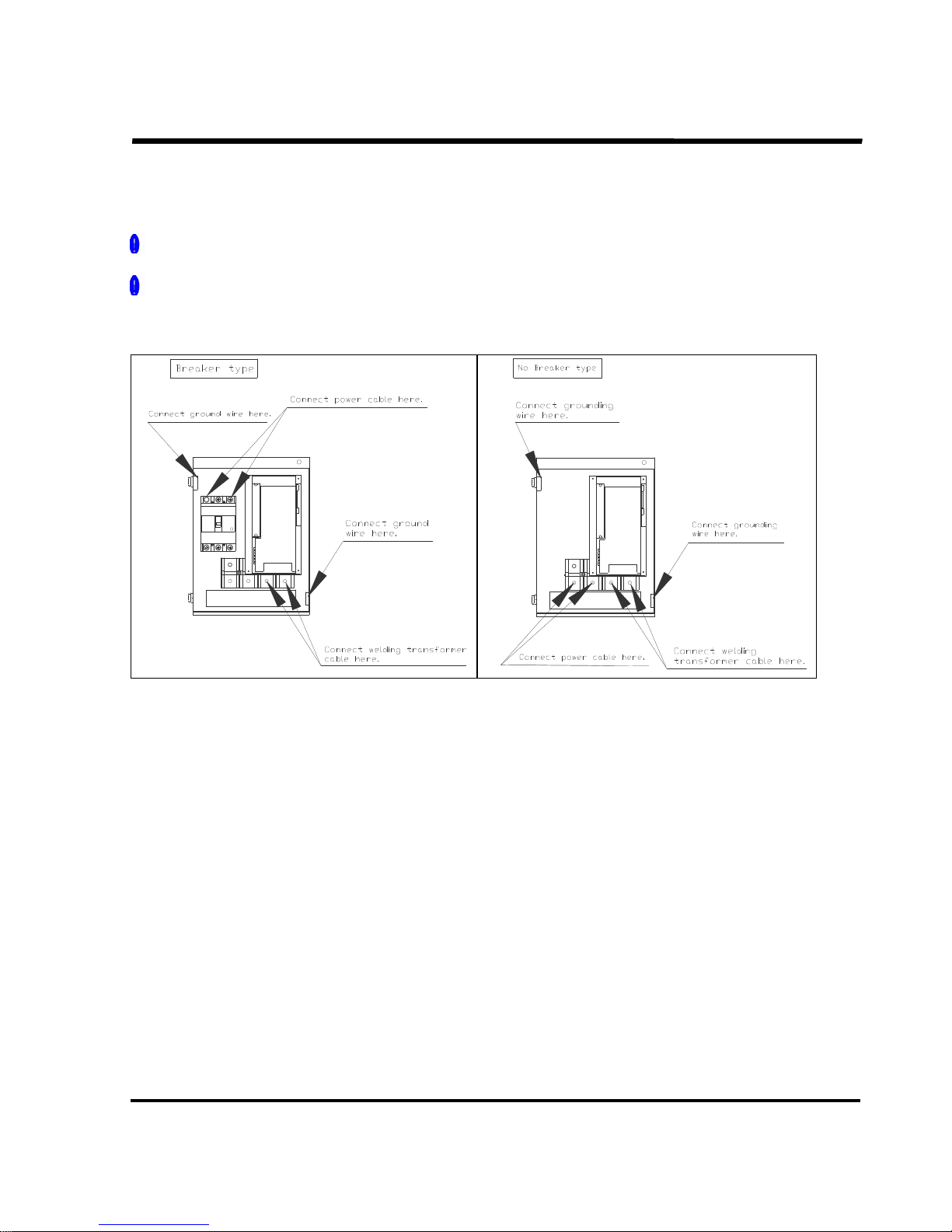
2.2 Connections
ConnectionsConnections
Connections (
( (
(power, welding, transformer and cooling water
power, welding, transformer and cooling waterpower, welding, transformer and cooling water
power, welding, transformer and cooling water))))
Power cable
: Connect it to "01-02" of the power connection terminal at the
bottom of the controller.
Power transformer cable
: Connect it to "01-03" of the power connection terminal at the
bottom of the controller.
Cooling water supply and drain lines
: Connect them to INLET and OUTLET on the left side of the
main unit.
––
––––
–– Precaution for connections
Precaution for connectionsPrecaution for connections
Precaution for connections ––
––––
––
Connection Cable
: 100 mm2 or larger in size (Refer to the following diagram.)
Withstand voltage
: 600VAC or more
Power drop during conduction
: Should be within 20% of the rated voltage
Welding power
: Be sure to install a fuse in the main power connection.
Breaker
: Install a high-frequency proof earth leakage breaker that can
protect the human body on the power supply side of the
controller in use.
Capacity of welding transformer NFB Rated Current (AC380 to 440V) Cable size
35 - 55 kVA 100A 38mm2 or more
- 125 kVA 225A 60mm2 or more
- 180 kVA 350A(400A frame) 100mm2 or more
Note: Any Cable breaker that cannot deal with high frequencies will not protect the
human body. (When in doubt, contact us.)
Cooling water : Use city water or industrial water. Do not use cooling water that contains
electrolytes such as salt.
Circulated cooling water should be entirely changed twice a month or
5 to 10% of the total volume should be replaced continually (because
of condensation by evaporation). Where water is frozen in winter
season in your location, be sure to drain water before putting the unit
out of service.
SSSSTN
TNTN
TN21 Series
21 Series21 Series
21 Series
OBARA
OBARA OBARA
OBARA KOREA
KOREAKOREA
KOREA
PAGE 17-
2.3
2.3 2.3
2.3 Grounding wire
Grounding wireGrounding wire
Grounding wire
Grounding wire : Connect it to the “grounding connection terminal” in the lower part of the controller.
(Refer to the following diagram.)
Connection cable : 50mm2 or larger in size (Larger than half the size of the power cable.)
POWER
POWER
SSSSTN
TNTN
TN21 Series
21 Series21 Series
21 Series
OBARA
OBARA OBARA
OBARA KOREA
KOREAKOREA
KOREA
PAGE 18-
2.4
2.4 2.4
2.4 Connection of the PN/C cable
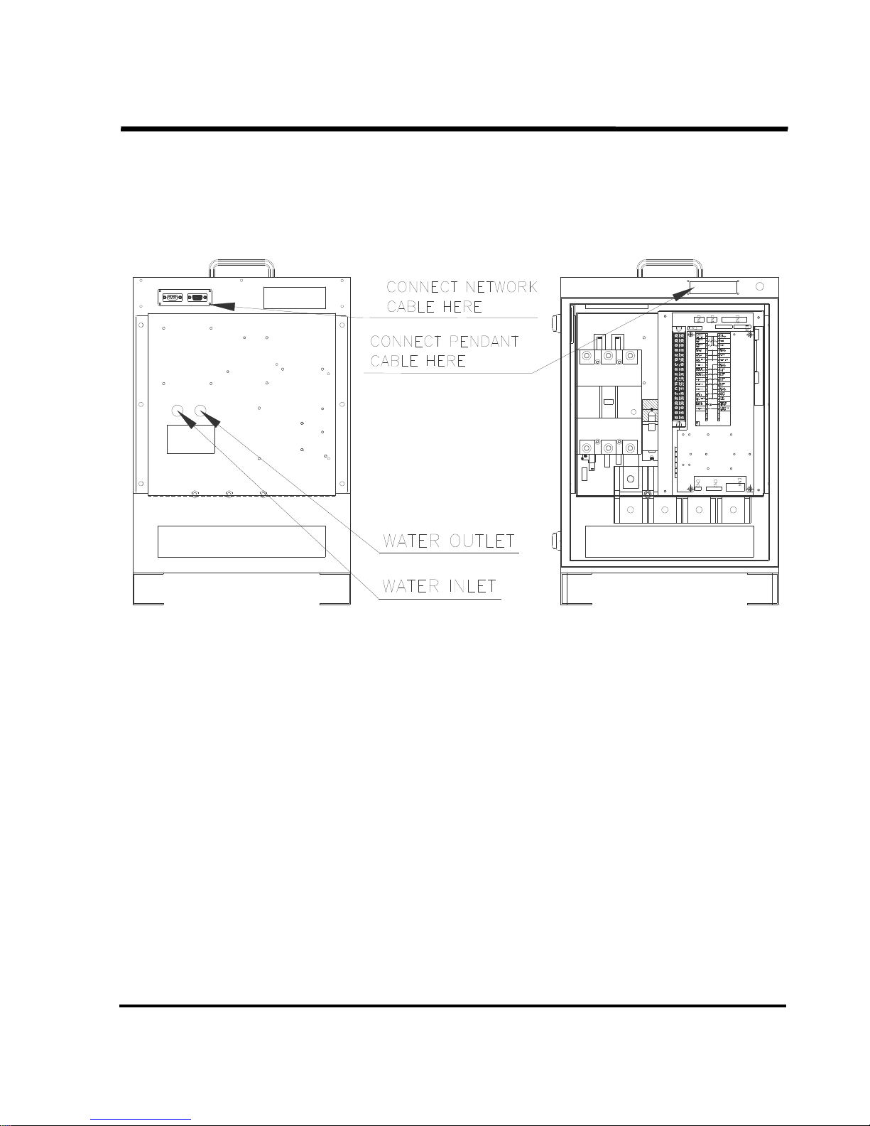
Connection of the PN/C cableConnection of the PN/C cable
Connection of the PN/C cable
Connect the PN/C (TP-NET / DP-NET / SNS) cable to the TP connector of the timer main unit.
CR3
ZR1
CP2
P2
INLET
OUTLET
WaterFlowlate : 4.5L / Min
Water : 30 'C

SSSSTN
TNTN
TN21 Series
21 Series21 Series
21 Series
OBARA
OBARA OBARA
OBARA KOREA
KOREAKOREA
KOREA
PAGE 19-
2.5
2.5 2.5
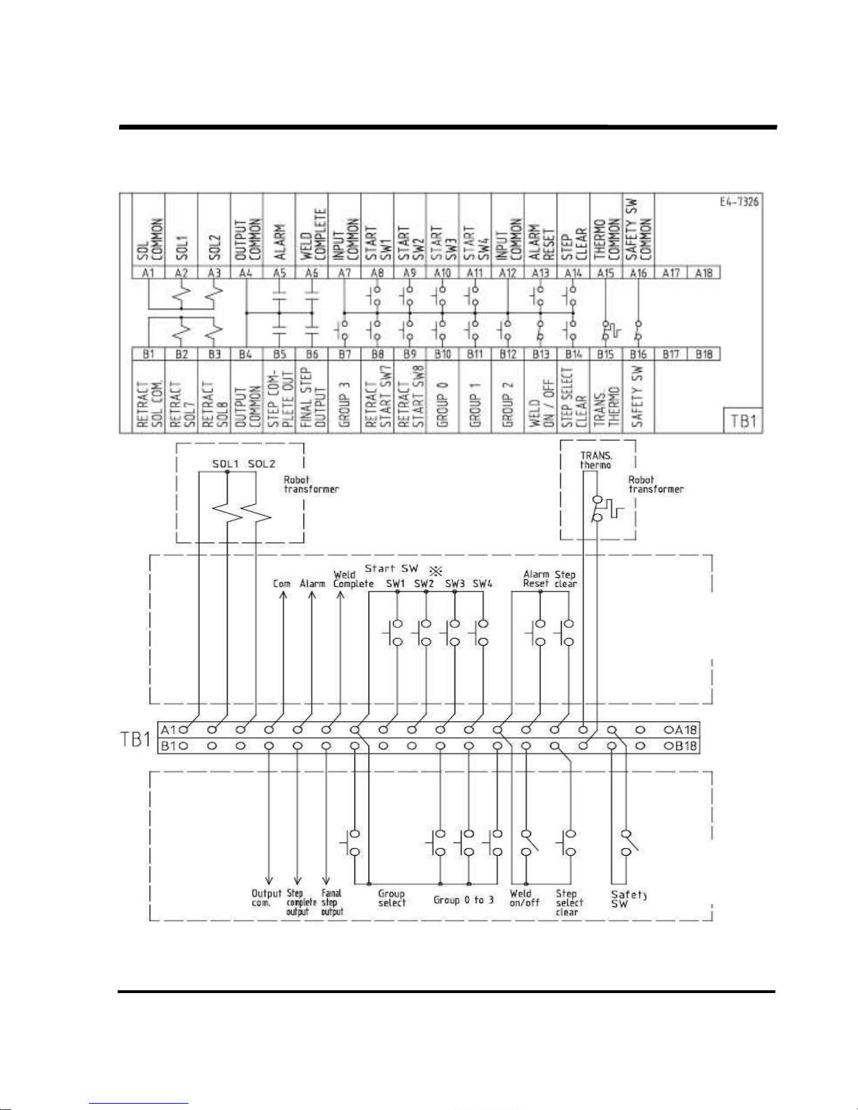
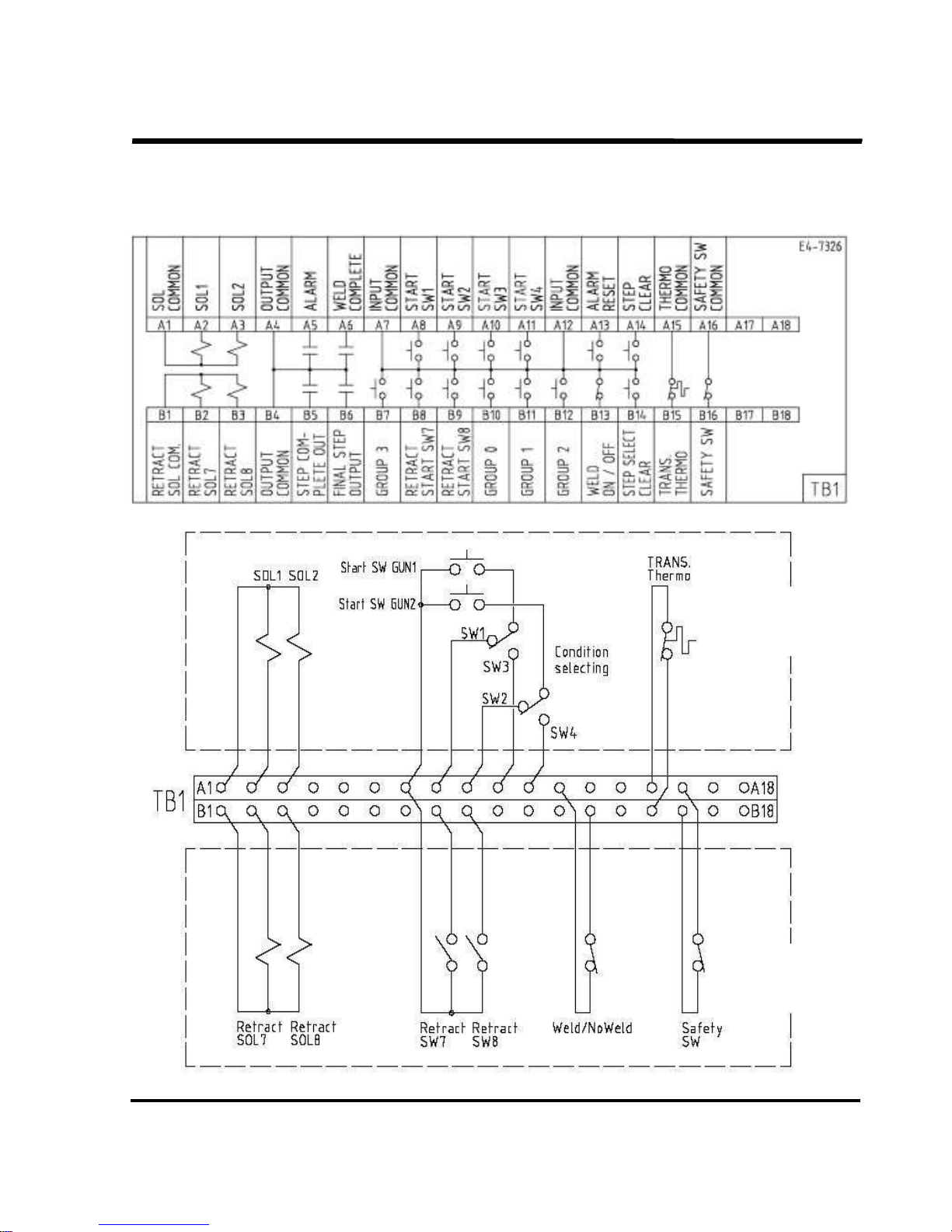
2.5 Connection of the control wires
Connection of the control wiresConnection of the control wires
Connection of the control wires
Connect the terminal block TB1 on the front of the main unit.(See the instruction on the seat.)
Connection item Description
SOL1 and 2 Outputs a signal to each of the solenoid valves of GUN1 and GUN2.
SOL7 and 8
Outputs a signal to the retract valves. Can also be used as outputs
to the GUN3 and GUN4 solenoid valves.
Alarm output
Output an alarm signal on occurrence of fatal or warning(caution)
alarms.
Related parameters:
“Caution”,” TESTW ALM”,”ALM Mode”,”ALM Out”
Step Up Finish Output
Outputs a signal on completion of the specified steps in the Step-
up function.
Last Step output
(Current Detection
signal output)
Outputted upon switching to the last step order. However, this signal
Is turned into the Conduction Detect signal output when the
parameter “CurDetect” is ON.
Output
Output
Output
Output
Hold End
Output of Hold End signal to each spot. When an alarm is found,
Whether this signal is outputted or not depends on the alarm that
has occurred.
Related parameters : “Hold Out”, ”HoldA Dly”
GROUP 0~3
Binary input of Groups 0~3 specifies the welding conditions in
Groups 0~15
START SW 1~4
1. Activation inputs. Can be used to specify up to 240 welding
conditions in conjunction with groups 0~3
(15 conditions * 16groups=240 conditions)
2. When the Step Select Clear signal and an START SW signal are
inputted at the same time, the specified GUN’s step is reset.
Related parameters: “AB Mode”, “SW Mode”, “One Shoot”
RETRACT START SW 7, 8
An input to start the Retract function.
ALARM RESET Short-circuiting this will reset a currently issued alarm.
WELD ON/OFF
A Switch to externally operate/stop the welding.
Since N.C.(weld able at the closed position) is set, shorting between
A12 and B13 is required when it is not in use.
STEP CLEAR Clears the Step-up data of up to GUN8
STEP SELECT CLEAR
Inputting this signal and the Start SW simultaneously will specify a
gun number and clears its Step data. See Section “4.13 Step
resetting” for details.
TRANS. THERMO
This input connects the thermo wire from the welding transformer.
N.C.(normally closed)
Input
Input
Input
Input
SAFETY SW
Switch to stop the timer in an emergency and used for other
purposes. N.C.(operative at the closed position)
SSSSTN
TNTN
TN21 Series
21 Series21 Series
21 Series
OBARA
OBARA OBARA
OBARA KOREA
KOREAKOREA
KOREA
PAGE 20-
Connect Example of Robot control Board
Condition: B Mode (binary switch input) Step control is enable.
※ 1: Refer to Section, 2.7 “Inputting Start Switch and Instructions”.
※ 2: The step last stage signal output works instead of current detection signal output when the
Parameter is effective.
connect these as necessary to
control it on the robot control panel.
Connection to
Portable TRANS.
Terminal box
Connection to
Portable TRANS.
Terminal box
SSSSTN
TNTN
TN21 Series
21 Series21 Series
21 Series
OBARA
OBARA OBARA
OBARA KOREA
KOREAKOREA
KOREA
PAGE 21-
Connection Example of Portable Transformer
Condition: Selectable between A-Mode and 1 retracted gun
Connection to
Portable TRANS.
Terminal box
Connection to
Portable TRANS.
Terminal box
SSSSTN
TNTN
TN21 Series
21 Series21 Series
21 Series
OBARA
OBARA OBARA
OBARA KOREA
KOREAKOREA
KOREA
PAGE 22-
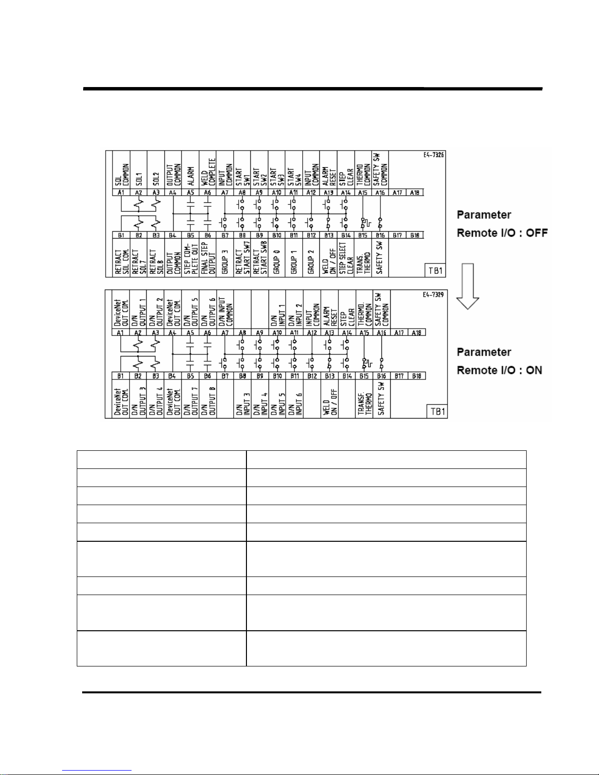
2.6 TB1 Input / Output for Parameter setting
2.6 TB1 Input / Output for Parameter setting 2.6 TB1 Input / Output for Parameter setting
2.6 TB1 Input / Output for Parameter setting ““““Remote I/O: ON
Remote I/O: ONRemote I/O: ON
Remote I/O: ON””””
Each input and Output item became DeviceNet I/O at the time of the
“Remote I/O: ON” choice. Refer to the bottom table for the details.
Table of TB1 item
TB1
TB1TB1
TB1 Stnadard
StnadardStnadard
Stnadard
D/N Output 1 to 4 -COMMON DC24V output
D/N Output 5 to 8 relay contact output
D/N Input 1 to 6 relay contact input
Alarm reset Short-circuiting this will reset a currently issued alarm.
Weld On/Off
A switch to externally operate/stop the welding.
N.C. (Closed in possible for welding)
Step clear Clears the Step-up data of up to GUN8.
Transf. Thermo
Connection of the thermostat wire of the welding transformer.
N.C (Closed in normal state).
Safety SW
A Switch to stop the timer in case of emergency.
N.C. (Activates when closed.)
SSSSTN
TNTN
TN21 Series
21 Series21 Series
21 Series
OBARA
OBARA OBARA
OBARA KOREA
KOREAKOREA
KOREA
PAGE 23-
2.
2.2.
2.7777 Inputting Start Signal and Instructions
Inputting Start Signal and InstructionsInputting Start Signal and Instructions
Inputting Start Signal and Instructions
When connecting the Activation signal, connect the signal to the Activation switches (1 to 4) and
Groups (0 to 3).
Inputting Start Switch Signal
Inputting Start Switch SignalInputting Start Switch Signal
Inputting Start Switch Signal::::
Setting the parameters on the timer allows you to select A MODE (4 series) and B MODE (15 series).
A MODE (1 ~4: 4 series) 1 group
Series 1 Series 2 Series 3 Series 4
START SW 1
START SW 1 START SW 1
START SW 1 O × × ×
START SW 2
START SW 2 START SW 2
START SW 2 × O × ×
START SW 3
START SW 3 START SW 3
START SW 3 × × O ×
START SW 4
START SW 4 START SW 4
START SW 4 × × × O
B MODE (1~F: 15 series) 1 group
1 2 3 4 5 6 7 8 9 A B C D E F
START
START START
START
SW
SWSW
SW
1111
O × O × O × O × O × O × O × O
START
START START
START
SW
SWSW
SW
2
2 2
2
× O O × × O O × × O O × × O O
START
START START
START
SW
SWSW
SW
3
3 3
3
× × × O O O O × × × × O O O O
START
START START
START
SW
SWSW
SW
4
4 4
4
× × × × × × × O O O O O O O O
Group input :
All the series, when put together, are called a group. There are 16 different groups consisting of
Group 0 to Group F. Each group is specified by a binary input. As shown in the table below, no
group input denotes Group 0.
Group selection (0 ~ F: 16 groups)
Group
Group Group
Group
0 1 2 3 4 5 6 7 8 9 A B C D E F
Group 0
Group 0 Group 0
Group 0 × O × O × O × O × O × O × O × O
Group 1
Group 1 Group 1
Group 1 × × O O × × O O × × O O × × O O
Group 2
Group 2 Group 2
Group 2 × × × × O O O O × × × × O O O O
Group 3
Group 3 Group 3
Group 3 × × × × × × × × O O O O O O O O
Maximum number of conditions
Maximum number of conditions Maximum number of conditions
Maximum number of conditions =
= =
= 15
1515
15 series
seriesseries
series X 16
X 16 X 16
X 16 groups
groupsgroups
groups = 240
= 240 = 240
= 240 con
concon
conditions
ditionsditions
ditions
SSSSTN
TNTN
TN21 Series
21 Series21 Series
21 Series
OBARA
OBARA OBARA
OBARA KOREA
KOREAKOREA
KOREA
PAGE 24-
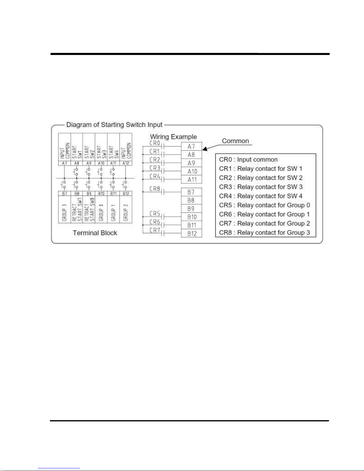
Inputting Instructions of Start Signal
In B-Mode, a long interval between activation of each Start switches may select a wrong Series. Keep the
intervals between activation of each Start switch tithing 5ms. Alternatively, the following method is available.
- Example of Start Switch Input –
At first, close the relays, CR1~8, and then close the contact, CR0, after CR0 short interval.
This method of closing the contact, CR0, after closing the six relays poses no problem if the differences in
closing timing of the relays are moderate.
2.8 Step Clear
2.8 Step Clear2.8 Step Clear
2.8 Step Clear
If the step up function is being used, then inputting a step clear signal to the TB1 terminal block will clear the
gun step conditions.
(Note) When the parameter “Ps” and “P8” are both enable, step series1 only can be cleared by this input
signal (TB1-A14)
2.
2.2.
2.9999 Step
Step Step
Step Select
Select Select
Select Clear
ClearClear
Clear
Inputting a signal to Step select clear and Start switch on the TB1 terminal block at the same time allows a
gun number to be specified and its step data to be reset. And Step select clear follows the data established
in Step return (Welding condition).
How to specify the GUN No.
In A Mode
Gun 1 STEP SELECT CLEAR+INPUT COMMON+START SW1
Gun 2 STEP SELECT CLEAR+INPUT COMMON+START SW2
Gun 3 STEP SELECT CLEAR+INPUT COMMON+START SW3
Gun 4 STEP SELECT CLEAR+INPUT COMMON+START SW4
In B Mode (binary input)
Gun 1 STEP SELECT CLEAR+INPUT COMMON+START SW1
Gun 2 STEP SELECT CLEAR+INPUT COMMON+START SW2
Gun 3 STEP SELECT CLEAR+INPUT COMMON+START SW1+ START SW2
Gun 4 STEP SELECT CLEAR+INPUT COMMON+START SW3

SSSSTN
TNTN
TN21 Series
21 Series21 Series
21 Series
OBARA
OBARA OBARA
OBARA KOREA
KOREAKOREA
KOREA
PAGE 25-
3.
3. 3.
3. INITIAL POWER
INITIAL POWERINITIAL POWER
INITIAL POWER----ON PRECAUTIONS
ON PRECAUTIONSON PRECAUTIONS
ON PRECAUTIONS
3.1
3.1 3.1
3.1 Check items before power
Check items before powerCheck items before power
Check items before power----on
onon
on
Before turning on the power, check the following items to ensure that there are no incorrect
connections.
1. Connection of the power cable
2. Connection to the welding transformer.
3. Connection of the grounding wire.
4. Connection or the control line.
5. Check on the cooling water line and flow rate.
3.2
3.2 3.2
3.2 Check items at power
Check items at powerCheck items at power
Check items at power----on
onon
on
When turning on the power:
1. Wear safety goggles and insulated gloves.
2. Immediately after the power is turned on, check for unusual noise or smoke or peculiar odor.
3. Make sure that there is no alarm indication on the TP-NET. If an alarm is indicated, take
appropriate corrective action against it referring to Section “9. INSPECTION”.
4. After the power is turned on, check for unusual noise or smoke or peculiar odor.
5. Set the welding condition data as well as parameter data referring to Section “4. TP-NET
OPERATION”.
6. Use the START SW to start the equipment and make sure that the welding guns are
pressurized depending on the activation series
3.
3.3.
3.3
3 3
3 Emergency stop
Emergency stopEmergency stop
Emergency stop
Opening the signal circuit of the “Safety S
Safety SSafety S
Safety Switch
witchwitch
witch” on the TB1 terminal block allows you to stop
any valve outputs from the timer and to cut off the welding current in an emergency. The
stopping method depends on the external connections. The personnel responsible for system
configuration should select the emergency stop function according to the situations.
1.
1.1.
1.
BASIC
BASICBASIC
BASIC
2.
2.2.
2.
INSTALLATION
INSTALLATIONINSTALLATION
INSTALLATION
3.
3.3.
3.
POWER
POWERPOWER
POWER
4.
4.4.
4.
TP
TPTP
TP
5.
5.5.
5.
DP
DPDP
DP
6.
6.6.
6.
MAINTENANCE
MAINTENANCEMAINTENANCE
MAINTENANCE
7.
7.7.
7.
TROUBLE
TROUBLETROUBLE
TROUBLE
8.
8.8.
8.
ALARMS
ALARMSALARMS
ALARMS
9.
9.9.
9.
INSPECTION
INSPECTIONINSPECTION
INSPECTION
10.
10.10.
10.
STORAGE
STORAGESTORAGE
STORAGE
11.
11.11.
11.
SPECIAL
SPECIALSPECIAL
SPECIAL

SSSSTN
TNTN
TN21 Series
21 Series21 Series
21 Series
OBARA
OBARA OBARA
OBARA KOREA
KOREAKOREA
KOREA
PAGE 26-
4. TP
4. TP4. TP
4. TP----NET
NETNET
NET OPERATION
OPERATION OPERATION
OPERATION
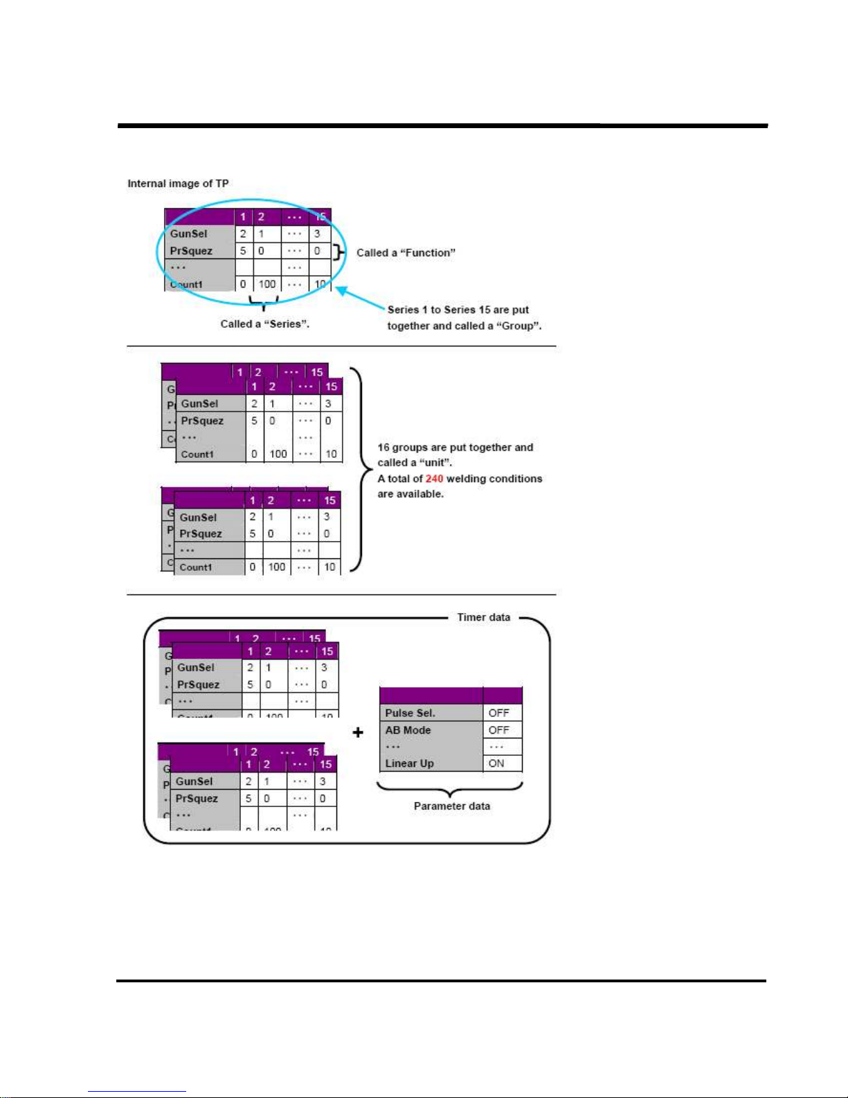
Each timer can have data on 240 welding co
Each timer can have data on 240 welding coEach timer can have data on 240 welding co
Each timer can have data on 240 welding conditions and one set of parameter data.
nditions and one set of parameter data.nditions and one set of parameter data.
nditions and one set of parameter data.
The TP
The TPThe TP
The TP----NET can have data held by five (5) units of this timer.
NET can have data held by five (5) units of this timer.NET can have data held by five (5) units of this timer.
NET can have data held by five (5) units of this timer.
Simply, the TP
Simply, the TPSimply, the TP
Simply, the TP----NET can have as many as 1200 welding conditions.
NET can have as many as 1200 welding conditions.NET can have as many as 1200 welding conditions.
NET can have as many as 1200 welding conditions.
Description of operations from the TP
Description of operations from the TPDescription of operations from the TP
Description of operations from the TP----NET (teaching pendant):
NET (teaching pendant):NET (teaching pendant):
NET (teaching pendant):
Welding result monitor
Check on and change of the parameters
Check on and change of the welding conditions
Check on I/O information (BIT information)
Alarm indication and check on its history
Spot count and reset
Step order count, reset and change
Copy of compare between TM and TP
Copy of the internal data of TP
Description of terms:
Description of terms:Description of terms:
Description of terms:
Welding result monitor・・・・・・ Results of the previous welding.
Welding conditions・・・・・・・・・ The current value, welding time and other condition
can be set as per the customer’s needs
Parameters・・・・・・・・・・・・・・・・ The function can be selected as required by the
customer.
(Repeat, Step up and other functions)
1.
1.1.
1.
BASIC
BASICBASIC
BASIC
2.
2.2.
2.
INSTALLATION
INSTALLATIONINSTALLATION
INSTALLATION
3.
3.3.
3.
POWER
POWERPOWER
POWER
4.
4.4.
4.
TP
TPTP
TP
5.
5.5.
5.
DP
DPDP
DP
6.
6.6.
6.
MAINTENANCE
MAINTENANCEMAINTENANCE
MAINTENANCE
7.
7.7.
7.
TROUBLE
TROUBLETROUBLE
TROUBLE
8.
8.8.
8.
ALARMS
ALARMSALARMS
ALARMS
9.
9.9.
9.
INSPECTION
INSPECTIONINSPECTION
INSPECTION
10.
10.10.
10.
STORAGE
STORAGESTORAGE
STORAGE
11.
11.11.
11.
SPECIAL
SPECIALSPECIAL
SPECIAL
SSSSTN
TNTN
TN21 Series
21 Series21 Series
21 Series
OBARA
OBARA OBARA
OBARA KOREA
KOREAKOREA
KOREA
PAGE 27-
4.1
4.1 4.1
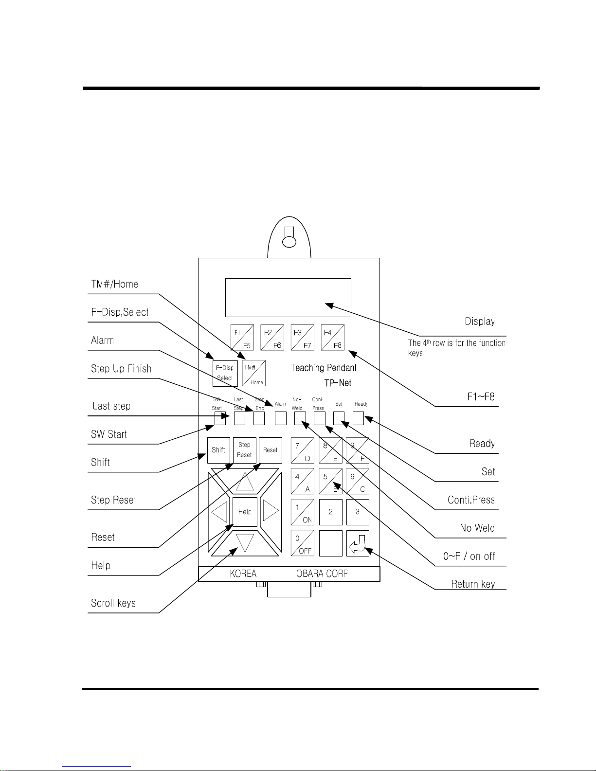
4.1 Names and functions of controls
Names and functions of controlsNames and functions of controls
Names and functions of controls
SSSSTN
TNTN
TN21 Series
21 Series21 Series
21 Series
OBARA
OBARA OBARA
OBARA KOREA
KOREAKOREA
KOREA
PAGE 28-
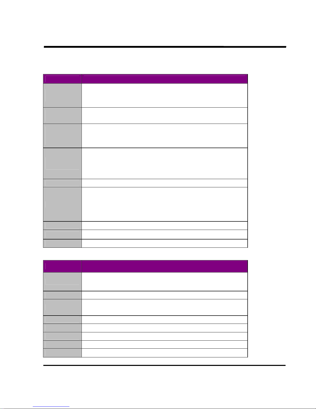
Names of control buttons on the control panel
Names of control buttons on the control panelNames of control buttons on the control panel
Names of control buttons on the control panel
Button name
Button nameButton name
Button name Description of function and operation
Description of function and operationDescription of function and operation
Description of function and operation
F1~F4
F1~F4F1~F4
F1~F4
/F5~F8
/F5~F8/F5~F8
/F5~F8
Selects menu button (function key).
Pressing Shift + a function selects any one of F5 to F8. F8 key is
dedicated to the return function.
FFFF----Disp
DispDisp
Disp
Select
SelectSelect
Select
Determines whether a description should be displayed or cleared on the
bottom line of the display screen.
0~9 & “.”
0~9 & “.”0~9 & “.”
0~9 & “.”
/A~F
/A~F/A~F
/A~F
/ON & OFF
/ON & OFF/ON & OFF
/ON & OFF
Ten-key pad to input data. A to F are selected by pressing Shift +4 to 9.
ON and OFF are selected without pressing Shift. ON = “1” and OFF =
“0”.
TM#
TM#TM#
TM#
/Home
/Home/Home
/Home
- Short-cut button to return to the initial display screen.
- Used for display and edit of the currently connected TM#. Menu
button to select the timer No. to be monitored.
- Pressing Shift + TM#/Home calls up the mode in which the timer No.
to be edited is selected.
Step Reset
Step ResetStep Reset
Step Reset Clears the step value when the step function is enabled.
Reset
ResetReset
Reset
- Resets an alarm that has occurred.
- Clears the gun spot count when the welding spot count is indicated.
(Gun No. is displayed on the top of the screen.)
- Clears the alarm history when it is displayed or suspends other
operations.
↑←→↓
↑←→↓↑←→↓
↑←→↓ Selects scroll direction for the displayed function.
Help
HelpHelp
Help Calls up a help that explains the function letters and details.
Shift
ShiftShift
Shift Auxiliary button to select F5 to F8 and A to F.
Names of indicator lamps
Names of indicator lamps Names of indicator lamps
Names of indicator lamps ((((Status display of the controller
Status display of the controllerStatus display of the controller
Status display of the controller))))
Indicator name
Indicator nameIndicator name
Indicator name
Description of status display
Description of status displayDescription of status display
Description of status display
Ready
ReadyReady
Ready
Illuminates when TP-NET has finished initialization, acquired initial data
via communication and gone into the standby state waiting for data
input.
No Weld
No WeldNo Weld
No Weld Indicates that the timer controller is in No Weld mode.
Conti.Press
Conti.PressConti.Press
Conti.Press
Indicates that the timer controller is in No Weld mode and the
gun-pressure control is in continuous pressurization mode.
Set
SetSet
Set Indicates that the timer controller is in data setting mode.
SW Start
SW StartSW Start
SW Start Indicates that the Start switch in the timer controller is turned on.
Step last stage
Step last stageStep last stage
Step last stage
Indicates that the timer controller has entered the final step.
Step up finish
Step up finishStep up finish
Step up finish Indicates that the timer controller has entered the step end phase.
Alarm
AlarmAlarm
Alarm Indicates that the timer controller has detected trouble.
SSSSTN
TNTN
TN21 Series
21 Series21 Series
21 Series
OBARA
OBARA OBARA
OBARA KOREA
KOREAKOREA
KOREA
PAGE 29-
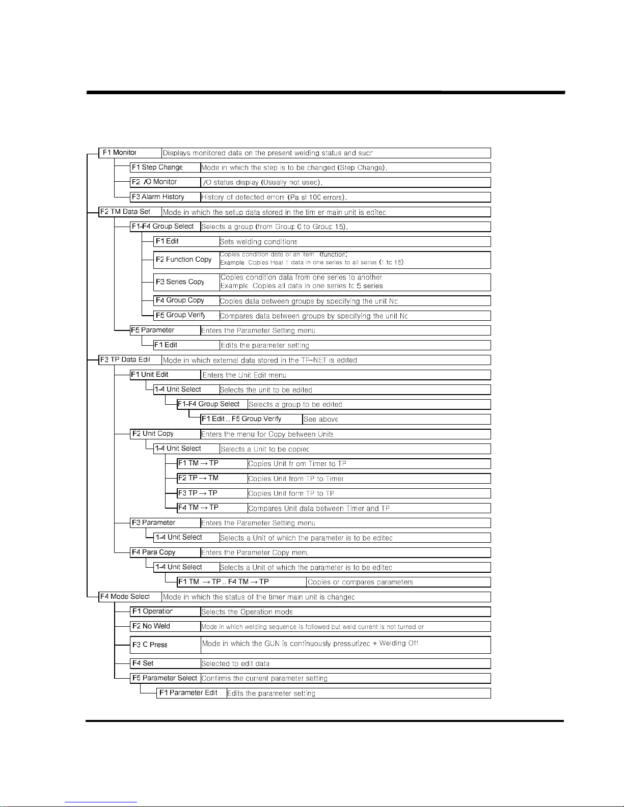
Description of the function key items
Description of the function key itemsDescription of the function key items
Description of the function key items
The screen is selected by pressing any of function keys (F1 to F8) as shown below:
SSSSTN
TNTN
TN21 Series
21 Series21 Series
21 Series
OBARA
OBARA OBARA
OBARA KOREA
KOREAKOREA
KOREA
PAGE 30-
The timer contains data on one unit and parameter data.
TP-NET can contain and hold information on 5 units of the timer.
A total of 1200 welding conditions can be in the TP-NET
 Loading...