

OAV P305 Instruction Manuals
12” PANEL SAW
INSTRUCTION MANUALS

Table of Contents
2
3
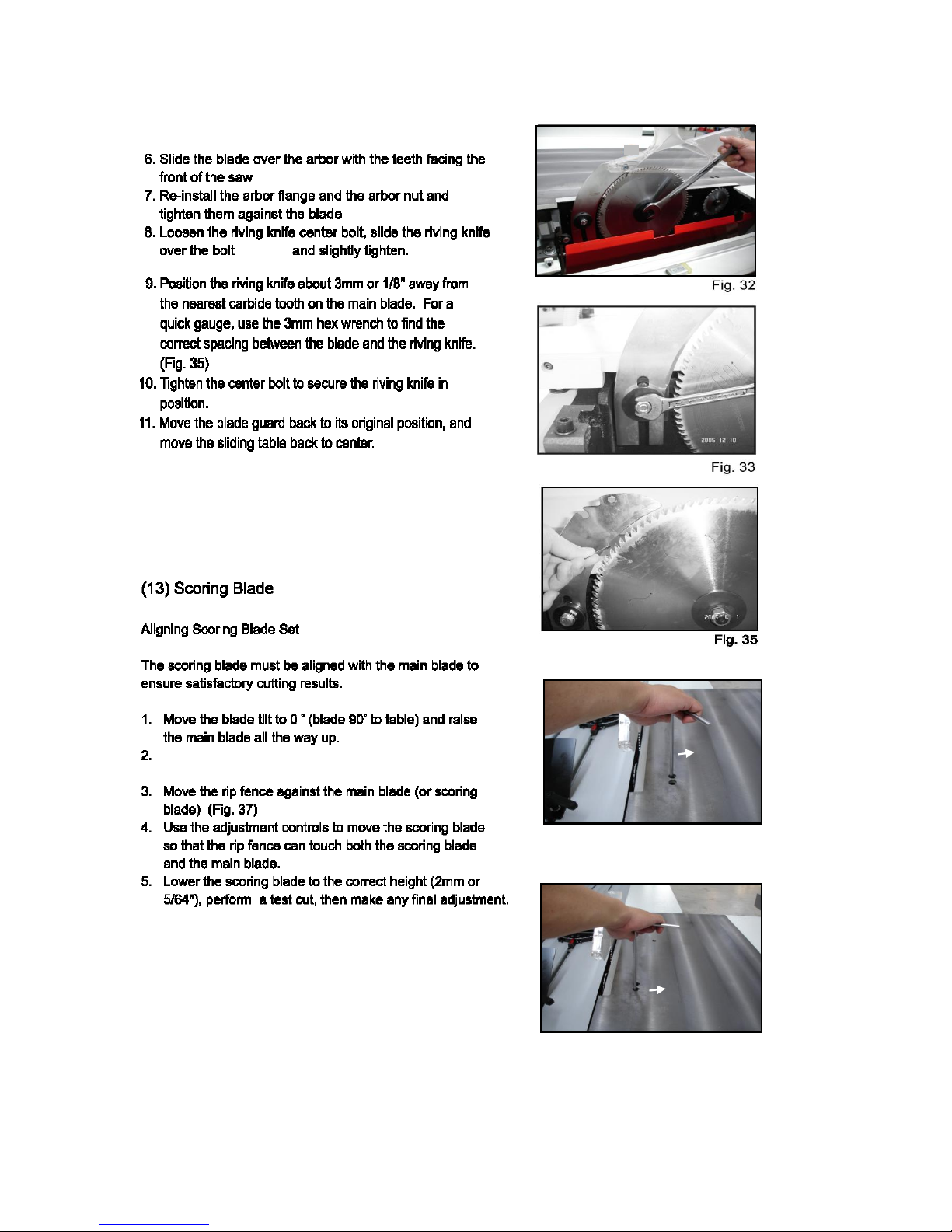
3
4
6
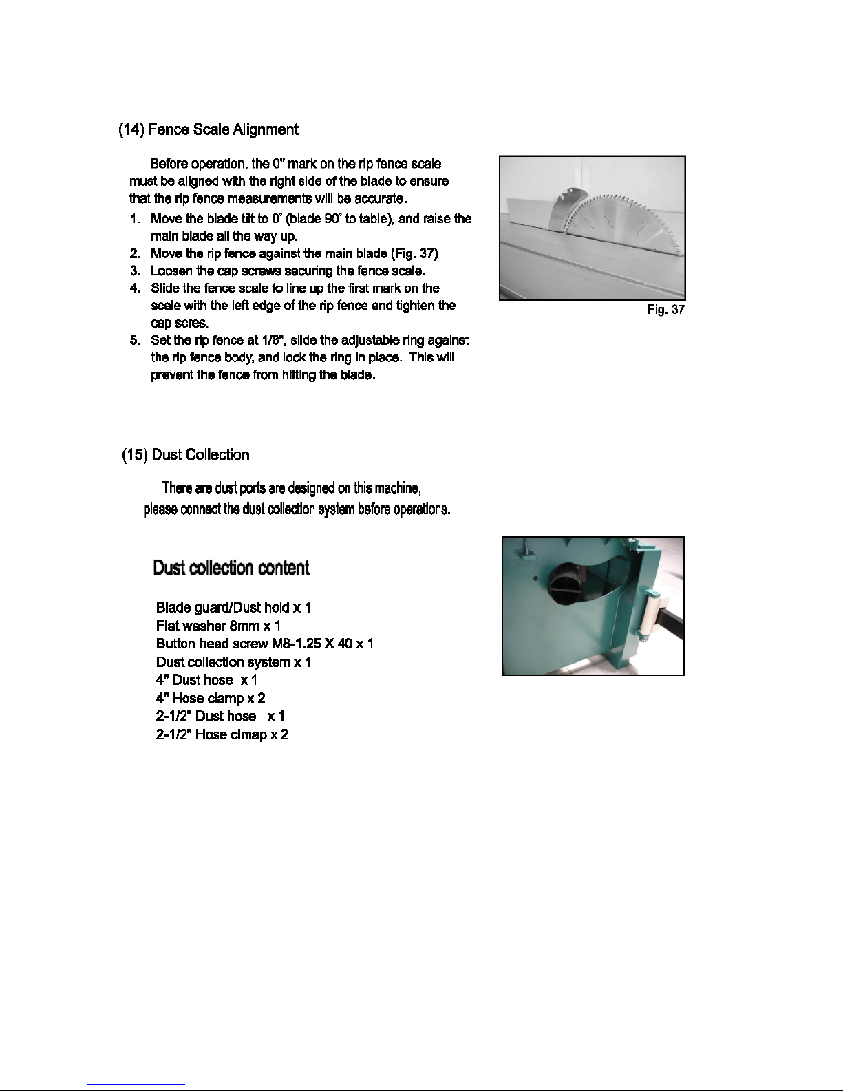
7
7
7
7
8
8
8
8
10
10
11
12
13
14
16
16
17
17
18
18
18
19
19
20
22
24
24
25
25
26
27
27
General Information .......................................................................................................................................
Safety Rules ...................................................................................................................................................
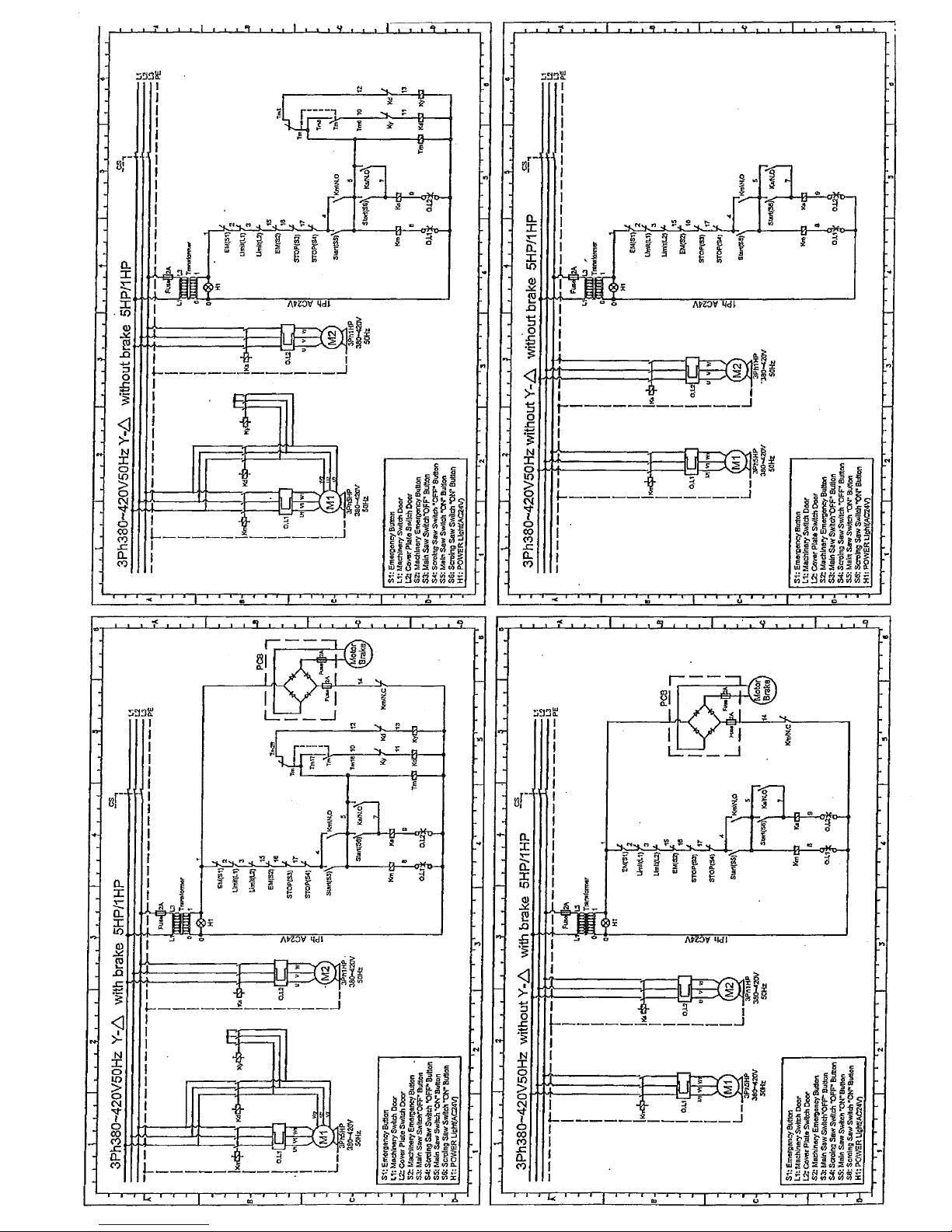
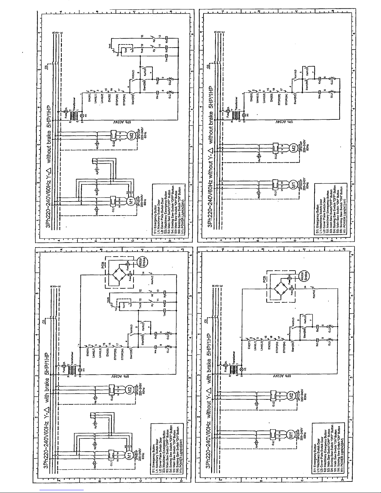
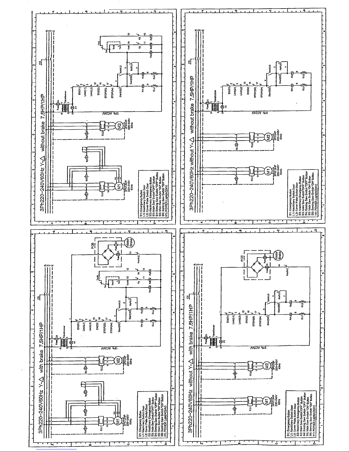
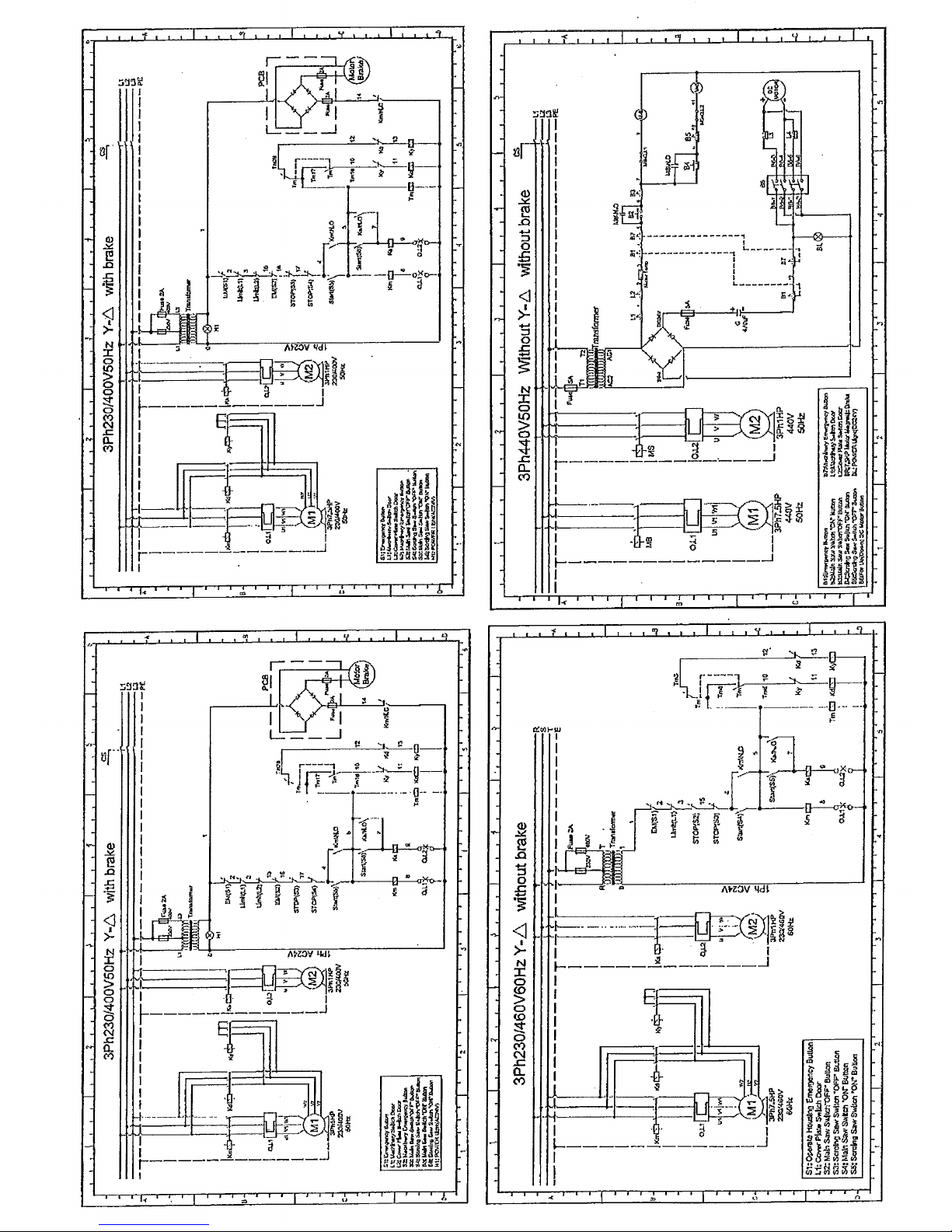
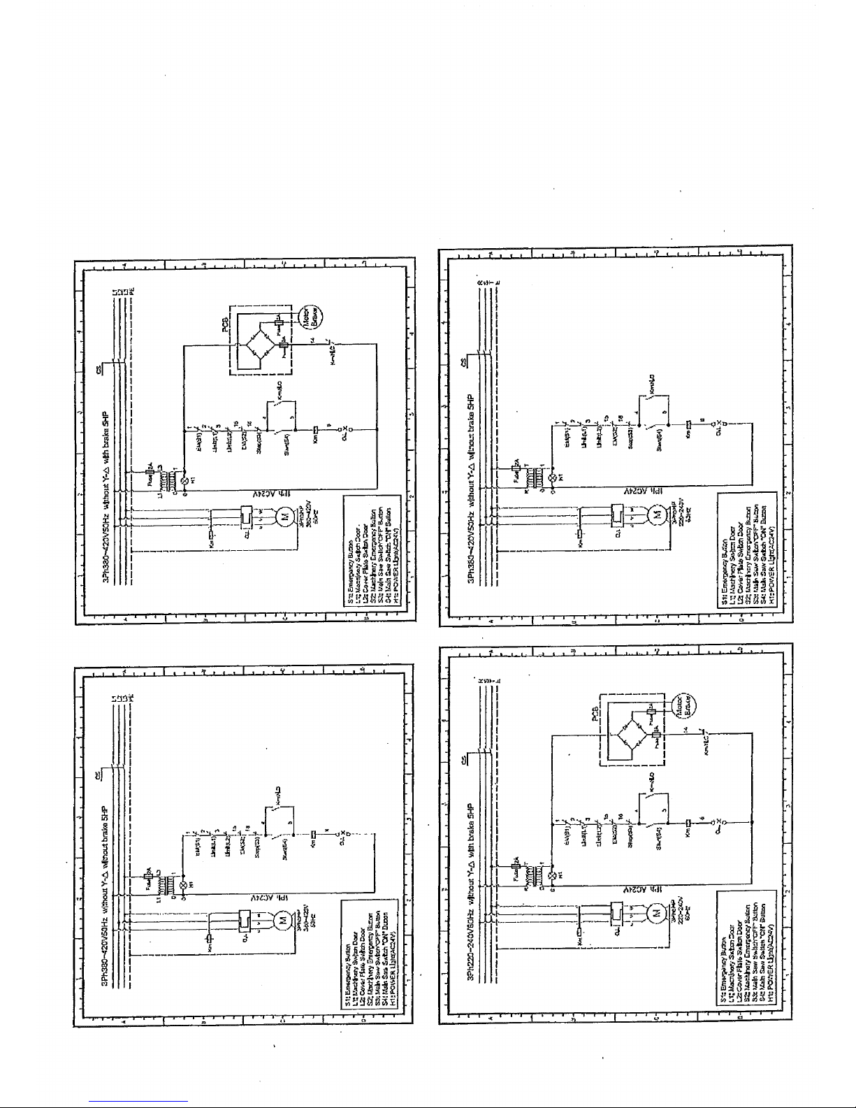
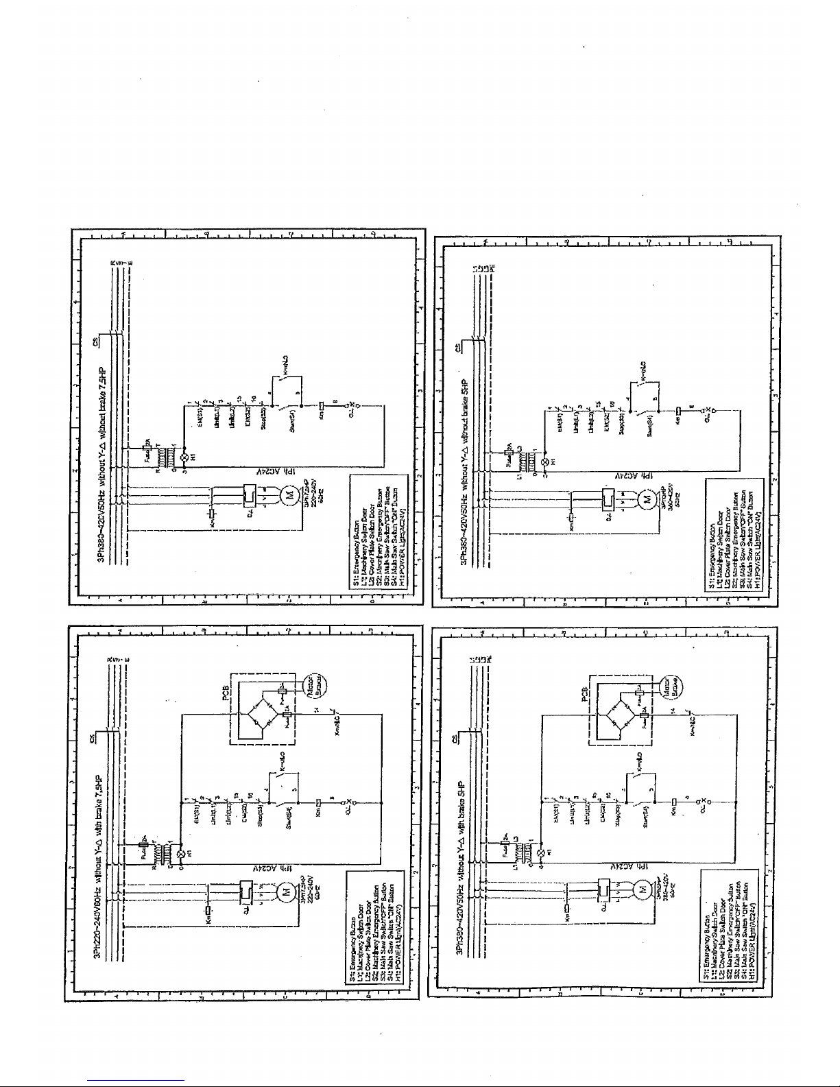
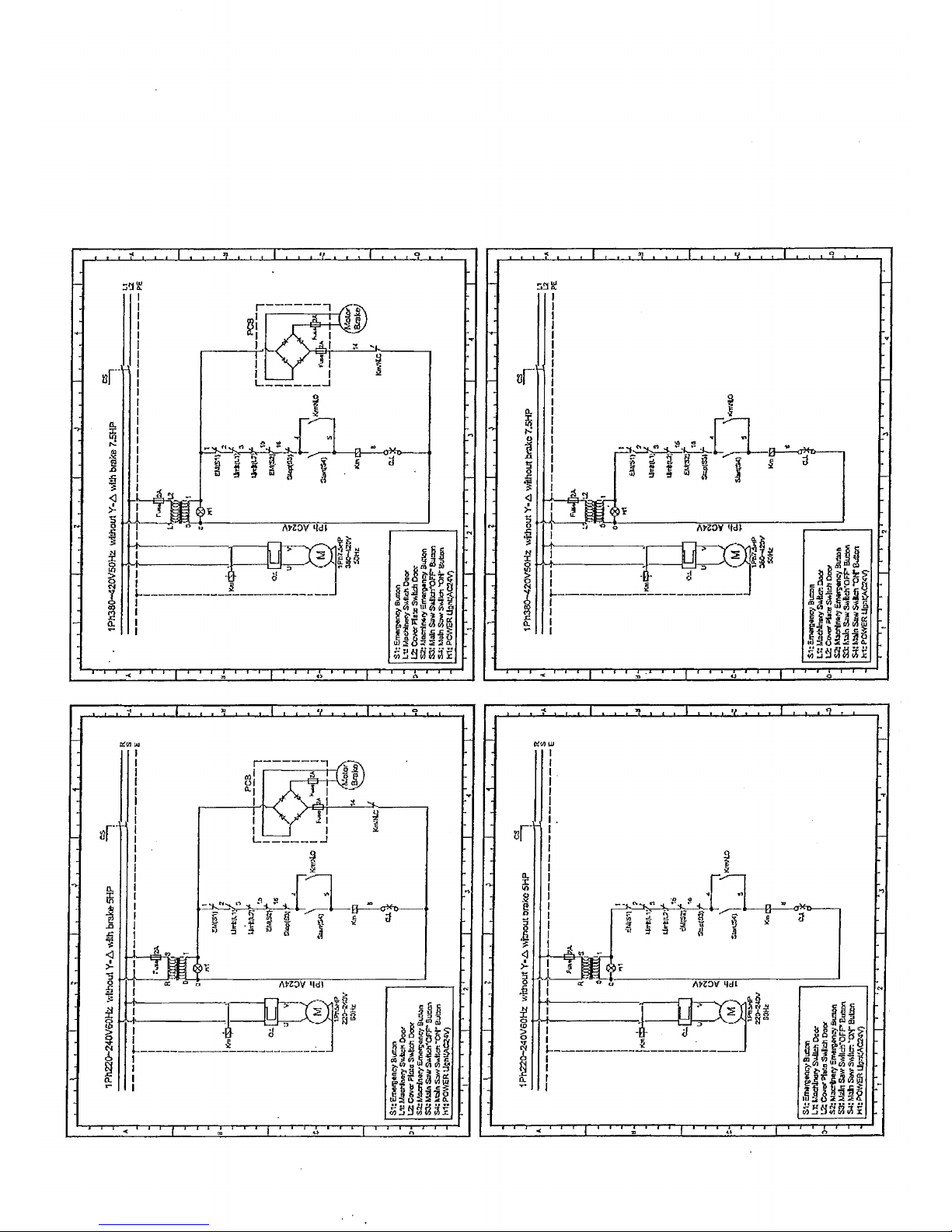
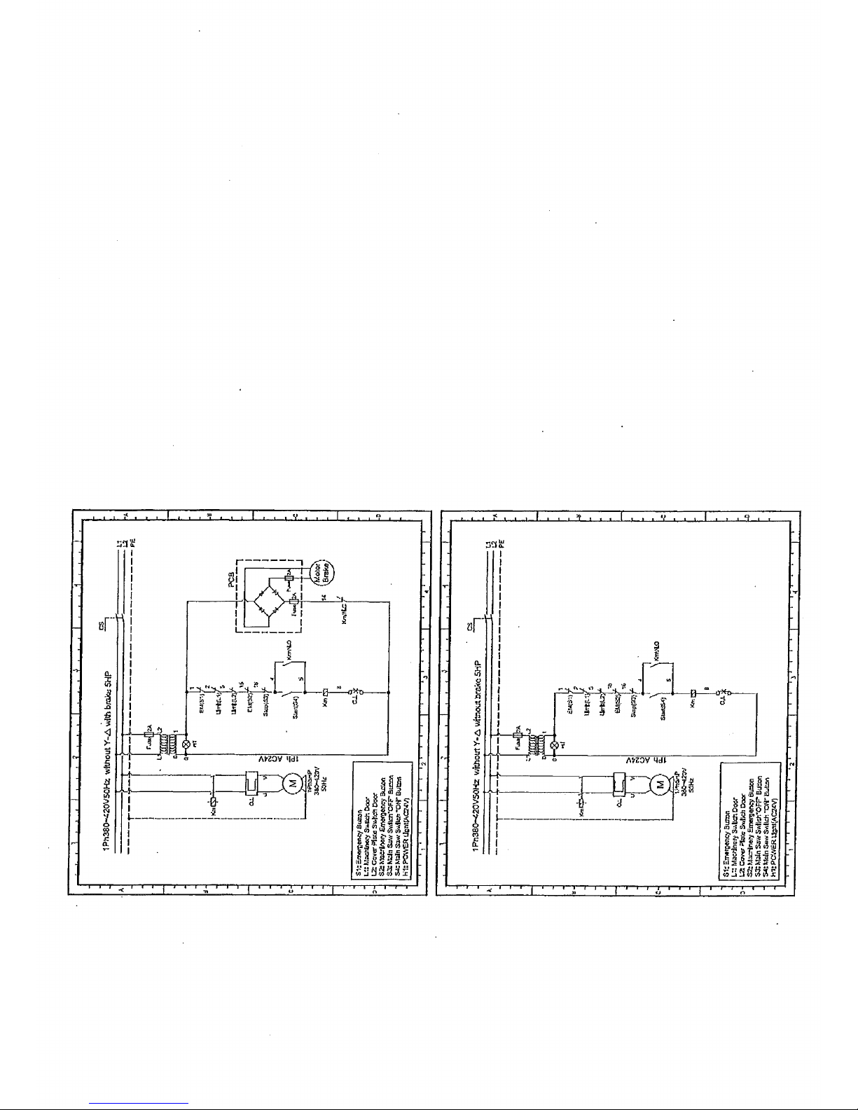
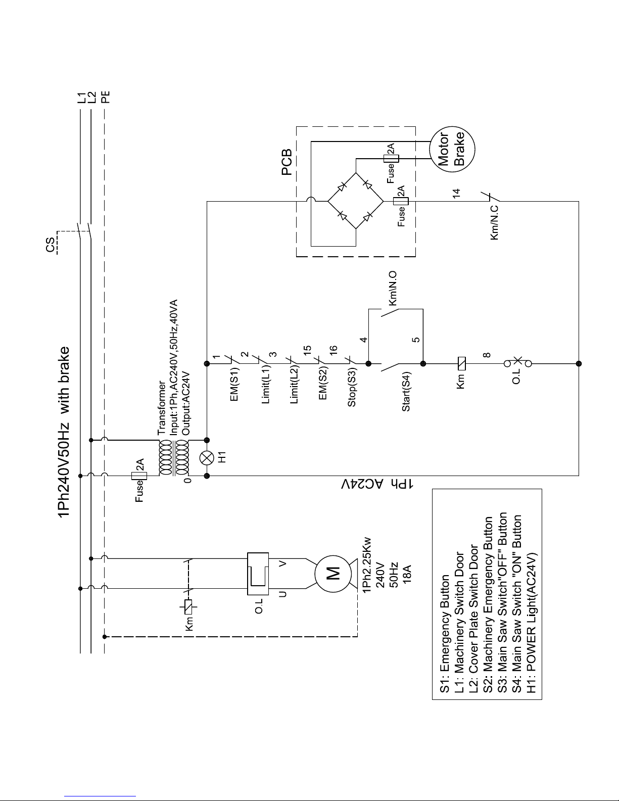
Wiring diagram ...............................................................................................................................................
Specification Sheet ........................................................................................................................................
Main Features ................................................................................................................................................
Assembly And Set Up ....................................................................................................................................
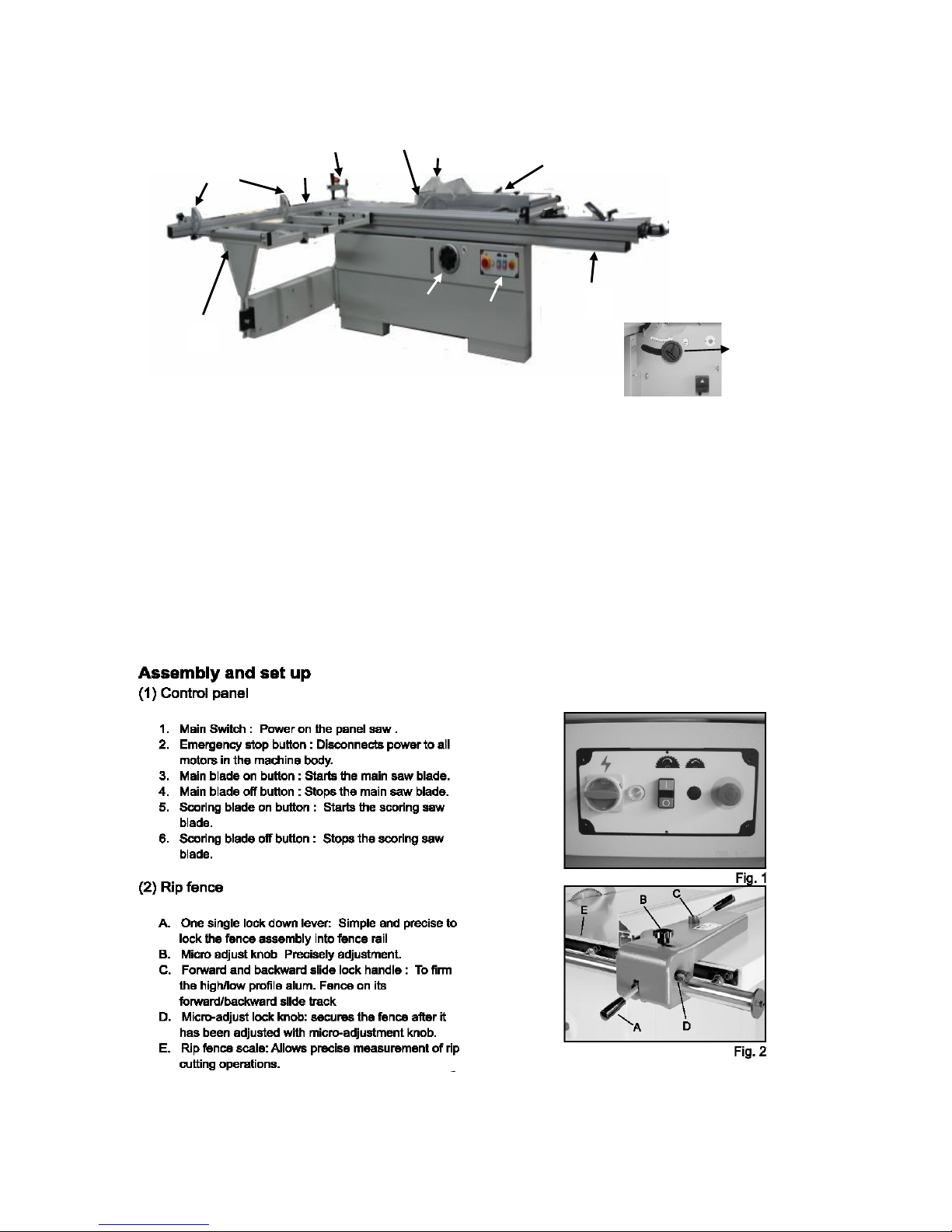
(1). Control Panel ....................................................................................................................................
(2). Rip Fence ........................................................................................................................................
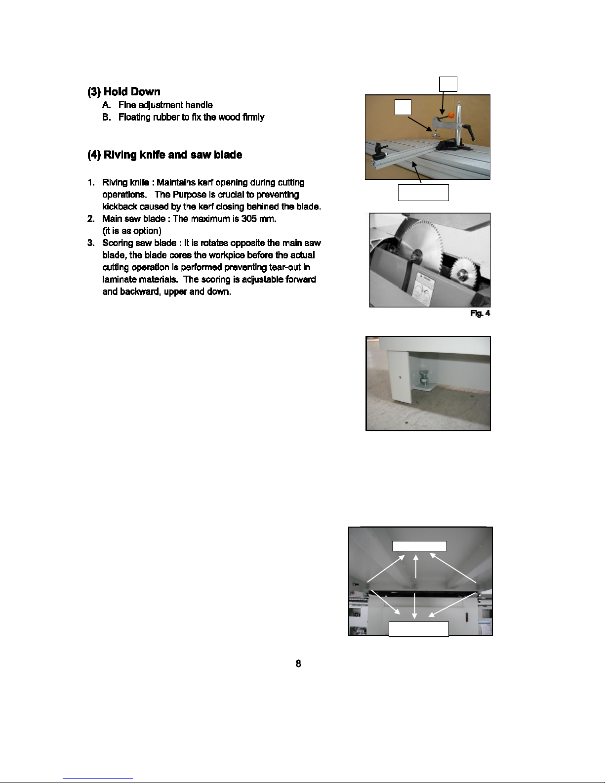
(3). Hold Down .......................................................................................................................................
(4). Riving Knife & Saw Blade ................................................................................................................
(5). Moving & Fixed The Base Unit ........................................................................................................
(6). Extension Table (large & Small) .......................................................................................................
(7). Scale Adjustment ..............................................................................................................................
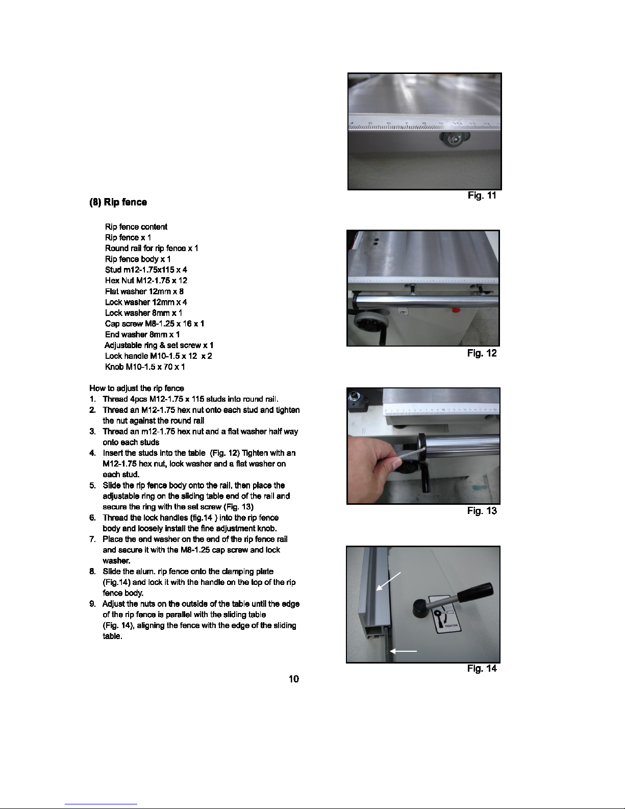
(8). Rip Fence ........................................................................................................................................
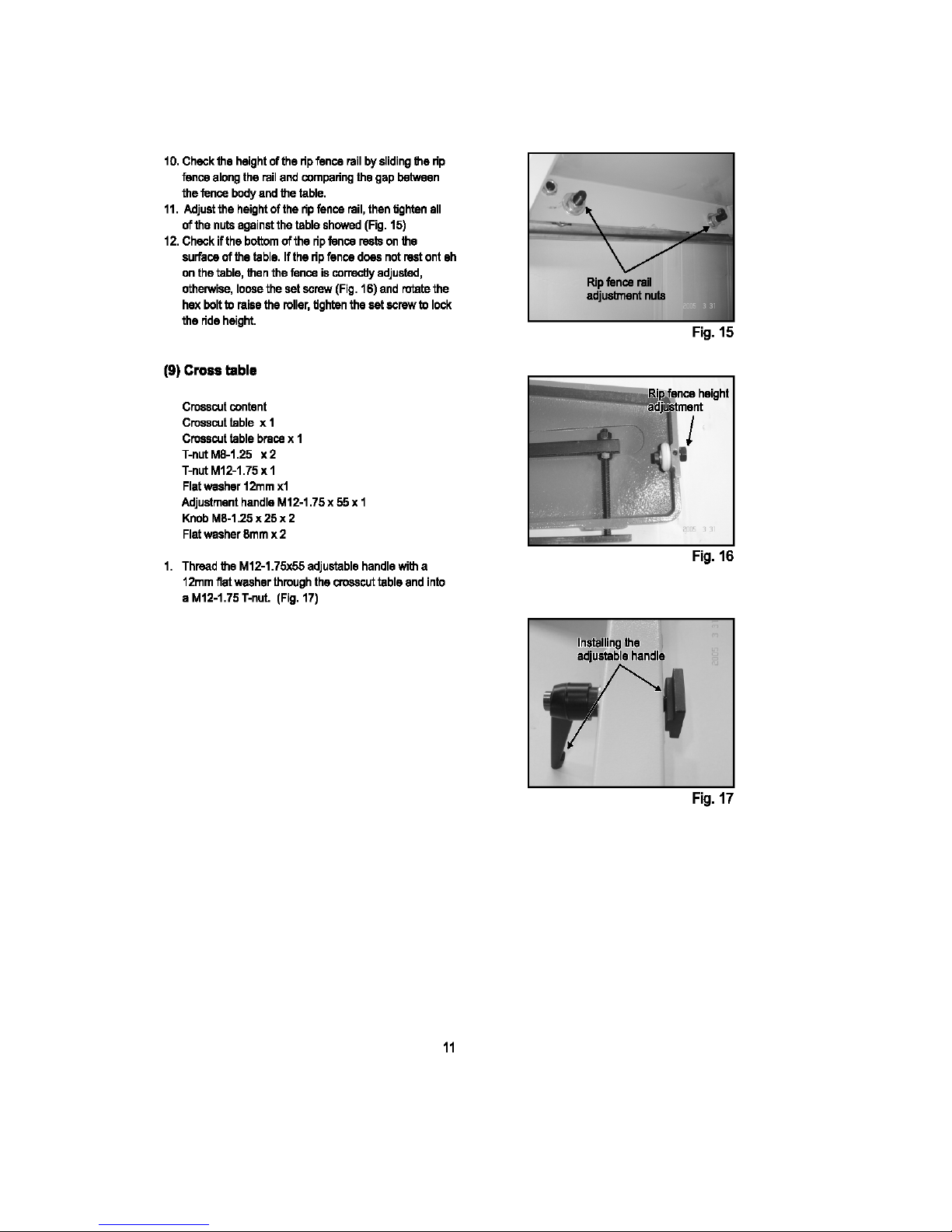
(9). Cross Table ......................................................................................................................................
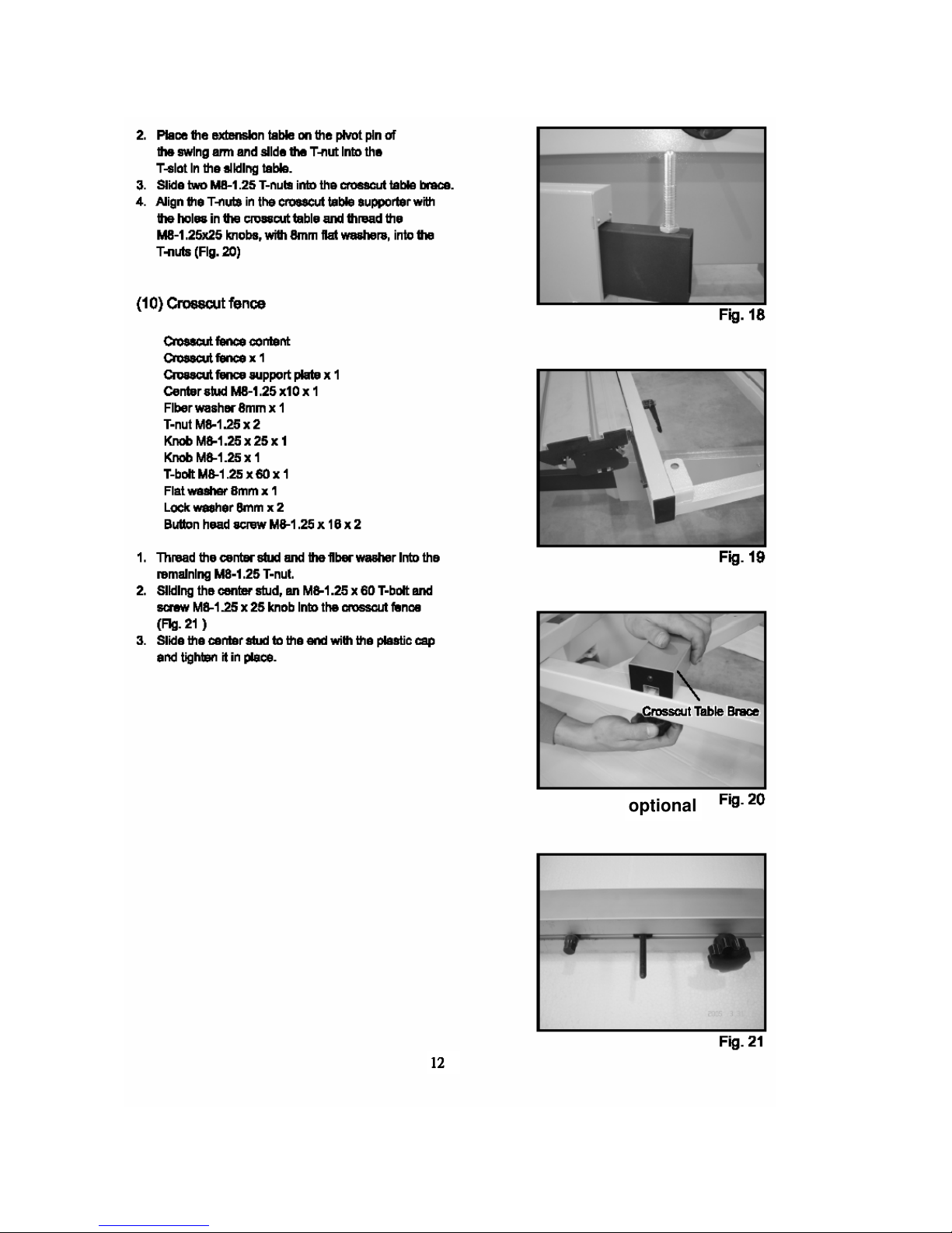
(10). Cross Fence .....................................................................................................................................
(11). Sliding Table .....................................................................................................................................
(12). Main Blade ......................................................................................................................................
(13). Scoring Blade ..................................................................................................................................
(14). Fence Scale Alignment ....................................................................................................................
(15). Dust Collection .................................................................................................................................
(16). Power Cord ......................................................................................................................................
(17). Test Run ...........................................................................................................................................
Operation .......................................................................................................................................................
(1) Change Main Blade ............................................................................................................................
(2) Riving Knife Adjustment ......................................................................................................................
(3) Change Scoring Blade ........................................................................................................................
(4) Rip Cutting ..........................................................................................................................................
(5) Crosscutting ........................................................................................................................................
(6) Miter Cutting .......................................................................................................................................
(7) Lubrication ..........................................................................................................................................
(8) Replace Belts .....................................................................................................................................
(9) Blade Tilt .............................................................................................................................................
(10) Sliding Table Parallel Adjustment ........................................................................................................
(11) Squaring Crosscut Fence To Blade .....................................................................................................
(12) Trouble Shooting .................................................................................................................................

General Information
Safety Rules
OAV
For your own safety read instruction manual before operating
equipment & tools, inc. is specialized to supply full series of panel saw from 1600, 2300, 2500 to 3200mm.
The outlook design of this machine is so unique, complete cast iron trunnion bracket instead of sheet metal,
enlarged outtirgger and carriage, direct dust collection outlet. term its overall condition. The table saw is also an
important products after our band saw series, please enjoy your operation on this machine and If you have any
comment to improve this saw, please don't hesitate to contact us through your agent.
1. To avoid dangerous working environments, do not use stationary machine tools in wet or damp locations, keep
area as clean and well-lit.
2. Wear proper apparel, no loose clothing or jewery which can get caught in moving parts.
3. Never leave when machine is running.
4. Disconnect electrical power before tools are serviced.
5. Remove adjusting keys and wrenches before turning machine on.
6. Be sure that the keys and adjusting wrenches have been removed and all the nuts and bolts are secured.
7. Keep guards in place and in working order.
8. Keep children and visitors away, they should be kept at a safe distance from the work area. Never leave the
machine with power on.
9. Keep hands well away from blades and all moving parts. Do not clear chips and sawdust away with hands.
work
3


Specification Sheet
Model
P305 (one motor)
P305 (two motors)
Cast iron fixed table
dimension
548x896mm
Sliding table dimension
3,200x360mm
Main saw blade
305mm (Max. 355mm)
Main saw bore
30mm
Max. cutting height with
blade at 90°
90mm (25-115mm)
Max. cutting height with
blade at 45°
64mm
Main motor power(3ph)
5HP(3Kw)
Main blade speed
4,000rpm
Scoring saw blade
120mm
Scoring saw blade bore
20mm
Scoring blade motor
power(optional)
3/4HP(0.56Kw)
Scoring blade speed
8,000rpm
Cutting width
1,300mm
Blade tilting adjustment
Manual(0~45°)
Main saw height
adjustment
Manual
Dust collection system
120mm/60mm
N.W./G.W./MEAS.
(Machine)
500/600KGS
2,100*1,100*1,120mm
520/620KGS
2,100*1,100*1,120mm
N.W./G.W./MEAS.
(Sliding table)
80/103KGS
3,300*430*220mm
80/103KGS
3,300*430*220mm
Ctn. Q’ty.
8/19 sets
Due to need of continuous improvement, specifications are subjected to change
without prior notice.
6
Main Feature
1. Flip Stopper-Large stopper for accurate measurements
2. Crosscut Fence-90° and 45° quick position design for a precise crosscutting operation
3. Hold Down : Strong design with fine adjustment and floating rubber pad.
4. Saw Blade Guard : Fully adjustable blade maintains maximum protection around the saw blades.
5. Cast Iron Rip Fence : Micro adjustment for smooth and pricise cutting
6. Sliding table : Double roller carriage with steel bar guidance for smoothly cutting, precise
sliding guides the workpiece through the blade.
7. Control Panel : Simple push button controls for operation
8. Blade Angle Adjusting Handwheel : Manual adjusts the angle of saw blade
9. Blade Height Adjusting Handwheel : Manual adjusts the height of saw blade
10. Cross table : Stronger table and stable to support large size panel during crosscutting operation.
11. Riving Knife : It is prevent kick back caused by the knife closing behind the blade.
1
2
3
4
5
6
7
8
10
11
9
7
(5) Moving & fixing the base unit
Place a level on the saw table and djusting foot stands,
so the saw table is level from left to right and from front to
back. Lock the foot studs in position by tightening their
jam bolts against the machine body. (fig.5)
*Remind firstly to remove the wood ad supporting of motor
before starting the table saw.
A
B
Optional
Fig. 5
Upper lock
Lower adjust
(6) Extension Tables content
How to install the extension tables
1. Thread the set screws into the suitable holes from the
inside of both extension tables.
2. Before the tables are leveleed, please don't completely tighten
the bolts in follw steps.
3. Attach the large extension table with three cap screws, lock
washers and flat washers (Fig. 6)
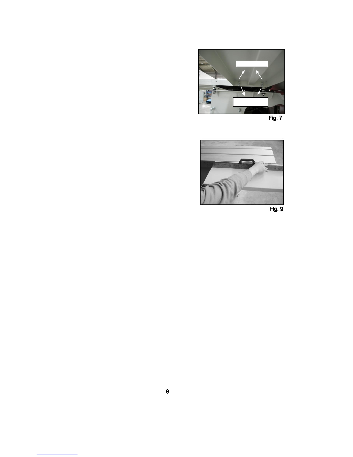
4. Attach the small extension table with cap screws, lock
washer and flat washers(Fig. 7)
5. Check the surfaces 0 degree the table with a
straightedge(Fig. 8)
6. Assemble the supportbracket into the extension table(we
have rest holes for fixing), then adjust the levelling screw of
foot struds in order to make left ext. Table is parallel with saw
table.
Upper lock
Lower adjust
(7) Scale adjustment
1. Tight the cap screws to the extension table and
adjust to be with the top of the table.
Rip fence
Clamping plate
12
1212
12
optional

13

14
fig.30
(fig.31)
15
(fig.32)
(fig.32)
(fig.33)
Adjusting
scoring
rise/fall
Use T tool to adjust scoring blade (Fig. 36-1/-2)
Adjusting
scoring
forwader/back
Fig. 36-1
Fig. 36-2
Adjusting
scoring rise/fall
16
fig.38

17
Run the hose over and aconnect it to the dust
collection system.
Fig.45-1
To fix the scoring by offered U Tool and using the
arbor wrench to remove the nut. (The arbor nut has
right hand threads and loosens by turning
counterclockwise.(fig.45-1)
 Loading...