

Oasis International P8ACSL, PF8ACSL, PF8ACSLEE, PV8ACSL, PVF8ACSL Installation Instructions Manual
...
®
VERSAFILLER®
Model PWEBF (retro fit) and
P*EBF Family of Drinking
Fountains/VersaFiller combo
Installation Instructions
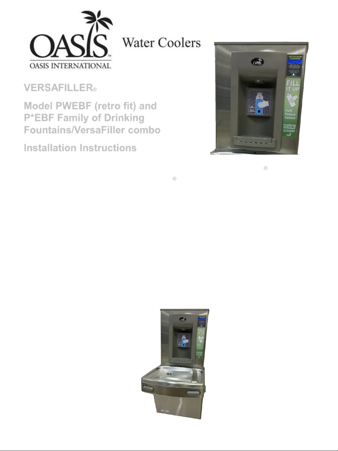
The Hands-Free VersaFiller is an extension of the Aqua Pointe® product line
that mounts directly above Versacooler
does not have two useable plugs, an outlet splitter will need to be used.
If installed onto a refrigerated cooler, chilled water can be dispensed through
the VersaFiller. Otherwise, room temperature water will be dispensed.
The VersaFiller is shipped partially assembled.
® I and II products. If the cooler outlet
On the combo units, the cooler is plumbed and ready to attach to the
VersaFiller.
When completed, the finished assembly will look like this:
1
Section 1: Getting Started
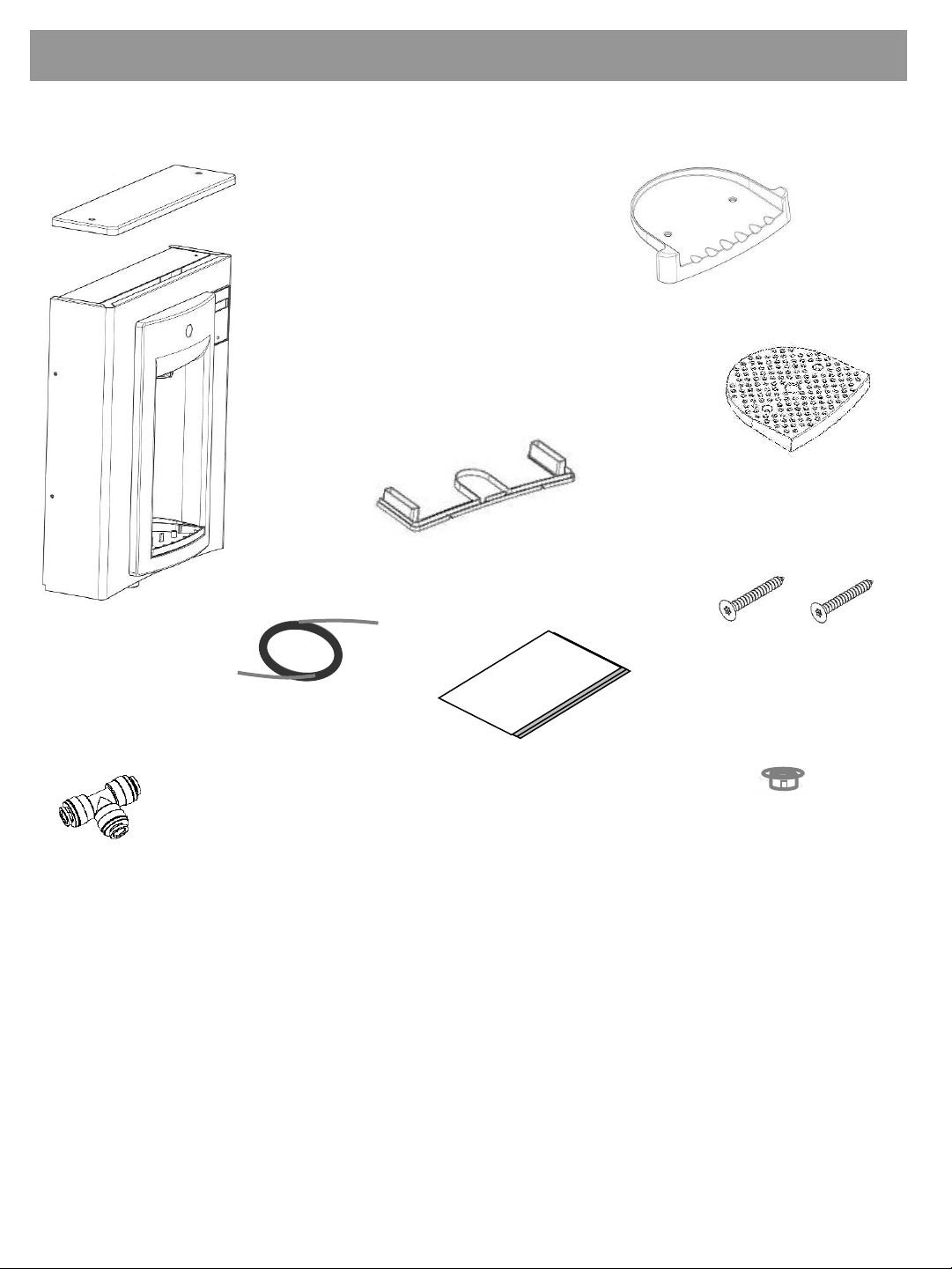
What’s Included:
(Top cap)
VersaFiller Hands-Free
Sports Bottle Filler(with wrapper, alcove
and top cap installed
onto the frame)
Drip tray
Gasket
Anti splash grate
Quick connect
tee fitting
required on split
level units)
(only
3/8” pilot drill and either a step drill bit up to 7/8” diameter that
Electric drill; wrench for punch die
Small tubing cutter for copper tube
1/4“ nut driver
Anti Splash
grate screws (2)
38” of ¼ OD plastic
tubing with 19” of
sponge tubing
insulation
with “Versafiller ready”
coolers)
(included
Installation
instructions
Snap bushing
Tools required:
will drill through SS top or 7/8” diameter punch die (retrofit
version only)
# 2 Phillips screw driver
#15 torx bit driver
2
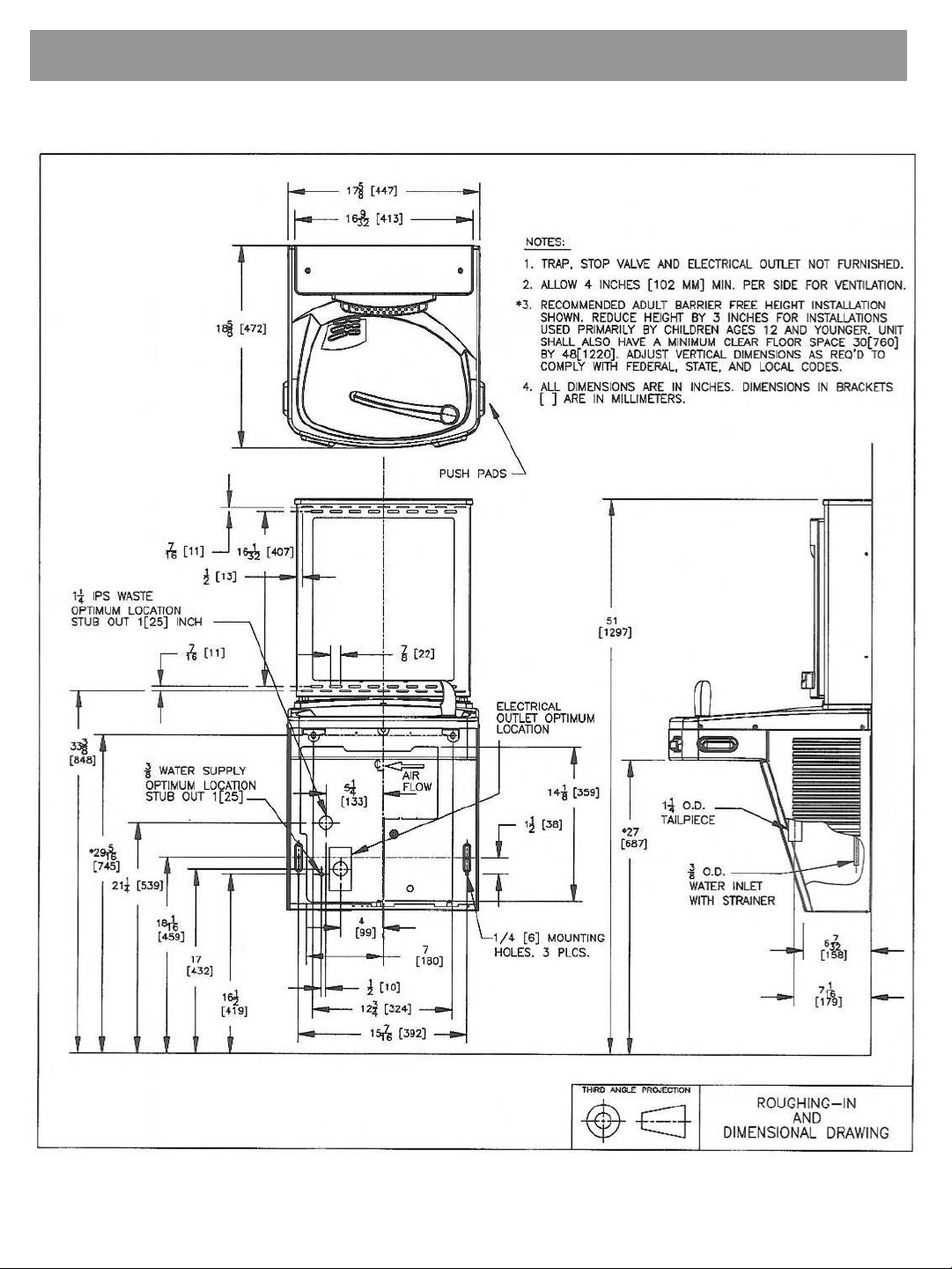
Section 2: Rough In Drawing
Oasis PWEBF: Versacooler® II Models PAC, P8AC with Hands-Free VersaFiller
3
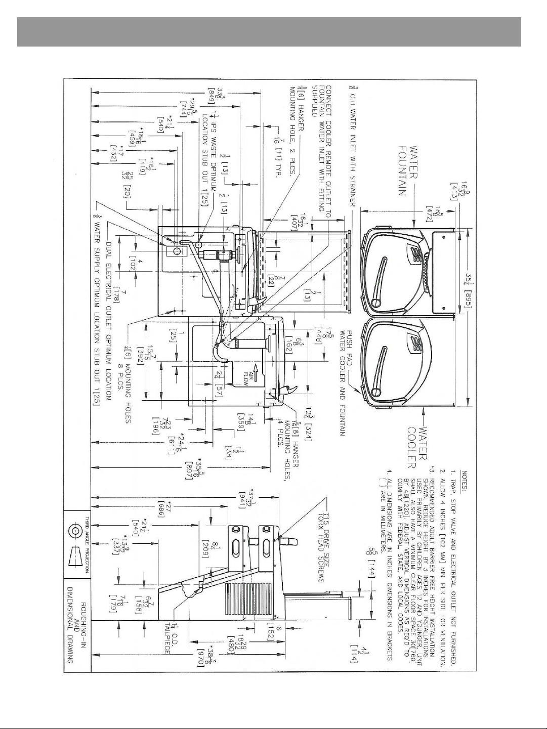
Section 2: Rough In Drawing
Oasis PWEBF: Versacooler® II Split Level Models with Hands-Free VersaFiller
* On split level models, the VersaFiller must be mounted
on the low unit in order to meet ADA guidelines.
4
Section 3: Installation
Note: Proceed to Sect 3B Step 5 if the cooler is
purchased “VersaFiller ready”.
A: Drilling hole in the top for water line connection.
1. Disconnect power by UNPLUGGING unit. It might be necessary to
remove the front panel to get access to the power.
2. Turn OFF water supply to the unit. It might be necessary to remove the
front panel to access the water stop valve.
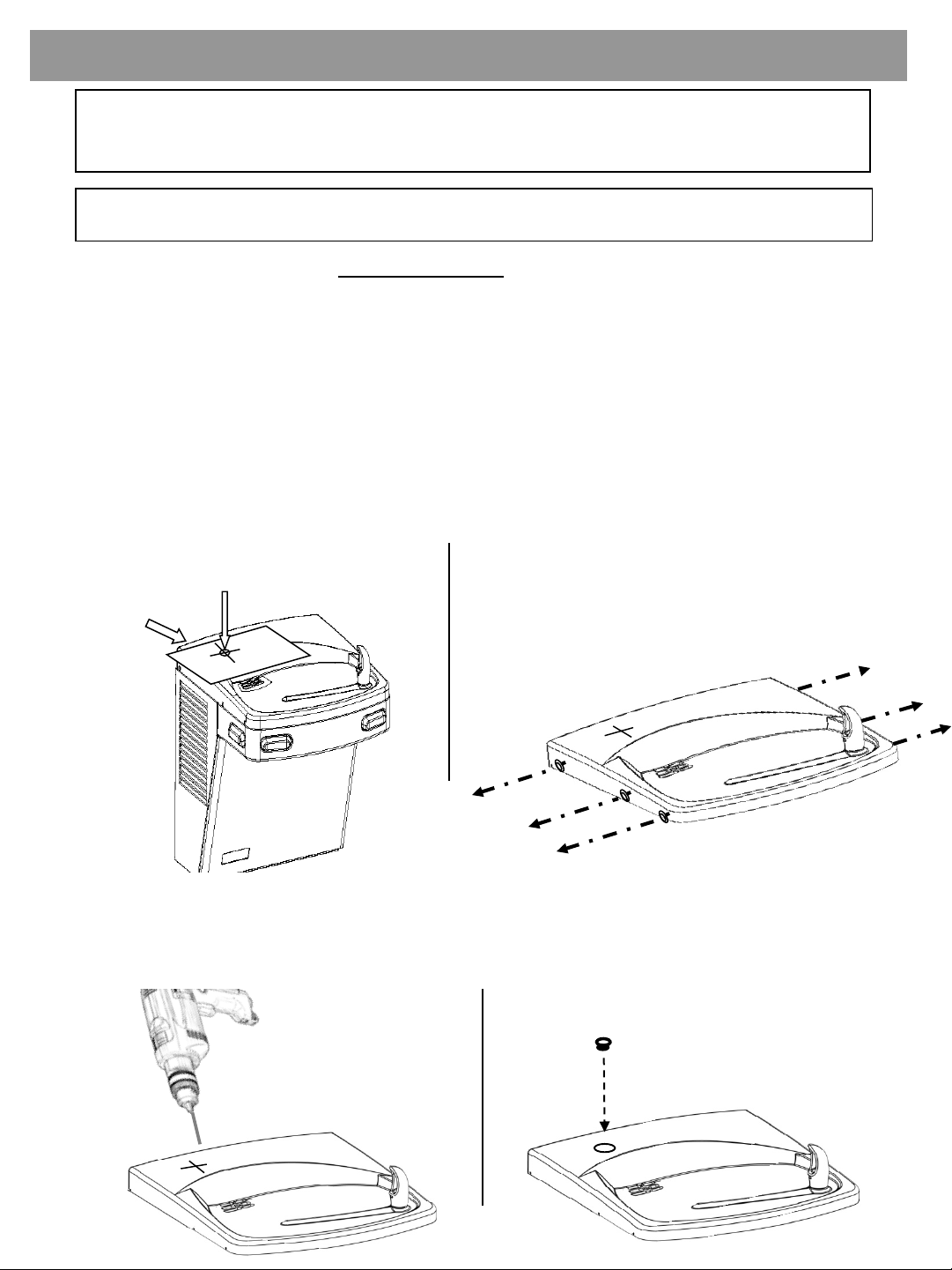
3. Place hole template onto cooler top so it is aligned with the left side of
unit and wall. SEE NEXT PAGE FOR TEMPLATE
4. Mark hole location
5. Remove top from unit.
Mark hole location.
Template
6. Using a step drill bit or 7/8” punch die, make a 7/8” hole through top. You
may want to drill a pilot hole to get these started.
7. Install snap bushing into hole to protect tubing from being cut.
Drill
Remove top from cooler by
removing six #15 torx head screws
on sides of top.
Install bushing
5
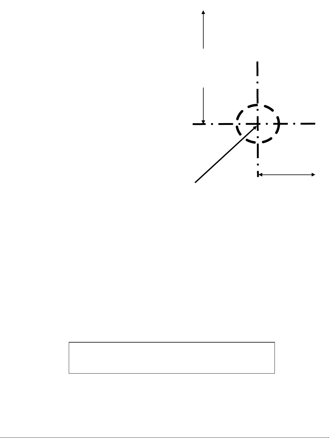
ALIGN THIS EDGE WITH LEFT EDGE OF COOLER TOP
Mark this center point on the
top. Remove the top from the
cooler. Then create a 7/8”
diameter hole through the top
3-1/4”
from
side
PLACE THIS EDGE AGAINST WALL
2-1/8”
from
back
at the marked center point
(step drill bit or punch die).
USE THIS TEMPLATE TO MARK THE
HOLE LOCATION ON COOLER TOP
6

Section 3: Installation
B: Connecting the water line
Note: If you are retrofitting the Versafiller to an existing cooler,
follow the instructions starting on the next page.
For the single “Versafiller ready” cooler, the tube to connect to the Versafiller
is found inside the access panel (the compressor compartment). This tube
supplies cold water from the cooling tank to the Versafiller.
¼” OD tube to connect
to Versafiller
For split level “Versafiller ready” coolers, the tube to plumb in the
Versafiller is packaged in the dummy unit.
Remove tube from bag.
First, remove plug from
fitting on tank drain
Next, insert end of
tube into fitting.
7
 Loading...