


User Manual
C2D900+
Smallest pBTX Desktop
C2D900+ is a high quality, highly scalable basis for your computing
needs. You will find that the C2D900+ System has the following
advantages
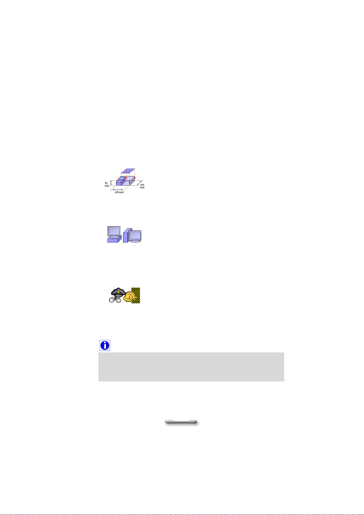
Ultimate small and quiet
C2D900+ is designed in the size that just enough for
pBTX motherboard and LFX power supply unit; no
space wasted inside the chassis. Proprietary thermal
solution delivers best acoustic performance of 26dB
handling office works.
Perfect on office desktops
With the carefully placed vent location, C2D900+ is
able to be placed both vertically and horizontally on
office desktops. It gives user the flexibility to arr ange
desktop space as desired. C2D900+ is also
designed to hold legacy, heavy CRT monitors that
are still commonly using today.
Solid Security and Easy Maintenance
C2D900+ is built with Kensington lock, pad lock, and
Chassis intrusion that secure hardware. Latest Intel
technology provides secure networking and
administrating. Tool-less chassis allows easy
maintenance with level 7 components assembling.
Note:
In order to install C2D900+ System efficiently, Please read this user’s
manual carefully before unpacking and setting up your computer
.
2

Copyright
Copyright © SAMSYNC Corporation 2005. All right reserved.
Disclaimer: SAMSYNC Corporation shall not be liable for technical or editorial errors or
omissions contained herein; nor for incidental or consequential damages resulting from
furnishing this material, or the performance or use this product.
SAMSYNC Corporation reserves the right to change product specification without
notice. Information in this document may change without notice.
No part of this document may be copied, reproduced, or transmitted by any means, for
any purpose without prior written permission from SAMSYNC Corporation.
Safety Instructions
♦ The computer has been tested for conformance to international safety regulations.
Like any electronic device, however, the computer should be used with care. To
protect yourself from possible injury and to minimize the risk of damage to the
computer, read and follow all the safety instructions mentioned in this manual.
♦ A modem card will be bundled with the system and installed in the extension slot. Do
not touch the modem card if you are using the system. This may cause an electrical
shock.
WARNING: Do not attempt to service the computer yourself. Opening or removing
covers might expose you to dangerous voltage points or other risk, have a qualified
person repair it.
WARNING: Keep hair, loose clothing, fingers, and all parts of body away from openings,
moving parts and fan.
WARNING: Do not operate the computer with the cover removed.
WARNING: Always disconnect all telephone lines & all power cords from the wall outlet
before servicing or disassembling this product. To reduce the risk of personal injury from
electrical shock or hot surfaces, disconnect the power cord from the wall outlet, and allow
the internal system components to cool before touching.
3

WARNING: This equipment is designed for connection to a grounded (earthed) outlet.
The grounded type plug is an important safety feature. To reduce the risk of electrical
shock, damage to your equipment, or loss of data, do not disable this feature.
General Guidelines
♦ Read all of these instructions.
♦ Save these instructions for future use.
♦ Follow all warnings and instructions marked in the computer.
♦ Except as explained elsewhere in this manual, do not attempt to service the
computer yourself. Opening or removing covers that are marked “Do Not Remove”
might expose you to dangerous voltage points or other risks. Refer all servicing of
marked components to a qualified personnel.
Installation Restrictions
1. Follow all warnings and instructions marked on the product.
2. Unplug this product from the wall outlet before cleaning. Do not use liquid cleaners
or aerosol cleaners. Use a damp cloth for cleaning. Ensure that no liquid enters the
system.
3. Do not use this product near water. For example, near a bathtub, washbowl, kitchen
sink or laundry tub, in a wet basement or near a swimming pool.
4. Do not connect or disconnect cables during a thunderstorm.
5. Do not place this product on an unstable cart, stand, or table. The product may fall,
causing serious damage to it.
6. Avoid using a telephone (other than a cordless type) during an electrical storm.
There may be remote risk of electric shock from lightning.
7. Do not use the telephone to report a gas leak in the vicinity of the leak.
8. Slots and openings in the cabinet and the back or bottom are provided for ventilation;
to ensure reliable operation of the product and to protect it from overheating, these
openings must not be blocked or covered. The product should never be placed near
or over a radiator or heat register, or in a built-in installation unless proper ventilation
is provided.
9. This product should be operated from the type of power indicated on the marking
label. If you are not sure of the type of power available, consult your dealer or local
power company.
10. Do not allow anything to rest on the power cord. Do not locate this product where
persons will tread on the cord.
11. If an extension cord is used with this product, make sure that the total ampere rating
of the equipment plugged into the extension cord does not exceed the extension cord
ampere rating. Also, make sure that the total rating of all products plugged into the
wall outlet does not exceed the fuse rating.
12. Never push objects of any kind into this product through cabinet slots as they may
touch dangerous voltage points or short out parts that could resulting a fire or
electronic shocks. Never spill liquid of any kind on the product.
4

13. To reduce the risk of fire, use at least No. 26 AWG wire for the telecommunication
line cord.
14. Always disconnect all telephone lines & all power cords from the wall outlet before
servicing or disassembling this product. And, refer it for servicing to qualified service
personal under the following conditions:
a. When the power cord or plug is damaged or frayed.
b. If liquid has been spilled into the product.
c. If the product has been exposed to rain or water.
d. If the product does not operate normally when the operating instructions are
followed. Adjust only those controls that are covered by the operating instructions,
since improper adjustment of other controls may result in damage and will often
require extensive work by a qualified technician to restore the product to normal
condition.
e. If the product has been dropped or cabinet has been damaged.
f. If the product exhibits a distinct change in performance, indicating a need for
service.
5
Electrical Restrictions
WARNING: This equipment is designed for connection to a grounded (earthed) outlet. The
grounding type plug is an important safety feature. To reduce the risk of electrical
shock, damage to your equipment, or loss of data, do not disable this feature.
Power Cord Set Requirements
The power cord set (appliance coupler, flexible cord, and wall plug) you received with
the computer meets the requirements for use in the country where you purchased the
equipment.
Power cord sets for use in other counties must meet the requirements of the country
where you use the computer. For more information on power cord set requirement,
contact your local authorized dealer, reseller, or service provider.
Laser Compliance Statement
The CD-ROM / DVD-ROM / CD-RW / DVD-RW drive in this computer is a laser
product. The CD-ROM / DVD-ROM / CD-RW / DVD-RW drive’s classification label
(shown below) is location on the drive.
Class 1 laser product
Caution: Invisible laser radiation when open. Do not stare into beam.
Caution: Use to any controls or adjustments or procedures other than
those specified herein may result in hazardous radiate exposure. To
prevent exposure to laser emanations (Harmful to Human eyes), Do not
attempt to disassemble this unit.
Battery (Lithium)
NOTE: The following caution statement is located in the service and operating
manual or on the label adjacent to the battery.
1. English
CAUTION: DANGER OF EXPLOSION IF BATTERY IS INCORRECTLY REPLACED. REPLACE ONLY
WITH SAME OR EQUIVALENT TYPE RECOMMENDED BY THE MANUFACTURER. DISCARD USED
BATTERIES ACCORDING TO THE MANUFACTURER'S INSTRUCTIONS.
2. French
IL Y A DANGER D'EXPLOSION S'IL Y A REMPLACEMENT INCORRECT DE LA BATTERIE.
REMPLACER UNIQUEMENT AVEC UNE BATTERIE DU MÊME TYPE OU D'UN TYPE RECOMMANDÉ
PAR LE CONSTRUCTEUR. METTER AU RÉBUT LES BATTERIES USAGÉES CONFORMÉMENT AUX
INSTRUCTIONS DU FABRICANT.
3. German
VORSICHT ! Explisionsgefahr bei unsachgemäßen Austausch der Batterie.
Ersatz nur durch denselben oder einem vom Hersteller empfohlenem ähnlichen
Typ.
Entsorgung gebrauchter Batterien nach Angaben des Herstellers.
4. Swedish
Explosionsfara vid felaktigt batteribyte.
Använd samma batterityp eller en ekvivalent typ som rekommenderas av
apparattillverkaren. Kassera använt batteri enligt fabrikantens instruction.
6

5. Danish
Lithiumbatteri- Eksplosionsfare ved fejlagtig håndtering.
Udskiftning må kum ske med batteri af samme fabrikat og type.
Lever det brugte batteri tilbage til leverandoren.
6. Norwegian
Ekspolsjonsafe ved feilaktig skifte av batteri.
Benytt samme batteritype eller en tilsvarende type anbefalt av
apparatfabriknten.
Brukte batterier kasseres i henhold til fabrikantens instruksjoner.
. Finnish
7
Paristo voi räjähtää, jos se on virheellisesti asennettu.
Vaihda paristo ainostaan laitevalmistajan suosittelemaan tyyppiin.
Hävitä käyteet paristo valmistajan ohjeiden mukaisesti.
FCC Information
This device complies with part 15 of the FCC Rules. Operation is subject to the following two
conditions: (1) This device may not cause harmful interference, and (2) this device must accept
any interference received, including interference that may cause undesired operation.
Any changes or modifications not expressly approved by the party responsible for compliance
could void the authority to operate equipment.
This equipment has been tested and found to comply with the limits for a Class B digital device,
pursuant to part 15 of the FCC Rules. These limits are designed to provide reasonable
protection against harmful interference in a residential installation. This equipment generates,
uses and can radiate radio frequency energy and, if not installed and used in accordance with
the instructions, may cause harmful interference to radio communications. However, there is no
guarantee that interference will not occur in a particular installation. If this equipment does
cause harmful interference to radio or television reception, which can be determined by turning
the equipment off and on, the user is encouraged to try to correct the interference by one or
more of the following measures:
y Reorient or relocate the receiving antenna.
y Increase the separation between the equipment and receiver.
y Connect the equipment into an outlet on a circuit different from that to which the
receiver is connected.
y Consult the dealer or an experienced radio/TV technician for help.
7
Television antenna connectors protection
(for system TV tuner card)
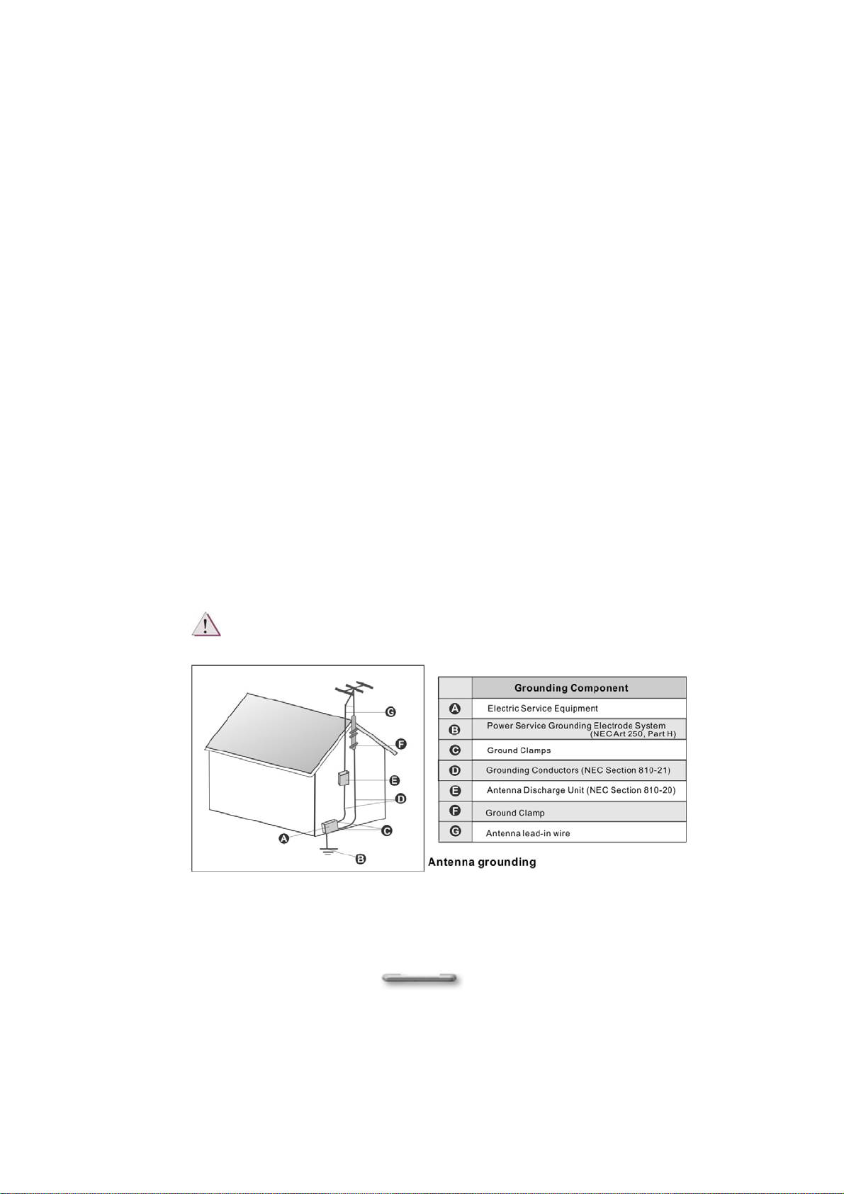
External television antenna grounding
If an outside antenna or cable system is to be connected to the product,
make sure that the antenna or cable system is electrically grounded to
provide some provide some protection against voltage surges and static
charges.
Article 810 of the National Electrical Code. ANSI/NFPSA 70, provide
information with regard to proper grounding of the mask and supporting
structure, grounding of the lead-in wire to an antenna discharge unit, size of
grounding conductors, location of antenna discharge unit, connection to
grounding electrodes, and requirements for the grounding electrode.
Lightning protection
For added protection of any product during a lightning storm or when it is
left unattended or unused for long periods of time, unplug the product from
the wall outlet and disconnect the antenna or cable system.
Må Kun tilkoples kabel-TV nett via galvanisk isolator.
CATV Cable Safety
Make sure that your CATV system installer has connected the Coaxial
8

cable shield to the grounding system of the building, as close to the point of
cable entry as practical.
TV Antenna
The TV antenna supplied with any TV Tuner module is intended for Indoor
use only. Please do not use your TV Tuner module outdoors.
9

Table of Contents
Chapter1 11
Unpacking 11
Checklist:........................................................................................................ 11
Chapter2 12
System Overview 12
Front Panel..................................................................................................... 12
Rear Panel .....................................................................................................13
Chapter3 16
Assembling / Disassembling 16
Removing the Case Cover.............................................................................16
Removing of Hard Disk Rack.........................................................................17
Removing of ODD & Card Reader Frame...................................................... 18
Removing the VGA Card................................................................................ 19
Removing the Power Supplier........................................................................ 20
Installing/Uninstalling the Hard Disk Drive .....................................................21
Installing/Removing the CPU .........................................................................22
Installing Foot Stand.......................................................................................25
Appendix 26
System Specifications 26
Product Features............................................................................................ 26
Technical Specifications................................................................................. 27
Motherboard Placemenet Chart..................................................................... 28
10

CChhaapptteerr11
UUnnppaacckkiinngg
Before unpacking the C2D900+ System, prepare a suitable workspace for your
computer. Provide a steady, level and clean surface, near an electrical wall outlet. Also
ensure that the computer has enough space around it to allow for airflow, especially at
the rear of the computer near the fan. If the computer does not have enough
ventilation, internal components can become overheated and may become damaged.
When opening the box of the computer, make sure not to damage the box, as you may
need to keep it and all packing material for future shipping needs.
Unpacking the box, make sure the following components are included in the box and
are in good condition. If you find that any of these components are missing or appear
damaged, please contact the system dealer immediately.
Checklist:
C2D900+ System Unit
;
AC Power Cord
;
CPU Heat Sink
;
HDD Cable
;
This Assembly Guide
;
;
;
;
;
CD-ROM Cable (Optional)
Support Software Drivers
Application Software (Optional)
Main Board User’s Manual

CChhaapptteerr22
SSyysstteemm OOvveerrvviieeww
Front Panel
The features in the front panel are shown in Figure 2.1, and are described as following.
Figure 2.1
1. Power switch:
Let’s turn the C2D900+ System on or off. When power on, this LED embedded in
Power switch will light blue. If the button is held down for one second, the unit will
enter Suspend mode, and if held down for four seconds, unit power will switch off.
2. HD LED:
When this LED lights yellow, it indicates that the hard disk is being accessed at
the moment.
3. Line Out jack (light green):
Connect audio devices such as headphones or speakers to this jack.
4. Microphone jack (pink):
Plug the microphone into this jack for recording or voice-control functions.
5. USB port x 2
Two USB devices can be connected via these ports; there are a further four on
the rear of the computer – see below.
12

Assembling / Dissmebling
6. IEEE1394 Connector
1394 devices can be connected via these ports.
7. Air Inlet
This inlet allows air inside or outside chassis to be inhaled and exhaled for better
air-flow.
8. ODD device:
Insert DVD-ROM into this drive for enjoying multimedia data.
9. 8-in-1 Card Reader:
Allows users to access and read a variety of memory cards directly from front
panel.
Rear Panel
The features in the rear panel are shown in Figure 2.2, and are described as following.
Figure 2.2
1. COM1 port (turquoise):
Connect serial (RS232) devices such as a modem to this port.
2. VGA port :
Connect VGA devices such as a display monitor to this port.
3. USB port x 6
Connect USB peripheral devices to these ports to take advantage of the
universal functionality and flexibility of Plug and Play technology. You can also
connect USB-Keyboard or USB-Mouse.
4. HD 2.1 Channel Audio
13

Line In jack (blue):
Connect audio sources such as tape players to this jack for recording on your
computer or playback through the Line Out device.
Line Out jack (green)
Connect audio devices such as headphones or speakers to this jack.
Microphone jack (pink):
Plug the microphone into this jack for recording or voice-control functions.
5. Power socket:
Connect the power cord to this socket, ensuring that it is connected to a stable
AC power source.
! CAUTION:
Before you plug the AC power cord, you must first check the voltage toggle switch
setting is appropriate for your geographical area.
6. Parallel port (purple):
Parallel devices such as a printer or scanner can be connected to this port.
7. IEEE1394 Connector
High-speed 1394 devices (such as hard disk or video camera) can be connected
via this port.
8. RJ45 LAN connector
For connecting with your LAN to access the network services or surf the Internet.
About Security Mechanism
For safety purpose, this unit features with specific design in providing you full protection of this
machine.
Figure 2.3
14

Assembling / Dissmebling
1. Chassis Lock:
A hardware security mechanism, when you place the switch in lock position, the
chassis cover cannot be opened.
2. Kensington Lock:
A hardware security mechanism, which locks the chassis to prevent hardware
from being stolen.
3. Pad Lock:
A hardware security mechanism, which can lock up the chassis with lock to
prevent being opened.
4. Chassis intrusion:
A hardware security mechanism, once the chassis cover be opened, the Chassis
intrusion will be touched and will automatically notice the BIOS system.
15

CChhaapptteerr33
AAsssseemmbblliinngg // DDiissaasssseemmbblliinngg
Removing the Case Cover
! CAUTION:
C2D900+ is design 100% tool less with a special disassemble knob.
Please reference to this lable to open the chassis.
i. Lay the unit flat face the rear panel of the unit.
ii. Switch the Chassis Lock to unlock cover position, as shown in Figure 3.1
Figure 3.1
iii. Pull the cover forward slightly then lift it upwards and outwards from the back of the
unit to remove it as shown in Figure 3.2.
Perform the above steps in reverse order to replace the cover.
16
Figure 3.2

Assembling / Dissmebling
Removing of Hard Disk Rack
i. Before removing the whole hard disk rack from the main body, please disconnect
the flat cable and power cord of the hard disk, as shown in Figure 4.1, and Figure
4.2.
ii. Switch the Chassis Lock to HDD unlock position, as shown in Figure 4.3. and
remove the hard disk rack by simply disengage metal tab that connects to main
frame,
Figure 4.1
Figure 4.2
Figure 4.3
17

Removing of ODD & Card Reader Frame
i. Remove the front cover with disengaging metal tab that hook on bottom and move
it forward to open it.
Figure 5.1
ii. Before removing ODD & Card Reader frame from the main body, you must first
disconnect the card reader connector, SATA port and power connector, as shown
in Figure 5.2
Figure 5.2
18

Assembling / Dissmebling
iii. Hold up the shield plate (as indicated by below drawing circle) and pull forward,
you may totally opened the ODD & card reader rack, as shown in Figure 5.3.
Figure 5.3
Removing the VGA Card
i. Lift up the VGA board shield plate from the main braket, as shown in Figure 6.1.
Figure 6.1
19

ii. Disengage metal tab that stepped with main bracket as indicated in step1, and
slightly move the VGA board to right side as indicted in step 2 to unhook the board
from staple.
Figure 6.2
Perform the above steps in reverse order to install the VGA card.
Removing the Power Supplier
i. Pull up the switch to unlock the power supplier, as shown in Figure 7.1.
Figure 7.1
ii. Disengaged the power supplier from the main frame, as shown in Figure 7.2.
20

Assembling / Dissmebling
Figure 7.2
Installing/Uninstalling the Hard Disk Drive (Only for Office
/ Premium SKU)
i. Hook your hands inward onto the plastic holder (as indicated in below drawing step
1) and then lift it upward from the hard disk rack (as indicated in below drawing step
2), as shown in Figure 8.1.
Figure 8.1
21

ii. Pull the plastic holder outward a bit for removing the hard disk, as shown in Figure
8.2.
Figure 8.2
iii. Fix the hard disk rack in position by simply placing it back to main frame, as shown
in Figure 8.3.
Figure 8.3
Installing/Removing the CPU
i. Remove the CPU heat sink before removing the CPU. To remove the CPU heat
sink from the main body, you must first disconnect the Power connector, CPU
front fan and rear fan connectors, as shown in Figure 9.1.
22

Assembling / Dissmebling
Sys_Fan
Connector
ii. Unscrew the heat sink from motherboard, as shown in Figure 9.2.
Figure 9.1
Figure 9.2
iii. Orient the CPU with the socket, place the CPU on socket, it should slide into
place without the use of force.as shown in Figure 9.3.
CPU_Fan
Connector
Power
Connector
23

Figure 9.3
iv. Pull down the socket lever and click it into its latch at the side of the socket, as
shown in Figure 9.4 above, to lock the CPU in position.
Figure 9.4
v. Place the heatsink back to motherboard, and scre w each side of the heatsink,
there are 4 holes in total, as shown in Figure 9.5 below.
Figure 9.5
24

Assembling / Dissmebling
Installing Foot Stand
The footstand is intended for the C2D900+ to stand securely in the upright position.
Please assemble it on the chassis, as shown in Figure 10.1 and Figure 10.2
Figure 10.1
The C2D900+ System with the foot stand which can keep the C2D900+ up and stable
during use.
Figure 10.3
Figure 10.2
25

SSyysstteemm SSppeecciiffiiccaattiioonnss
Product Features
Drive bays
Front Panel
Back panel
Expansion cards
AAppppeennddiixx
• Slim Super Multi x 1
• 3.5” standard HDD drive x 1
• Card Reader drive x 1
• Switches: Power Button
• Creative Window:
USB port x 2
IEEE1394 port x 1
Line out jack x 1
Microphone jack x 1
• LED Indicators:
Power-On/Off & Suspend activity indicator
HDD activity indicator
• USB port x 6
• RJ45 LAN connector x 1
• D-Sub VGA port x 1
• Mic In, Line in, Line Out x 1
• Parallel port x 1
• Serial port x 1
• AC x 1
• Rear: Low-profile PCIe16x slot x 1
• Internal: miniCard slot x 1 (optional)
26

Assembling / Dissmebling
Technical Specifications
Dimensions
Power Supply F/F
Slots & Sockets
BIOS Management System BIOS:
• 320mm (D) x 290mm (H) x 85mm (W)
• Standard LFX 220W with PFC
• Socket 775
• DIMM Sockets x 2
• PCI Express X16 Slots x 1
• Power connector
• Battery socket
• Award BIOS
System BIOS compliance:
• ACPI 1.0b (S0, S1,S3, S4, S5)
• APM 1.2
• PnP 1.0a
• SMBIOS 2.3
• DMI 2.1
• WfM 2.0
• USB 2.0
• Serial IRQ support for PC Card
• Chassis intrusion detection
• TPM support
• AMT support
• VT support
Power Management:
• PCI PME support
• Power failure recovery
• USB Keyboard and mouse wake up
• Remote on/off /Suspend to HDD
• WOL/WOR
Manageability
• Hard disk fault prediction (S.M.A.R.T)
• Remote control management
All contents in the specifications are subjected to change without notice.
27

Motherboard Placemenet and Specification
28

Project Name PTC-Q965
CPU
- Type Socket 775 processor
- Model Smithfield (95W) / Conroe (65W)
- Vendor Intel
Assembling / Dissmebling
- VRM
- FSB 1066/800/533 MHz
Chipset
Memory
IDE - Number NO
S-ATA - Number 4 ports / 2 ports
Graphics - Interface Embedded
IEEE 1394 VT6307S (or VT6307L)
Audio
I/O Chip
Expansion
- Vendor Intel
- North Bridge Intel Broadwater Q965
- South Bridge Intel ICH8DO
- Flash (SPI) 16Mb (for AMT2 and BIOS)
- DIMM Socket 240pin DDR2 DIMM socket *2
- ECC Support N/A
- Type DDR2 533/667/800
- Max Memory Support 1 GB for each channel / 2GB total
- Controller High Definition Audio 2.0 codec
- Codec Realtek ALC260 2 Channels
- Onboard Amplifier N/A
- Controller Nineveh Gb LAN LAN
- AMT Support Yes, support AMT2
- Chip ITE
- AGP8X/PCI/ISA/CNR 1* PCIeX16
Mainstream FMB (65W)
FMB 2006 Mainstream: FMB(06B)、65W
Option: FMB(05B) 、130W
(dual channel)
BIOS
- PCI/ CNR Shared N/A
- MiniCard (Mini PCIe) 1 (optional)
- Vendor Award legacy BIOS as default
29

Power
Management
PCB
Rear I/O
Front I/O
Internal
I/O connector
- Power Connector ATX 24 pin+ 12V connector
- Fan 4-pin CPU_FAN * 1, SYS_FAN*1
- Energy Lake (QRT) No
- Form Factor Pico BTX
- Layer 4 Layer
- Size Standard pBTX size
- USB USB *6
- VGA/Serial/Parallel 1* VGA /1*Serial/1*Parallel
- Audio/Gameport N/A
- LAN (RJ45) RJ45
- Modem (RJ11) N/A
- 1394 Yes
- Diagnosis LED LAN Activity, Follow SAMSYNC default
- Front USB Port (2x5) 2 ports/2 x Pin Header
- Front Memory Stick N/A
- Front Audio(2x5) Yes (Mic-in, Headphone) HD Audio
- 1394 Yes
- FDD (2x17) No
- HDD (2x20) No
- CD Audio Input (1x4) 1
- USB (2x5) 2
- IEEE1394 (2x5) 1
- AUX IN (1x4) N/A
- Telephony (1x4) N/A
- SPDIF (1X3) 1
- Onboard Audio 1
- On Board Buzzer Yes
- TV-out/DFP N/A
- Chassis Intr (1x2) 1
- IrDA N/A
- COM2 (2x5) N/A
- SCSI No
30

Assembling / Dissmebling
Certification
- Front Panel (2x5)
- PCIe Pin header N/A
- Jumpers CLR_CMOS (1-2: Normal, 2-3: Clear CMOS)
- LPC (2x7) for BIOS
debug
- ITP/XDP for CPU
debug
- Energy Lake No
- EMI/ Safety CE
- PC99 color connectors Yes
- OS Supported Windows XP, MCE, Vista
- TPM TPM 1.2 Others
- HDD Activity LED
- ON/OFF/Suspend LED on Front Panel
- Single/Dual Color LEDs definition
1
1 (not stuff)
WHQL - Logo
PC2001, Energy Star, USB (report ready)
31
 Loading...