

Page 1
INSTALLATION / OPERATION MANUAL
FSTB-A SERIES BREWERS
FSTB-A60
*FSTB-A60C
Length 20-1/2
Height 16-7/8
Width 9-7/8
1430 Watts
12 Amps
120 Volts
*Model includes carafe
P. O. Box 3150•Columbus, OH 43213-0150
OASIS CORPORATION
265 N. Hamilton Road
1-800-64-OASIS (1-800-646-2747)
www.OasisWaterCoolers.com
FSTB-A80
Length 20-1/2
Height 21-1/2
Width 10-1/4
1430 Watts
12 Amps
120 Volts
Manual PN 30099-256
Page 2
CAUTION: READ INSTALLATION / OPERATION INSTRUCTIONS PRIOR TO
INSTALLATION INSTRUCTIONS
A. INSPECTION
Brewer comes complete with brew basket, detachable power cord and installation/operation manual (carafe may be
included, but is sold separately).
1. Inspect the carton and brewer for evidence of rough handling and concealed damage. Damage claims should be
filed with the carrier.
2. Remove top cover.
3. Remove float cap assembly from the feed reservoir. Inspect float arms to ensure they are moving freely (shipping
may cause floats to catch against the side of the float cap). If float arm is caught, pull arm down and ensure it is
moving freely.
4. Replace float cap assembly to the feed reservoir.
5. Check that the spray head tube from the solenoid valve to the spray head is securely connected (see Figure 8).
6. Replace top cover.
B. CONNECTING WATER SUPPLY TO BREWER
IMPORTANT: Unit must be installed on a water line with water pressure between 20 PSI and 90
PSI. If water pressure exceeds 90 PSI or has the ability to spike beyond 90PSI a
pressure regulator should be installed.
1. Place brewer on a level surface.
2. Insert water supply tube into external fitting (see figure 1). Brewer is equipped with an external fitting (located at
rear) capable of accepting a 3/8” tube.
NOTE: Brewers are shipped with a plug in the external fitting. Plug must be removed before installin g the water
supply tube.
PLASTIC TUBING
• Cut tube ends square and straight. Do not deform the tube (i.e., cause tube to compress its diameter so it is
• Make sure the outer surface of the tube is clear of marks or scratches for a length equal to twice the tube
• Avoid sharp changes in direction when routing the tubing. Sharp turns cause the tubing to flex and deform
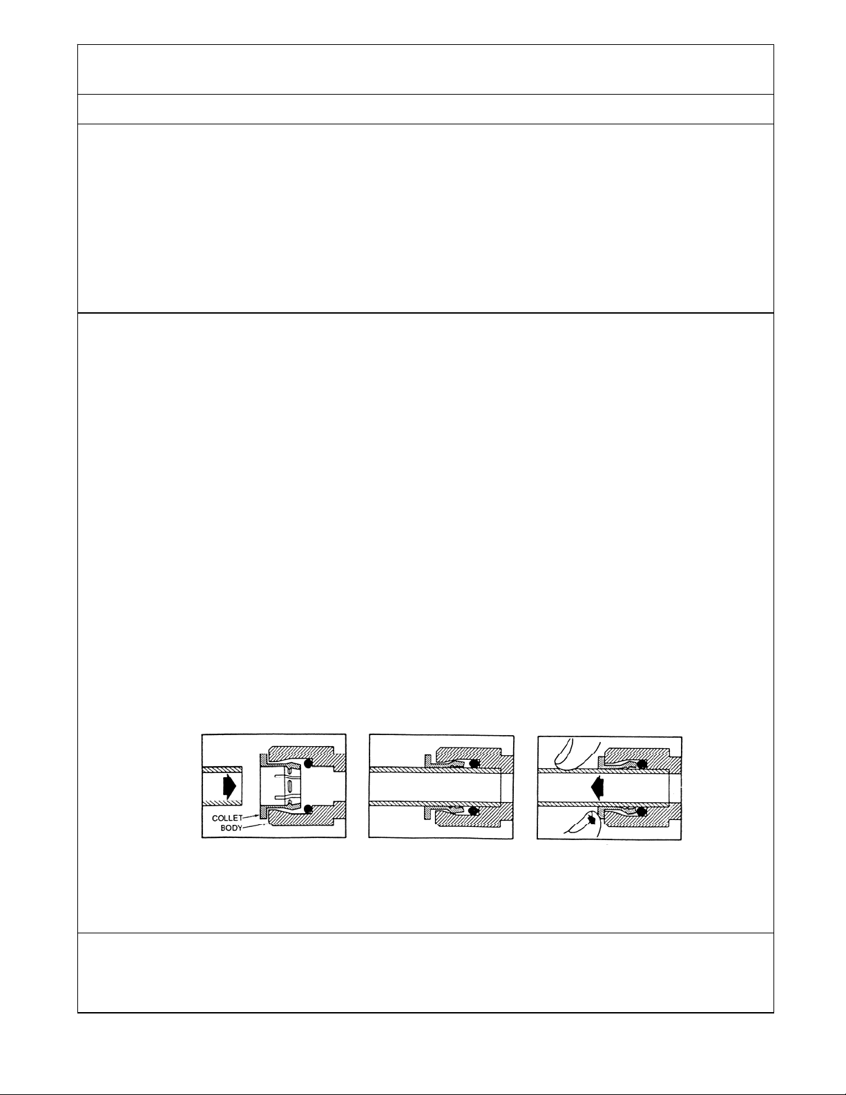
QUICK-CONNECT FITTINGS
• Fittings consist of two parts: a body and a collet (See Figure 1).
• To install a tube, push it through the collet until it seats firmly at the bottom of the fitting.
•
C. ELECTRICAL CONNECTION
Figure1
How to Use Quick-
Connect Fittings
3. Open water supply. The tank will immediately begin to fill. Tank fill time is approximately 3-5 minutes and is
complete when the sound of flowing water has stopped.
1. When tank has completed the water fill cycle, insert the IEC side of the electrical cord into the receptacle at the
rear of the brewer.
2.
Plug the three prong electrical cord in 120 Volts outlet capable of carrying 15 AMPS – 1600 Watts.
INSTALLING AND OPERATING THE FRESHSTART BREWER
Flush water line prior to installing brewer. Brewer should be connected to a COLD
WATER LINE.
no longer round).
diameter. This allows the “O” ring to seat properly against the tube (See Figure 1).
which reduces its flow capacity.
To remove a tube, push and hold the collet against the body while pulling the tube out.
Push tube through Collet into Body
Tube must seat firmly at bottom of fitting
Push Collet against Body to
release tube
Page 3
WARNING: WATER TANK MUST BE FILLED BEFORE PLUGGING MACHINE INTO
V
OLUME PROGRAM PROCEDURE
A. ENERGIZE BREWER / HOT TANK HEAT UP
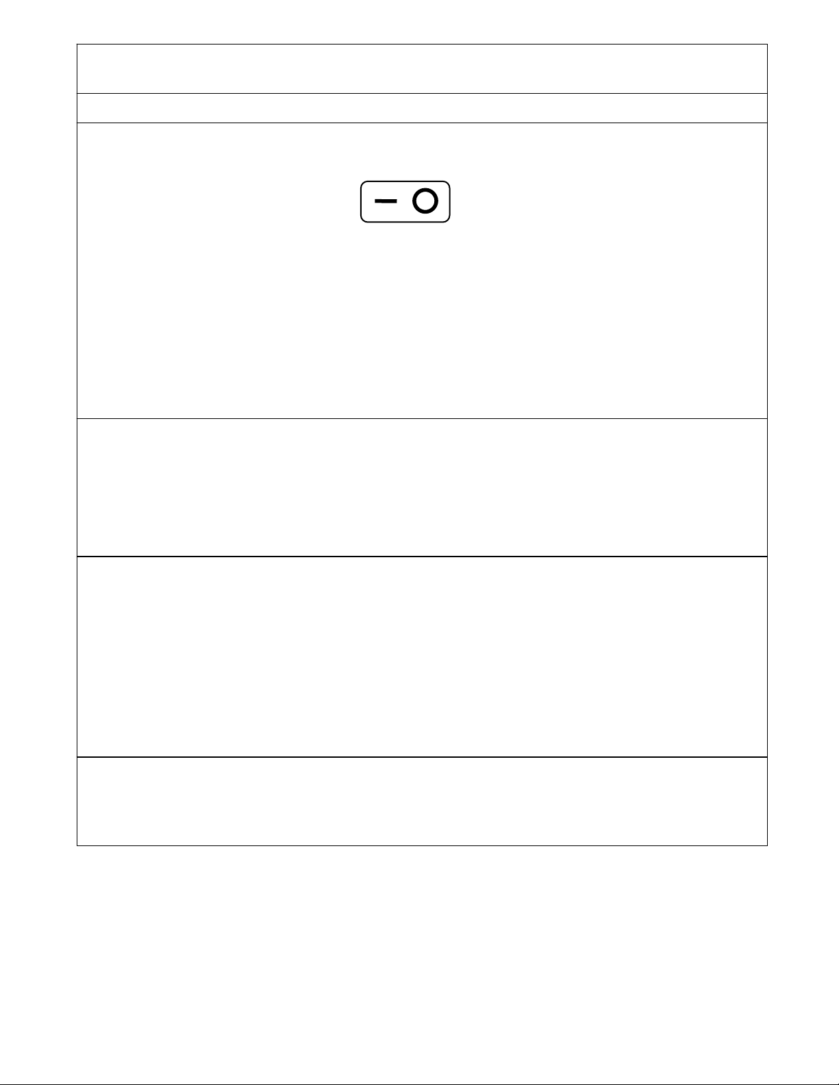
1. To power up brewer and start the hot tank, push the ON/OFF MAIN POWER switch, at rear of the brewer, to the
ON position (See Figure 2).
2. Turn the front control panel on by pressing the ON/OFF BREW CANCEL button. The red light above this button
will illuminate indicating that the front control panel in on.
3. Hot tank must reach full temperature. From a cold start, final temperature will be reached in 10-15 minutes and is
indicated when the green OPTIMUM WATER TEMPERATURE light is illuminated.
4. Once hot tank has reached final temperature, the expanded water must be released. To do so, place the
appropriate empty carafe into position under brew basket, start a brew cycle by pressing the BREW (FULL POT)
button and let it run for about (20 seconds). To stop the brew cycle, press the ON/OFF BREW CANCEL button.
NOTE: Brewer is pre-programmed at the factory for a (6 oz.) brew cycle. Program procedure must be
B. INITCIATE VOLUME PROGRAM PROCEDURE
1. Make sure power is shut off to the brewer by pushing the ON/OFF MAIN POWER switch to the OFF position.
2. Press and hold down the BREW (FULL POT) button on the front control panel.
3. While holding down the BREW (FULL POT) button, push the ON/OFF MAIN POWER switch at the rear of the unit
to the ON position.
4. Once the ON/OFF MAIN POWER switch has been pushed to the ON position, the BREW (FULL POT) button can
be released.
The brewer is now in the volume set up mode and is indicated by a flashing red light ab ove the BREW (FULL POT)
button.
C. PROGRAM POT SIZE
1. Remove brew basket.
2. Place measuring pitcher on base under the spray head (spray head must be attached for accurate volume).
3. Press the BREW (FULL POT) button to start water flow (red light will continue to blink).
4. Allow measuring pitcher to fill to the required volume.
5. Press the BREW (FULL POT) button to stop water flow when it has reached the required volume.
6. Press the BREW (FULL POT) button again to lock the volume into memory.
NOTE: Programmed volume will remain in memory even with lose of power or if unplugged, until the volume
Half pot function is automatically calculated and set to exactly half of the programmed volume.
CAUTION: THE FILTER LOCATED ON THE FLOAT CAP MUST REMAIN
ELECTICAL OUTLET
ON OFF
ON/OFF MAIN POWER switch illustration (switch
completed to set required pot volume.
program procedure is initiated and volume is reprogrammed.
COMPLETELY DRY AT ALL TIMES. TAKE SPECIAL CARE IN
TRANSPORTING A BREWER WITH A FULL UPPER RESERVOIR AS IT
MAY CAUSE THE FILTER TO GET WET.
Figure 2
located at rear of brewer)
Page 4

OPERATION INSTRUCTIONS
A. BREWING COFFEE
1. Remove brew basket from brewer.
2. Place one (1) standard commercial filter (9.5 inch
B. CANCELLING A BREW CYCLE
C. CUP DRAW FROM SAFTEY FAUCET
diameter) into brew basket.
3. Put required amount of coffee grounds into filter and
shake brew basket to level off coffee grounds.
4. Return brew basket to brewer.
NOTE: Brew basket is designed to click into
place when properly installed. This action
secures the brew basket to the cabinet.
5. Place appropriate EMPTY thermal carafe into position
below the brew basket.
6. Press the BREW (FULL POT) button for full pot volume
or the BREW (HALF POT) button for half pot volume.
NOTE: The corresponding light above the chosen
BREW button will blink for the duration of
the brew cycle. When light has stopped
blinking, the brew cycle is complete and it
is safe to remove the carafe.
7. After brewing is complete, remove brew basket and
discard used coffee grounds and filter.
8. Rinse brew basket and return to brewer.
To cancel a brew cycle that is in process, press the ON/OFF BREW CANCEL button located on the front control
panel. When canceling a brew cycle, water is shut off to the spray head, but the brew basket will continue to drain
until depleted.
CAUTION: WATER FROM SAFETY FAUCET IS HOT
To draw a cup of hot water from the safety hot faucet (red button
located on the front panel of the brewer):
1. Place an empty cup directly under the non-textured bump
2. Push the red button down and forward to start the flow of
3. When finished, release button. Button will return to original
out located directly under the CAUTION HOT WATER label
(see figure 4).
hot water.
position and hot water will stop flowing.
Filter/Coffee
Placement
Brew Basket
Figure 3
Brew Basket Illustration
Figure 4
Safety Faucet Illustration
Page 5

SERVICE INSTRUCTIONS
r
A. ADJUSTING HOT TANK THERMOSTAT
Whenever thermostat adjustment becomes
necessary, complete the following procedure:
1. Disconnect power cord from electrical
outlet.
2. Remove (2) screws and rear panel (see
figure 5).
3. Use a bladed screwdriver to adjust the
thermostat knob (see figure 5). Turn
clockwise for hotter water temperature
and counter clockwise for cooler water
temperature.
4. Replace rear panel and (2) screws.
5. Plug power cord into electrical outlet and
follow steps 1-3 in ENERGIZE
BREWER/HOT TANK HEAT UP
B. CLEANING THE SPRAYHEAD
Over time mineral build up may develop around the
(6) spray holes on the spray head which may lead to
pot volume variances. Periodic inspection and
cleaning of the spray head is recommended.
1. Turn spray head counter clockwise a quarter
turn until it stops (see figure 6).
2. The spray head and the brew basket rail will
drop straight down to remove.
3. Remove gasket from spray head when cleaning.
4. Reassemble spray head and brew basket rail
using reverse procedure. Make sure spray
head detents (clicks) into place when
reassembling.
C. REMOVING HOT TANK ASSEMBLY FROM CABINET ASSEMBLY
1. Turn the main water supply to brewer OFF.
2. Disconnect the power cord from both the electrical outlet
and the IEC plug located at the rear of the brewer (see
figure 5).
3. Disconnect 3/8 inch supply tube from quick tube connect
(see Figure 5).
NOTE: If hot tank is full, water will dribble from the
4. Remove cover from cabinet assembly.
5. Remove (2) screws and rear panel (see figure 5).
6. Pull drain tube out rear access opening.
7. Remove plug from end of drain tube.
CAUTION: HOT WATER WILL IMIDIATLY FLOW
8. Remove ribbon cable for circuit board.
9. Let tank completely drain of water.
10. When finished draining tank, replace the drain tube plug.
11. Remove silicone tube from hot water faucet fitting.
12. Remove molded silicone tube from spray head top.
13. Remove (2) screws from rear switch plate (see figure 5).
14. Remove hot tank assembly from cabinet by lifting from
external tube fitting. It is recommended that
the fitting be plugged with the provided 3/8
inch plug.
FROM DRAIN TUBE.
the upper plastic reservoir (see figure 7).
3/8” Quick Tube
Connect
Thermostat
Adjustment Knob
Brew Basket Rails
Spray Head Gasket
Spray Head
Assembly
Assembly
Cove
Hot Tank
Cabinet
Rear Switch Plate
Screws (2)
Figure 5
Figure 5
Thermostat Adjustment Illustration
Thermostat Adjustment Illustration
Figure 6
Spray head removal Illustration
Figure 7
Hot Tank / Cabinet Assembly
On/Off main
power switch
IEC Cord
Receptacle
Rear Panel
Hot Water
Faucet Outlet
Opening
Page 6

D. SERVICING THE MECHANICAL FLOATS
Anti
r
r
A
r
Resetting the Safety Float
1. Remove cover from cabinet.
2. Press down on the safety float
re-set button (see figure 8).
Float arm inspection
1. Remove float cap from top
reservoir.
2. Float arms should move up and
down freely and should not bind
or catch (see figure 9).
E. INSPECT AND REPLACE CIRCUIT BOARD FUSE
1. Disconnect power cord from electrical outlet.
2. Remove cover from cabinet.
3. Locate fuse at the lower right side of the circuit board (see
figure 8) and inspect the fuse filament for breakage.
4. If fuse appears to have blown, carefully remove it from the
circuit board and check it for continuity.
5. If fuse is blown, replace it with a 25 volt, 5 AMP, slow blow
fuse.
F. INSPECT AND REPLACE DUMP SOLENOID VALVE
1. Disconnect power cord from electrical outlet.
2. Remove cover from cabinet.
3. Locate dump solenoid (see figure 8) and visually inspect clear
solenoid valve body for mineral build up or debris.
4. If build up or obstruction has occurred, remove the hot tank assembly
from the outer cabinet (see section C).
5. Remove both sets of wires from the solenoid valve.
6. Remove from the solenoid valve both the silicone tube from the hot
tank and the angled silicone tube going to the spray head.
7. Remove the dump solenoid by loosening the two screws that hold it to
the bracket assembly. Once the screws have been loosened, the
solenoid valve can be removed from the bracket slots (see figure 10).
8. If replacement is required, assemble a new or refurbished dump
solenoid valve in the reverse order.
Air filte
Safety float
re-set button
Circuit Board
Open Cover
G. THERMOSTAT REPLACEMENT
Primary Thermostat (see figure11)
1. Disconnect the power cord from both the electrical outlet
and the IEC plug located at the rear of the brewer (see
figure 5).
2. Remove the hot tank assembly from the outer cabinet (see
section C).
3. Remove both wires from the anti boil thermostat.
4. Loosen tie wire and remove the rear half of the insulation
from the hot tank.
5. Using an 11/32
threaded weld stud. Nut secures thermostat and cover.
6. Remove thermostat cover.
7. Remove thermostat from threaded weld stud.
8. Remove both wires from thermostat.
9. Replace using the reverse order as above.
NOTE: When threading the nut back to the weld stud (the
reverse of step 5) a torque value of 18 inch pounds must be
applied for proper assembly.
-Boil Thermostat (see figure 11)
1. Follow steps (1-4) from Primary Thermostat.
2. Using a ¼ inch nut driver remove both screws from bracket.
3. Replace using the reverse order.
inch nut driver, remove nut from thermostat
Figure 8
Solenoid
Valve
Spray Head
Tube
Loosen Solenoid
Screws (2)
Primary
Thermostat
Primary Thermostat
Cove
Mechanical Float Cap Assembly
Figure 10
Dump Solenoid Valve
Limite
Control
Figure 11
Thermostat Locations
Figure 9
nti-Boil
Thermostat
Page 7

G. THERMOST AT REPL ACEMENT (CONTINUED)
Limiter Control (see figure 11)
1. Follow steps 1 and 2 from Primary Thermostat.
2. Remove tank feed and vent silicone tubing from
H. INSPECT AND REPLACE HOT FAUCET
reservoir bottom.
3. Remove upper reservoir by releasing the (3) clips.
4. Remove both wires from limiter thermostat.
5. Using a ¼ inch nut driver remove both screws from
bracket.
6. Replace limiter control using the reverse order.
Mineral build up may occur over time causing a
slower than normal flow rate from hot faucet.
Periodically inspect the faucet outlet (see figure
6) for mineral build up. Also check for mineral
build up, obstruction or kinking of the silicone
tube from the hot tank to the hot faucet. If build
up is abundant, the hot faucet may need to be
replaced. For replacement see instructions
below.
1. Drain hot tank (see Section C steps 1-8)
2. Remove silicone tube from hot faucet.
3. Remove (4) front panel assembly screws
from inside cabinet.
4. Remove (2) faucet bracket screws from
front panel assembly.
5. Loosen hot faucet nut and remove faucet
from bracket.
6. Replace hot faucet using the reverse
order.
NOTE: If dripping from hot faucet occ urs, the
bonnet (see Figure13) may be too
loose. To tighten, turn bonnet one
quarter turn clockwise.
Remove (4)
Screws
Remove (2)
Screws
Hot Faucet Assembly
Figure12
Hot Faucet
Bonnet
Figure 13
Hot Faucet
I. FLOAT CAP AIR FILTER (see fig ure 8)
NOTE: If brewer is moved while filled with water, splashing from the upper reservoir may cause the air filter on
NOTE: Make sure the air filter is completely dry of before setting the pot volume.
If the filter media inside the air filter is wet during the programming of a pot volume, it may cause variances in pot
volumes for subsequent brew cycles. Make sure the air filter is completely dry of before setting the pot volume.
If the filter media inside the air filter gets wet anytime after the programming of pot volume, it may cause erratic
pot volumes.
the float cap to get wet. When moving or transporting brewers, make sure the tank is drained enough
that the upper feed reservoir is not holding any water.
J. HOT TANK MAINTENANCE
NOTE: Over time the hot tank and hot water ways may develop mineral build up which can narrow waterways
affecting pot volumes and hot faucet draws. Mineral build up may occur sooner or later depending on
the TDS level of the supply water to the brewer.
Page 8

TROUBLE SHOOTING GUIDE
•
•
•
•
•
•
•
Brew Cycle Will Not Start
PROBLEM RESOLUTION
No Hot Water or Not Hot Enough Hot Water
Check that the power cord is properly plugged into the
IEC receptacle located at the back of the brewer (see
Figure 5).
• Check that the power cord is plugged into a proper
electrical outlet (see Service Instructions Section C).
• Check that the power switch is in the “on” position (see
figure 2).
• Check that the water supply line to the brewer is
connected properly and turned on (see Service
Instructions Section B).
• Check/ replace fuse on circuit board (see Service
Instructions Section E).
• Re-set safety float (see Service Instructions Section D).
• Check for mineral build up, clogs or kinks to water lines
and fittings.
• Clean spray head (see Service Instructions Section B).
• Check solenoid valve for mineral build up or blockage
(see Service Instructions Section F).
• Replace solenoid valve (see Service Instructions Section
G).
• Verify that the volume program procedure was completed
correctly according to the manual (see Volume Program
Procedure).
Check that brewer is getting power
• Adjust thermostat (see Service Instructions Section A).
• Replace primary thermostat (see Service Instructions
Section G).
• Replace heating element.
Carafe Overflows
Weak Coffee
Hot Faucet Dripping
Slow Flow Rate from Hot Faucet
Verify carafe is empty before brewing fresh pot.
• Verify supply line pressure – if needed add a pressure
regulator.
• Check that float arms are moving up and down freely and
are not binding (see Service Instructions Section D).
• Check for mineral buildup, clogs or kinks to water lines
and fittings.
• Remove and dry (air) filter (see Service Instructions
Section I).
• Check hot tank for mineral build up (see Service
Instructions Section J).
• Re-set pot size (see Volume Program Procedure).
Adjust thermostat to provide hotter water (see Service
Instructions Section B).
• Clean spray head (see Service Instructions Section B).
• Modify coffee roast, blend, grind or filter.
Tighten hot faucet bonnet one quarter turn (see Service
Instructions Section H).
• Replace hot faucet (see Service Instructions Section H).
Check for mineral build up at the faucet outlet (see
Service Instructions Section H).
• Check for mineral build up, obstructions or kinks to
silicone tube from hot tank outlet to hot faucet (see
Service Instructions Section H).
Dry Coffee Remaining in Brew Basket
Clean spray head (see service instructions section B).
• Sift grounds flat to set filter (see operation instructions
section A).
• Check for mineral build up, clogs or kinks to water lines
and fittings.
 Loading...