

Page 1
WATERFALL INSTALLATION INTRODUCTION
WATERFALLS
DESIGN PREFACE
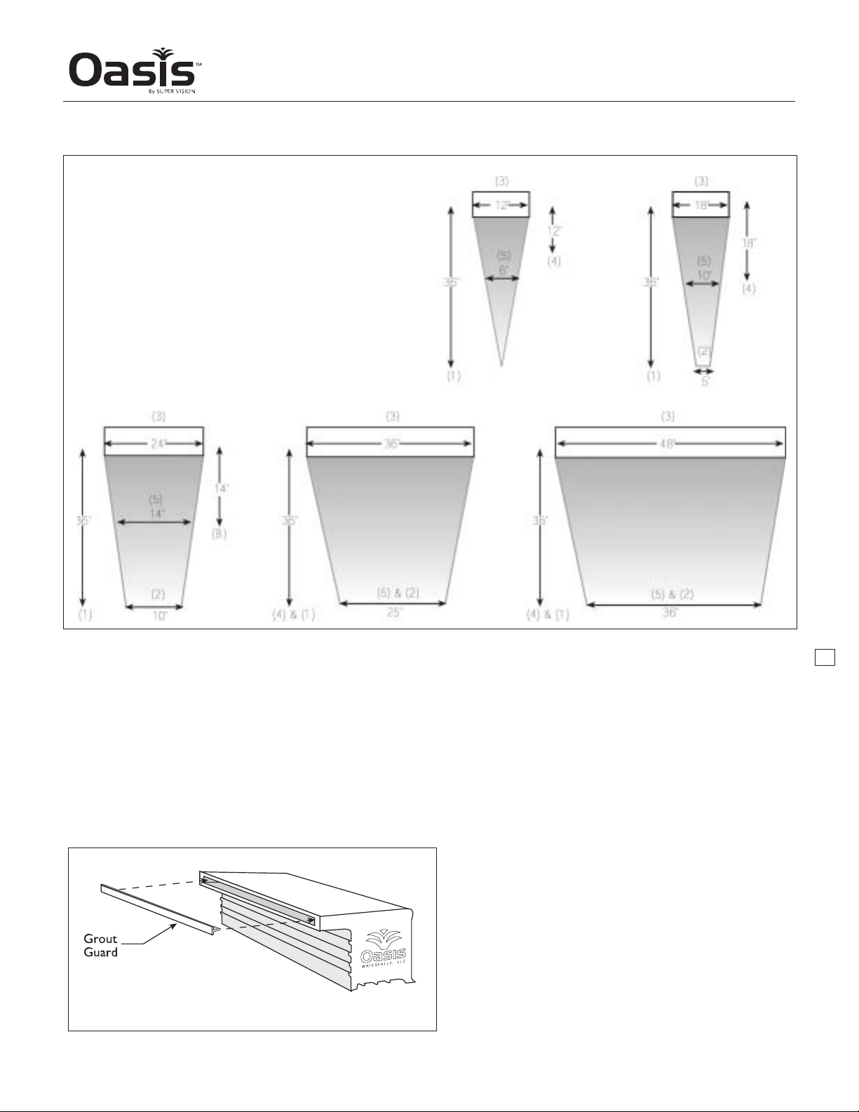
Waterfalls naturally narrow as they fall. Oasis presents
the following waterfall height specifications for this
waterfall unit:
1) Maximum waterfall height.
2) Width of sheet of water at the maximum waterfall height.
3) Length of waterfall fixture.
4) Recommended waterfall height from lip of the
fixture to the pool water surface.
5) Width of the sheet of water at the pool water
surface (when installed at the recommended height
mention in item B).
Thank you for purchasing an Oasis WaterFall. This manual will help you make a trouble free installation.
Please follow the installation recommendations as outlined by the manufacturer.
Please read the entire manual to become familiar with the installation requirements before
installing the Oasis WaterFall.
Important! Do Not Remove the protective grout guard until the installation is complete (See figure 1).
Note: The waterfall must be installed prior to installation of the deck and coping.
The tile installer generally installs the Oasis WaterFall unit.
47
TO ORDER 407.857.9900 or FAX ORDER FORM (PAGE 57) 407.857.0050
Page 2
3
2
1
7 9 10 12 15 20
12
INSTALLATION FOR PVC WATERFALL UNITS
WATERFALLS
HYDRAULIC GUIDELINE CHART
• Use minimum of 1.5” pipe
• Use minimum of 2” pipe for runs in excess of
60’ or if waterfall is over 5’.
• Dedicated plumbing lines are recommended
• Maximum recommended flow for a typical
installation:
1.5” pipe for 60 GPM
2” pipe for 100 GPM
2.5” pipe for 140 GPM
3” pipe for 225 GPM
THE OASIS RAINFOREST FALL™
• The installation is the same as the Original
Oasis Fall™, see installation manual in the
box.
• Make sure pipes are clean before start-up.
• The unit should be installed in line with
pool filter to keep debris from entering the
waterfall.
• Do not exceed 5 gallons per minutes per
linear foot of rainfall.
• Excessive pressure may damage the unit.
•Aball valve should be installed on each
waterfall to control flow.
•To reduce the risk of damage, close ball
valve before start-up and open gradually
until the desired rain effect is achieved.
48
TYPICAL PUMP PERFORMANCE AT 50’ OF HEAD
.5 HP = 26 GPM
.75 HP = 58 GPM
1 HP = 68 GPM
1.5 HP = 93 GPM
2 HP = 106 GPM
3 HP = 140 GPM
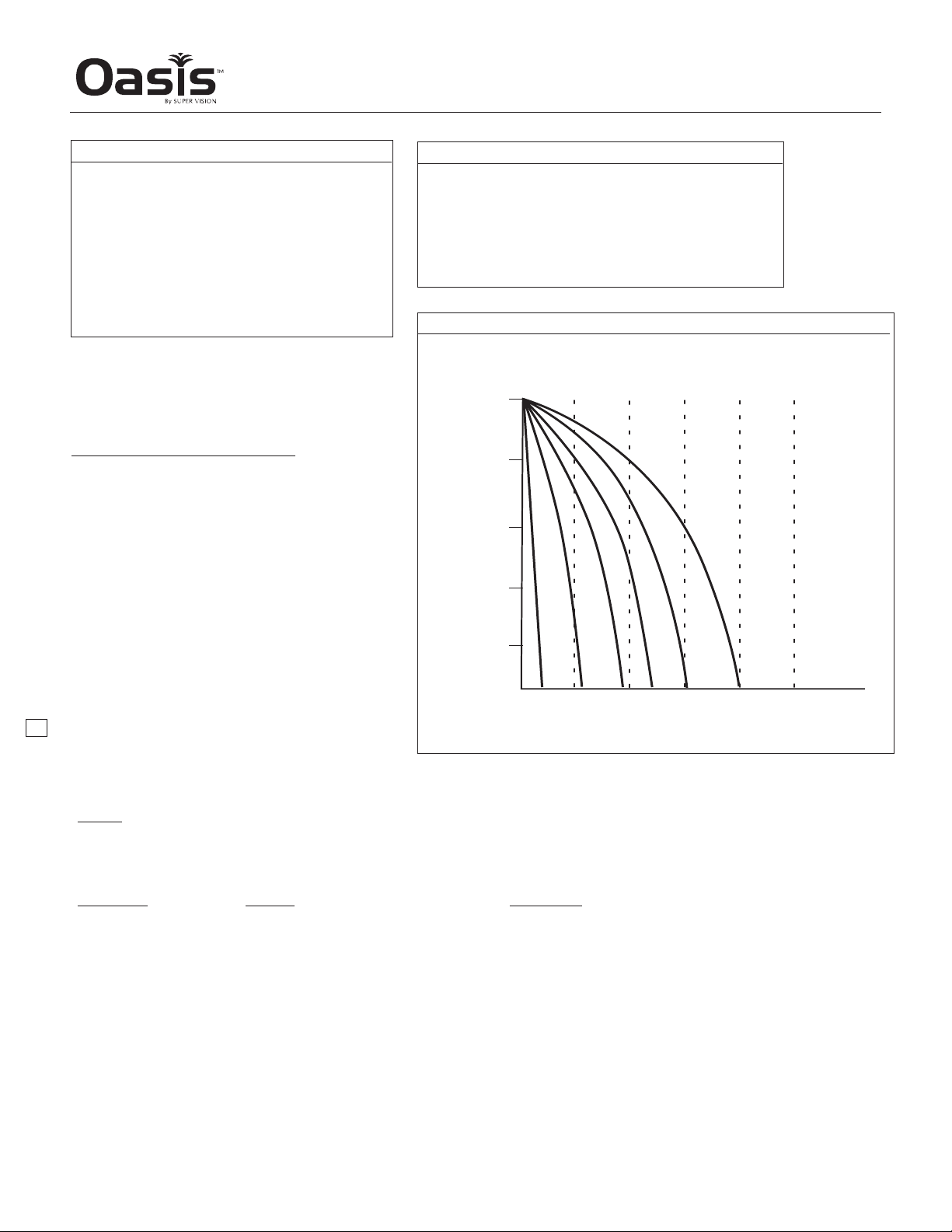
WATER FLOW REQUIREMENT CHART FOR 1’ TO 4’ MODELS
Feet of Projection
Feet of Elevation
Gallons per minute per foot
I
STEP
1. Make sure the pump system is fully functional and active.
2. Make sure all air is purged from the line.
PROBLEM CAUSE SOLUTION
The flow is not smooth Debris in the opening Use a thin object to remove the
Gap in the flow debris by sliding the object
along the opening.
Uneven flow between Improper flow balance Adjust the valves for each unit waterfalls
(multiple waterfall until the desired effect is achieved.
installation)
TO ORDER 407.857.9900 or FAX ORDER FORM (PAGE 57) 407.857.0050
Page 3

INSTALLATION FOR PVC WATERFALL UNITS
STEP I.
Notching the Bond Beam
1. Mark the area prior to excavation with stakes and construction ribbon.
2. Prior to steel installation, mark the exact area for the waterfall.
3. Allow 1 inch on each side and 3.5” below the form for the WaterFall (Example: for a 12” waterfall, offset the steel pattern to
allow for an additional 1" space on each side of the waterfall. For a 12” waterfall: 1”+1”+12” = 14”).
4. Measure 3.5” down from the top of the frame.
5. Offset the steel rebar to allow for the cut in the bond beam.
6. Mark a channel for plumbing the waterfall. For single inlet waterfalls the channel is at the center of the notch. Longer water
falls require more water and thus more inlets. For a 6' to 8' waterfalls, position the waterfall over the bond beam and mark the
locations of the inlets.
7. Make sure the cuts in the Bond Beam are positioned correctly before proceeding.
STEP II.
Installing the Waterfall Unit
Note: The top of the Oasis Fall is where the throat and lip are.
1. Glue and connect a length of 1.5” diameter schedule 40 PVC piping approximately 12” long (or to extend beyond the back of
the bond beam) into the back of the waterfall. This step will allow you to complete the mortar set and complete the plumbing
later. (Refer to STEP III-Plumbing before proceeding)
2. Place the Oasis Fall in the pre-cut notch in the bond beam.
3. Level the top of the Oasis Water Fall to the upper edge of the bond beam with tile shims, fill the area below and in back of the
unit with concrete brown coat or similar material.
4. To insure that the waterfall stays in level position until the concrete is dry. Cover the finished setting with 1/2” or 3/4” plywood.
Place bricks or a cinder block on top of the plywood so the weight is evenly distributed over the waterfall and the bond beam.
Check with a level.
Note: This procedure must be always be followed for all installations. Unleveled installation will produce an uneven water flow.
6. When the concrete is dry remove the plywood cover. Before plastering make sure the protective grout guard is in place. Cut
the tile to fit under the lip of the spillway and secure with thin set or a similar compound. Be sure the finished wall surface is
flush with the waterfall lip edge (see Figure 3A).
49
Page 4
RADIUS CUT GUIDE
WATERFALLS
CONCRETE/COPING
DECKING
WATER FLOW
ROCK
TRAP
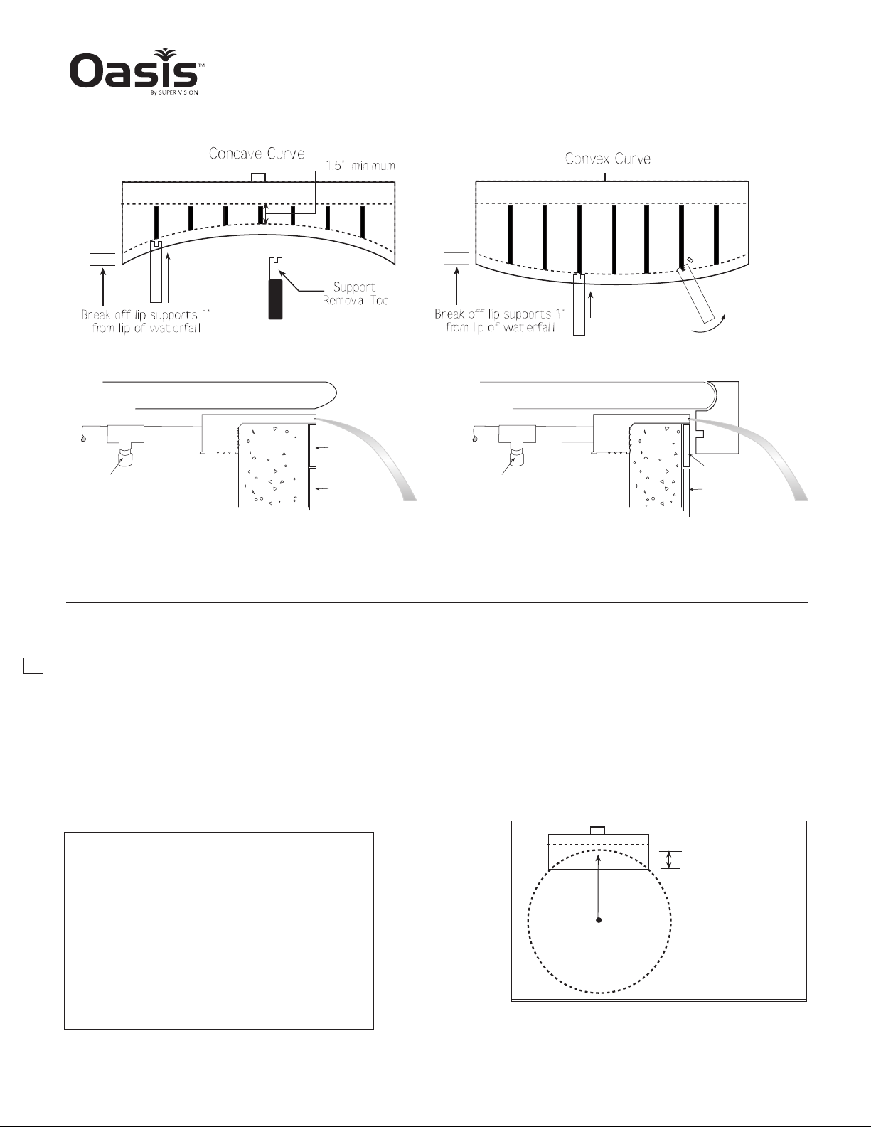
Note: Never remove more than 4.5” of the extended lip, leaving a
50
minimum of 1.5” of lip. The top of the beam, where the Oasis Fall
BOND
BEAM
TILE
PLASTER
COAT
unit is to be installed should be a minimum of 9” thick.
When designing custom curves for the Oasis Falls Extended Lip models, please refer to the following Minimum Radius Table to select the
correct Oasis Falls model. Some models accommodate very tight
radius curves and are available by special order.
CONCRETE/COPING
DECKING
ROCK
FILTER
WATER FLOW
BOND
BEAM
DECK
FORM
TILE
PLASTER
COAT
WATERFALL RADIUS CUT GUIDE FOR PVC
MINIMUM RADIUS PER WATERFALL LENGTH
1' long fall = 1' and up
1.5' long fall = 1.5' and up
2' long fall = 2' and up
3' long fall = 3' and up
4' long fall = 4' and up
5' long fall = 5' and up
6' long fall = 6' and up
7' long fall = 7' and up
8' long fall = 8' and up
TO ORDER 407.857.9900 or FAX ORDER FORM (PAGE 57) 407.857.0050
Do not remove
than 4.5”
radius
Page 5
51
 Loading...