

Page 1
Water Coolers
QUASAR Hands-Free Bottle Filler
UVC-LED WATER TREATMENT
Model PWEBQ and PWF2EBQ (retro fit)
and PG*EBQ Family of Drinking
Fountains/Bottle Filler combo
Installation Instructions
The Hands-Free Bottle Filler mounts directly above Versacooler® I and II
products. If the cooler electrical outlet does not have two useable plugs, an
outlet splitter will need to be used.
If installed onto a refrigerated cooler, chilled water can be dispensed through
the Bottle Filler. Otherwise, room temperature water will be dispensed.
The Bottle Filler is shipped partially assembled.
On the combo units, the cooler is plumbed and ready to attach to the Bottle
Filler.
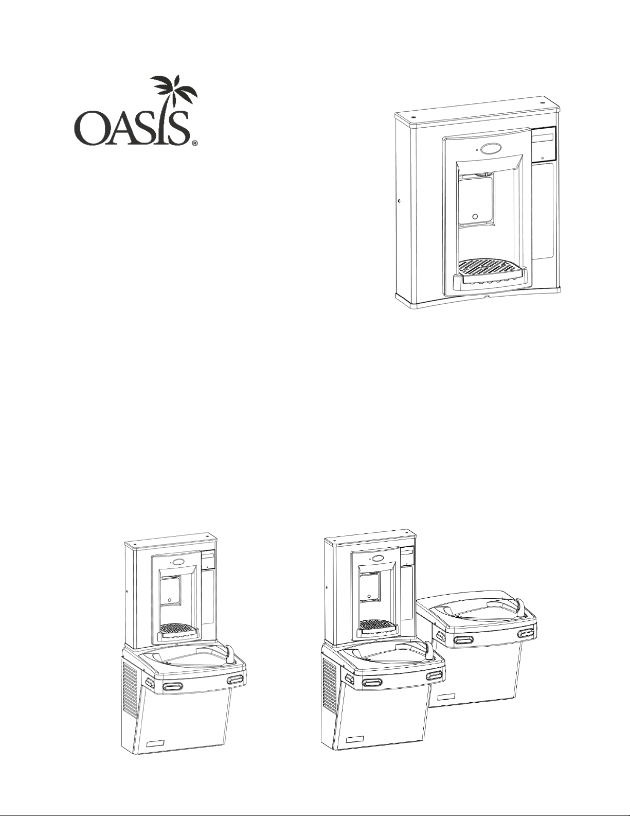
When completed, the finished assembly will look like this:
OR
1
Page 2
Section 1: Getting Started
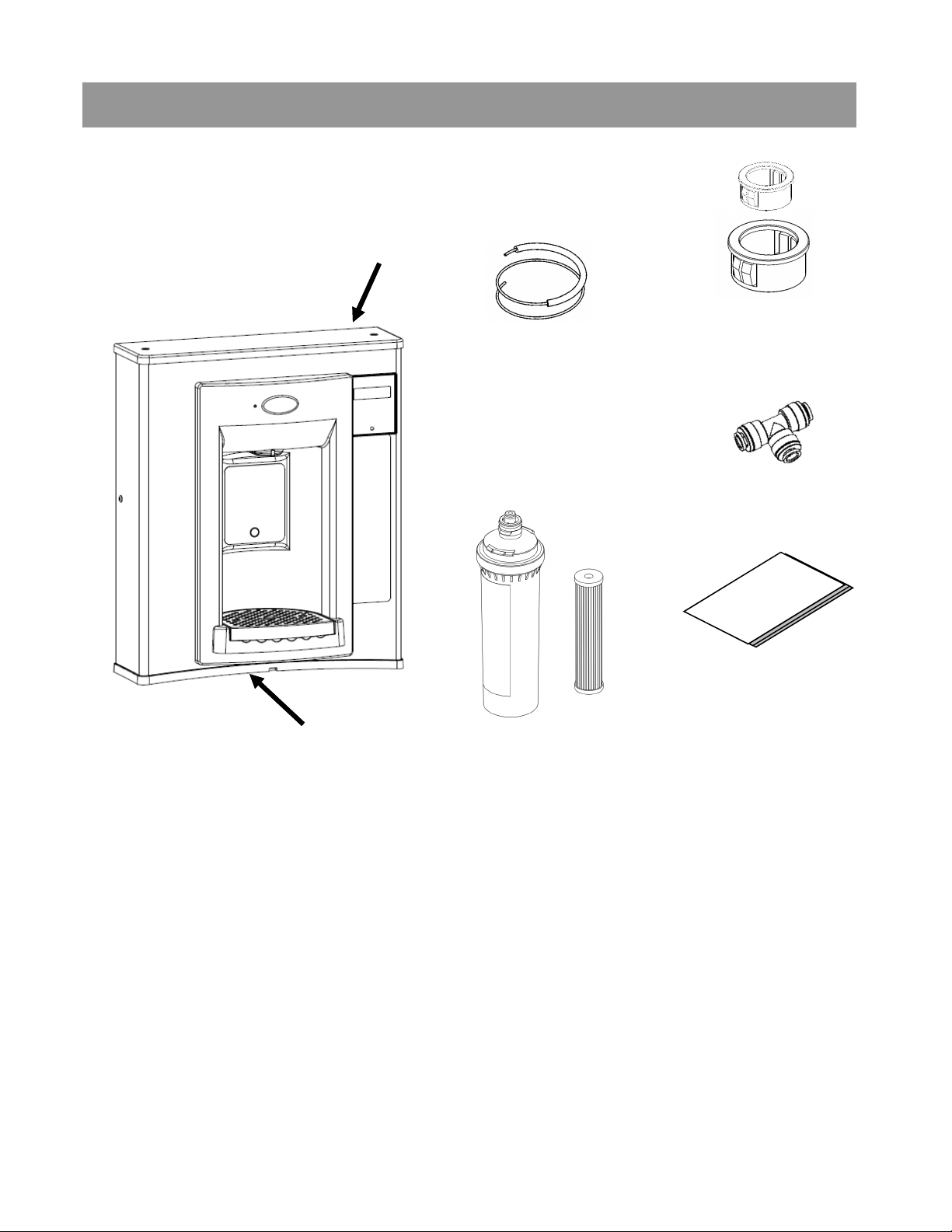
What’s Included:
Top Cap
Quasar Hands-Free
Bottle Filler
38” of ¼ OD plastic
tubing with 19” of
sponge tubing
insulation (included
with “Quasar Bottle
Filler ready” coolers)
Snap bushings 7/8”
and 1½”
Quick connect tee
fitting
Installation
instructions
Rubber
Gasket
Versafilter II
The Versafilter II and remedi filter are only
included in the PWF2EBQ model.
remedi
filter
Tools required:
3/8” pilot drill and either a step drill bit up to 7/8” diameter that will drill
through SS top or 7/8” diameter punch die (retrofit version only)
Electric drill; wrench for punch die
Small tubing cutter for copper tube
1/4“ nut driver
# 2 Phillips screw driver
#15 torx bit driver
2
Page 3
Section 2: Rough In Drawing
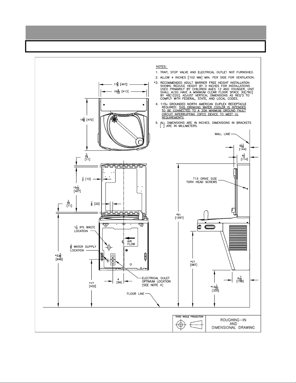
Oasis PWEBQ: Versacooler® II Models PGAC, PG8AC with Hands-Free Bottle Filler
3
Page 4
Section 2: Rough In Drawing
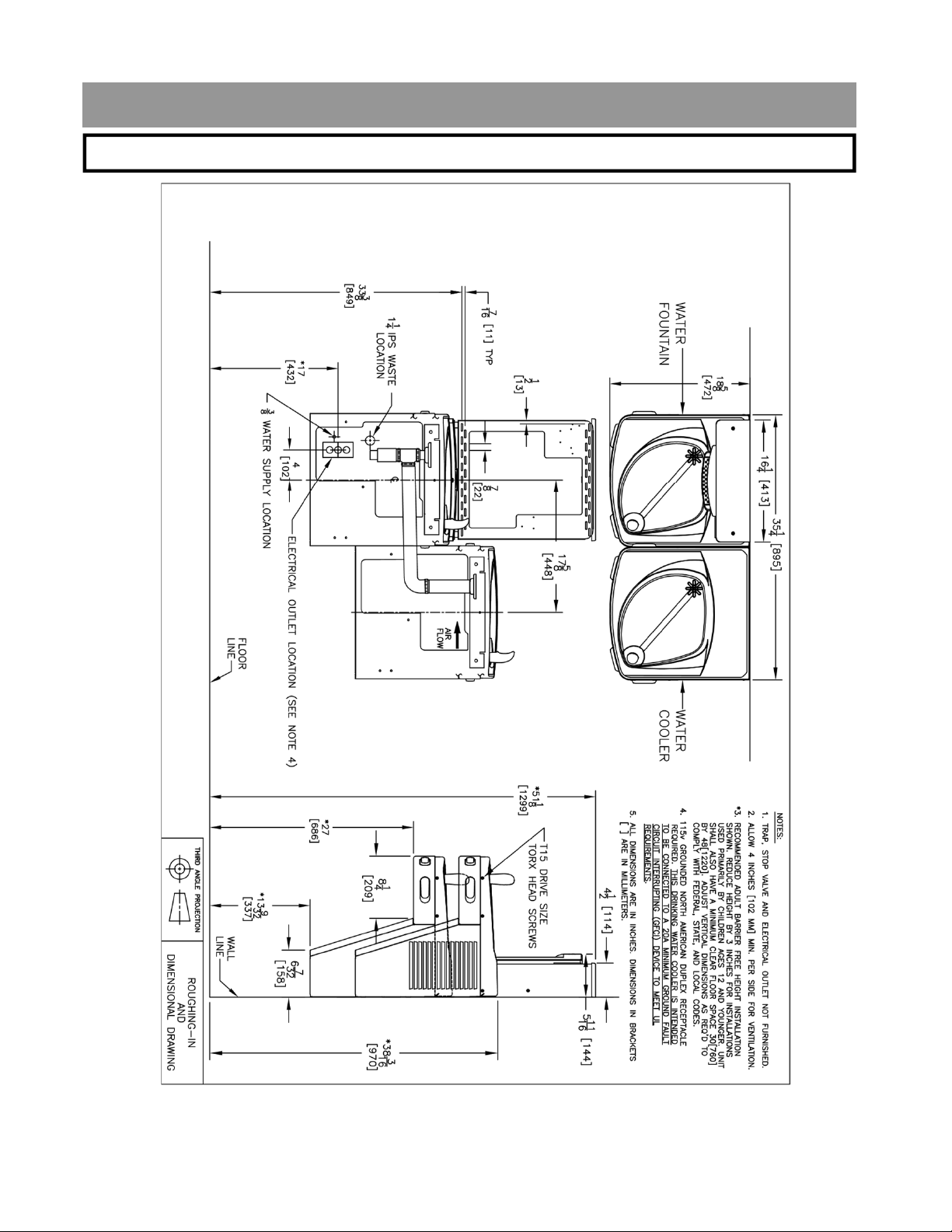
Oasis PWEBQ: Versacooler® II Split Level Models with Hands-Free Bottle Filler
* On split level models, the Bottle Filler must be mounted on the
low unit in order to meet ADA guidelines.
4
Page 5
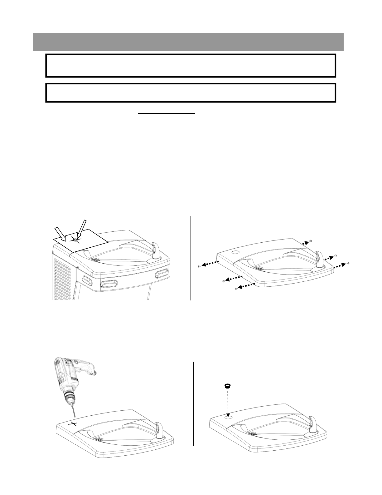
Section 3A: Installation
Note: Proceed to Section 3B Step 5 “Final steps for both product families” if
the cooler is purchased “Quasar Bottle Filler or VersaFiller ready”.
A: Drilling hole in the top for water line connection.
1. Disconnect power by UNPLUGGING unit. It might be necessary to remove
the front panel to get access to the power.
2. Turn OFF water supply to the unit. It might be necessary to remove the
front panel to access the water stop valve.
3. Place hole template onto cooler top so it is aligned with the left side of unit
and wall. SEE NEXT PAGE FOR TEMPLATE
4. Mark hole location
5. Remove top from unit.
Mark hole location.
Template
Remove top from cooler by
removing six, #15 torx head screws
on sides of top.
6. Using a step drill bit or 7/8” punch die, make a 7/8” hole through top. You
may want to drill a pilot hole to get these started.
7. Install snap bushing into hole to protect tubing from being cut.
Install bushing
Drill
5
5
Page 6
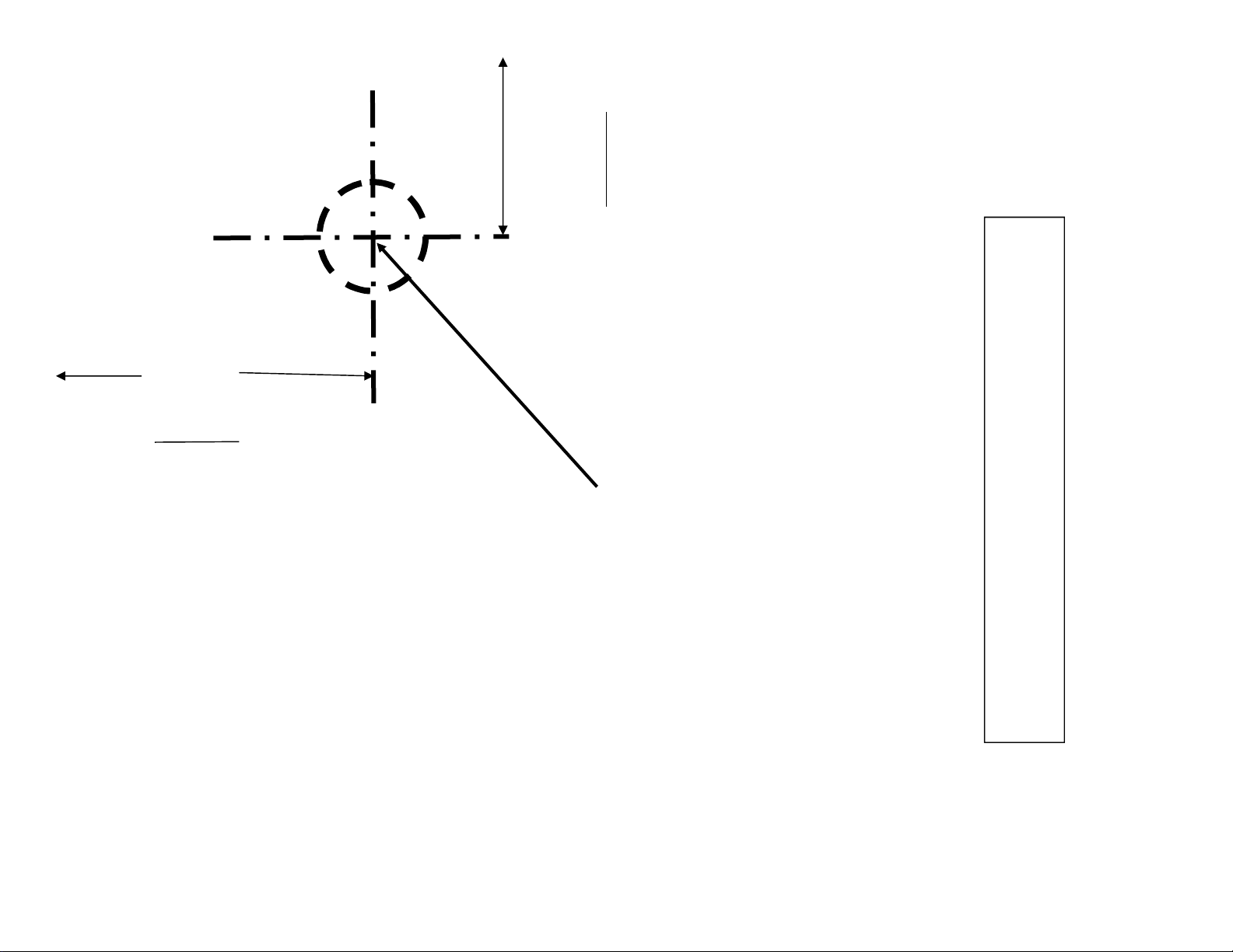
3-1/4”
from
edge of
paper
ALIGN THIS EDGE
WITH LEFT EDGE OF
COOLER TOP
2-1/8”
from
edge of
paper
PLACE THIS EDGE
AGAINST WALL
Mark this center point on the
top. Remove the top from the
6
cooler. Then create a 7/8”
diameter hole through the top
at the marked center point
(step drill bit or punch die).
USE THIS TEMPLATE TO MARK THE
HOLE LOCATION ON COOLER TOP
Page 7
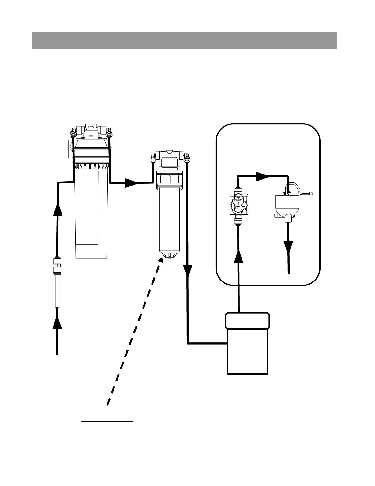
Section 3B: Installation
VersaCooler to Quasar Bottle Filler Plumbing Diagram
OPTIONAL
VERSAFILTER II
INLINE
STRAINER,TUBE,
AND REDUCER FTG.
PROVIDED WITH
FOUNTAIN.
OPTIONAL
FILTER
BOTTLE FILLER
SOLENOID
VALVE
UV LED
BUILDING
INLET WATER
VERSACOOLER
IMPORTANT: When replacing filter cartridge. Turn off
water supply. Depressurize water lines prior removal of
filter housing from the quarter turn filter head assembly.
7
Page 8
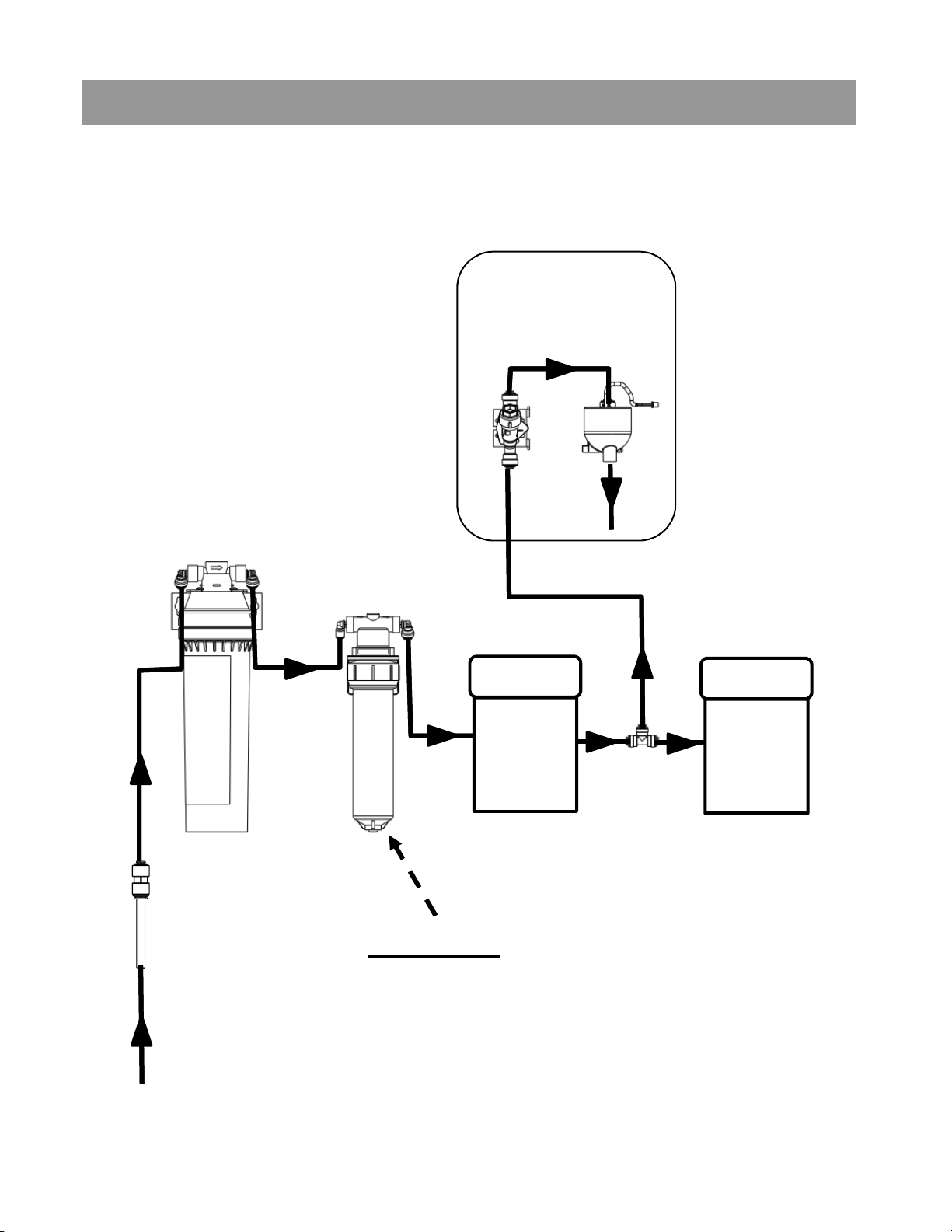
Section 3B: Installation
Two VersaCoolers to Quasar Bottle Filler Plumbing Diagram
BOTTLE FILLER
OPTIONAL
VERSAFILTER II
OPTIONAL
FILTER
SOLENOID
VALVE
VERSACOOLER
UV LED
VERSACOOLER
INLINE
STRAINER,TUBE,
AND REDUCER FTG.
PROVIDED WITH
FOUNTAIN.
BUILDING
INLET WATER
T-FITTING
IMPORTANT: When replacing filter cartridge.
Turn off water supply. Depressurize water
lines prior removal of filter housing from the
quarter turn filter head assembly.
8
Page 9
Section 3B: Installation
B: Connecting the water line
Note: If you are retrofitting the Bottle Filler to an existing
cooler, follow the instructions starting on page 11.
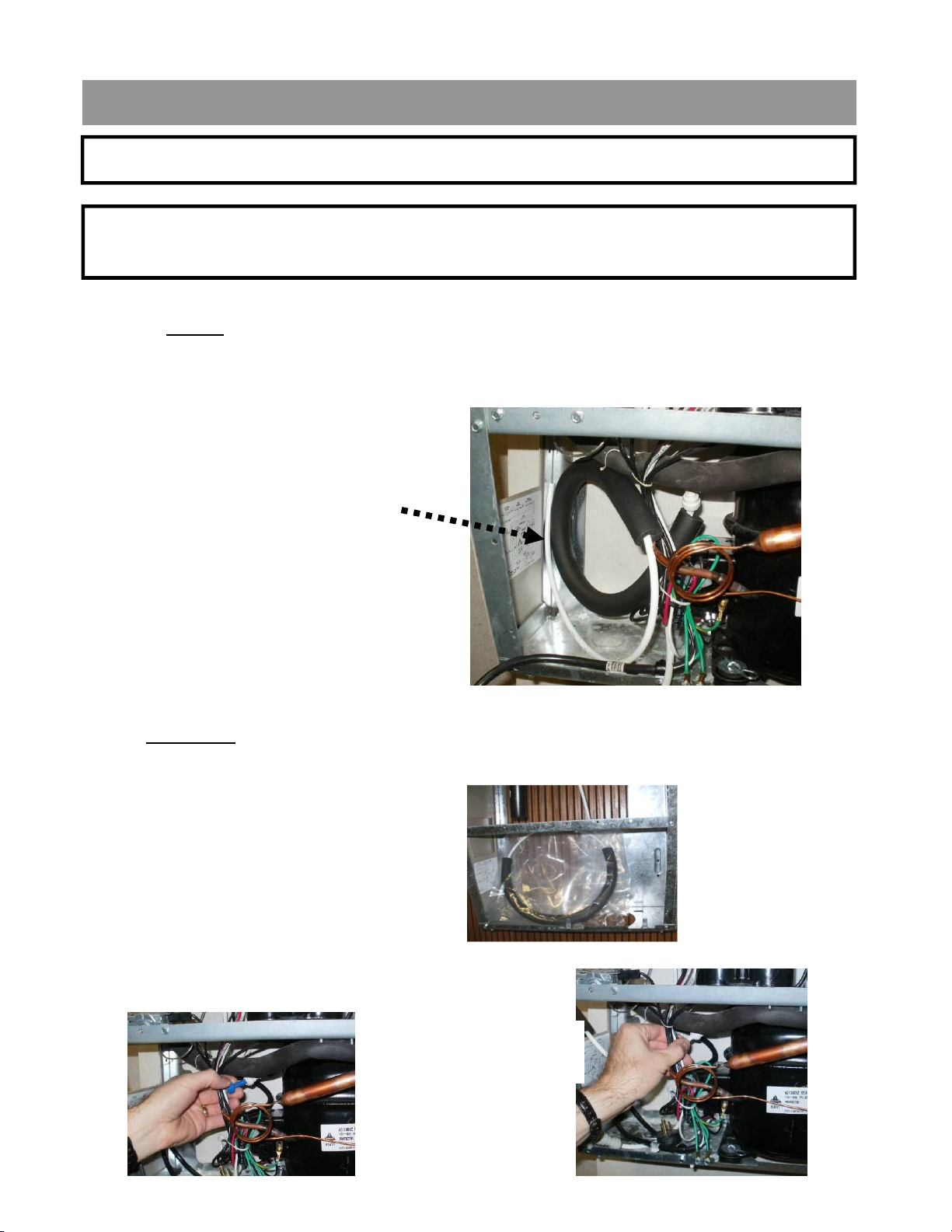
For the single “Bottle Filler ready” cooler, the tube to connect to the Bottle
Filler is found inside the access panel (the compressor compartment). This
tube supplies cold water from the cooling tank to the Bottle Filler.
¼” OD tube to connect
to Versafiller
For split level “Bottle Filler ready” coolers, the tube to plumb in the Bottle
Filler is packaged in the dummy unit.
Remove tube from bag.
First, remove plug from
fitting on tank drain
Next, insert end of
tube into fitting.
9
Page 10
The tee and tube to the Bottle Filler are packaged with the PWEBQ unit.
One branch of the tee will supply the valve on the dummy unit, the other
branch of the tee will connect to the Bottle Filler.
If a filter is being installed, cut a piece of tubing about 3” long to insert
optional flow switch right after filter and before tee. This allows Bottle
Filler counter to accurately calculate amount of water passing through
filter.
Tube to connect valve
on dummy unit
Tube to connect chilled
water to dummy unit
and Bottle Filler
Tube to connect
Bottle Filler
Go to Step 5 “Final steps for both product families:”
10
Page 11
To retrofit the Versafiller to an existing unit, follow the
instructions below:
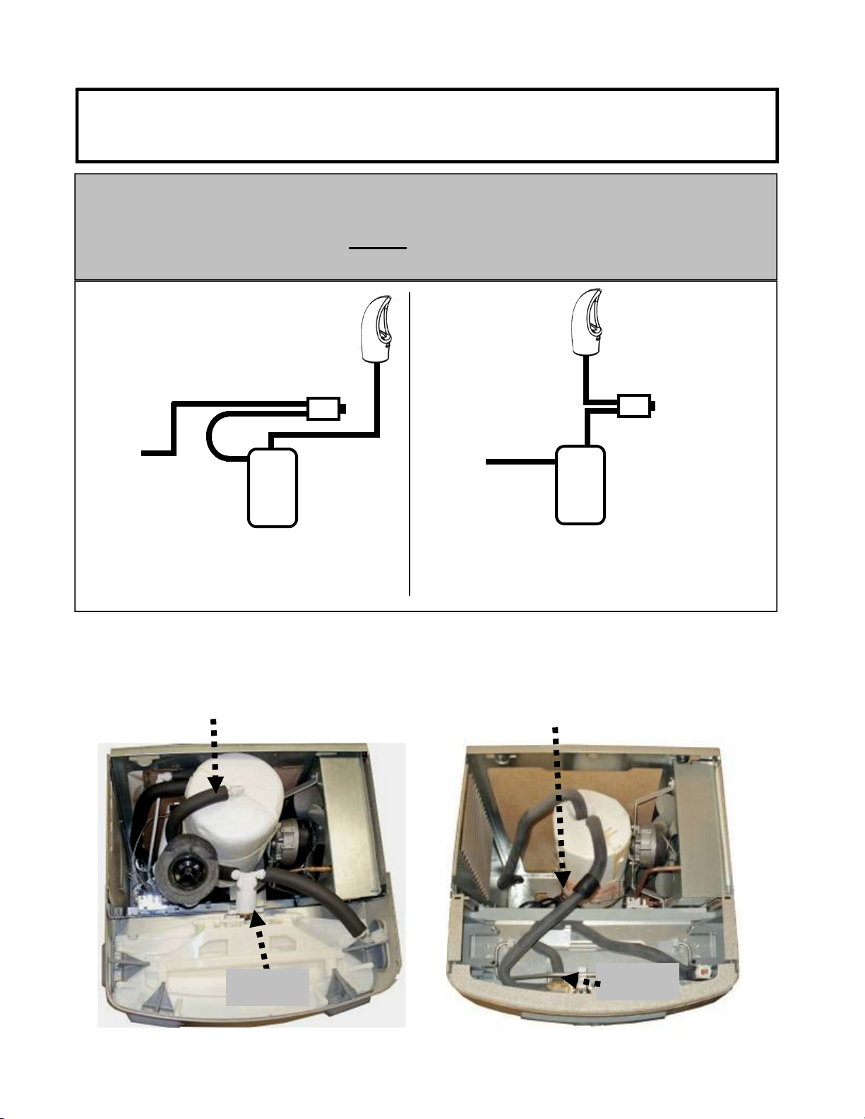
If the cooling tank is non-pressurized, then go to the “Pressurizing the
cooling tank” addendum section. Otherwise, proceed to step 1 below.
Non-pressurized units are single units made since December of 2009.
Refer to the schematic below to identify the system that you have.
Water
valve/
regulator
tank
Supply
Water
Water
valve/
regulator
tank
Cooling
NON-
PRESSURIZED
COOLING TANK
Supply
Water
Cooling
PRESSURIZED
COOLING
TANK
1. With the cooler top removed, find the tube going from the cooling
tank outlet to the valve. The TEE fitting (supplied) will need to
connect between the cooling tank and valve.
Outlet Tube (insulated plastic)
Outlet Tube (insulated copper)
Valve
P8AC family
Valve
P8AM family
11
Page 12
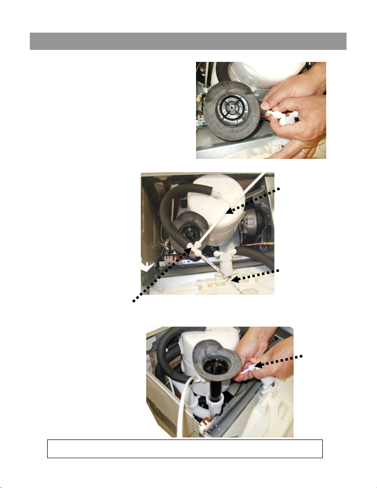
Section 3B: Installation: For the P8AC Version: Versacooler II
2. Disconnect tubing from the
elbow on the valve.
3. Using the 38” piece
of tubing provided,
cut 6” and install it
on the end of the
TEE. Install the
remaining tubing
onto the branch of
the TEE. Connect
the other end of the
TEE to the tank
outlet tubing (tube
that was
disconnected from
the elbow).
TEE
32” tubing
6” tubing
4. Route the TEE and
tubing under the
waste drain and
connect the 6” length
to the water valve
elbow.
Go to Step 5 “Final steps for both product families:”
Water
valve
elbow
12
Page 13
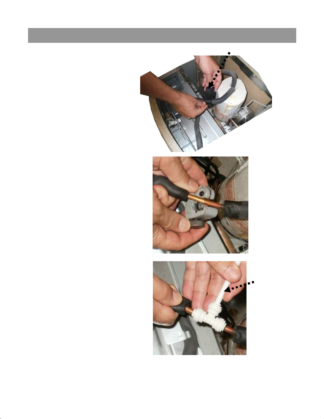
Section 3B: Installation: For the P8AM Version: Versacooler I
Remove tar tape
2. Remove tar tape from
the insulation on the
outlet tube.
3. Pull back insulation and cut
the copper tube with a
tubing cutter. Cut where
there is at least 1 inch of
straight tubing on each side
of the cut.
4. Install TEE fitting by
connecting the copper
tubing to each end. Then
install the 32” piece of
plastic tubing to the TEE
branch.
32” plastic
tubing
(supplied)
13
Page 14
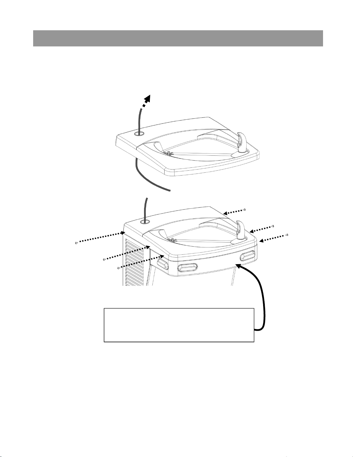
Section 3B: Installation: Final steps for both product families:
5. Feed tube up through the top and attach the top to the cooler.
To solenoid valve inlet.
TIP: For the P8AM, it is easier to
connect the outlet tube to the bubbler if
the front nose is removed.
14
Page 15
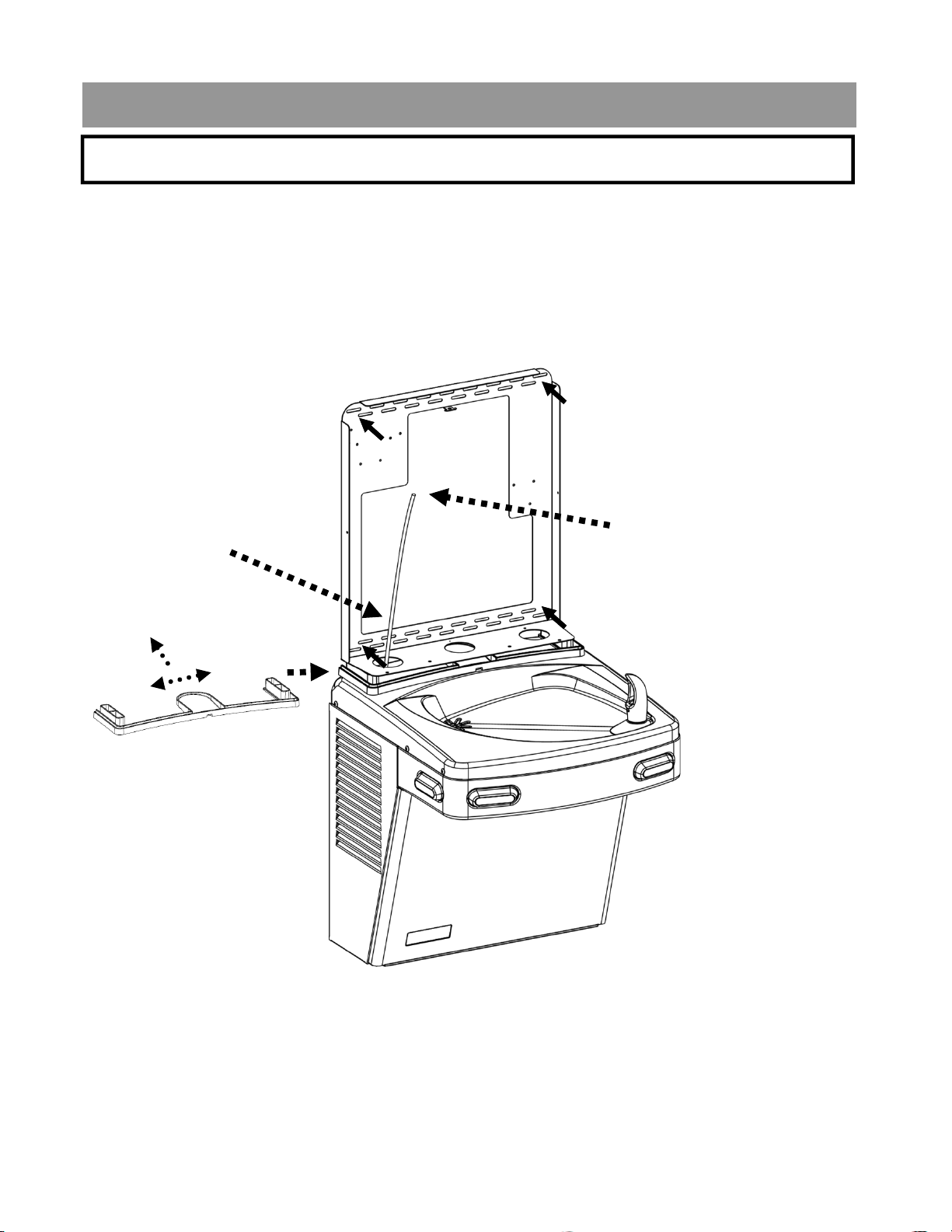
Section 3C: Installation
C: Mounting the frame to the wall
1. Place rubber gasket on top of the cooler so it is centered left/right
and against the wall.
2. Set the wall frame onto the gasket. Center it left/right and push it against
the wall and mark hole locations for wall fasteners. The gasket will set
the frame at the proper height.
Use mounting slots that
will provide the proper
securing location.
Make sure to pull
the plastic tubing
up through the hole
in the frame.
Connects to the
solenoid valve
inlet.
Rubber Gasket
3. Secure frame to the wall with fasteners (not provided). Pull plastic
tubing up through the hole in the frame.
15
Page 16
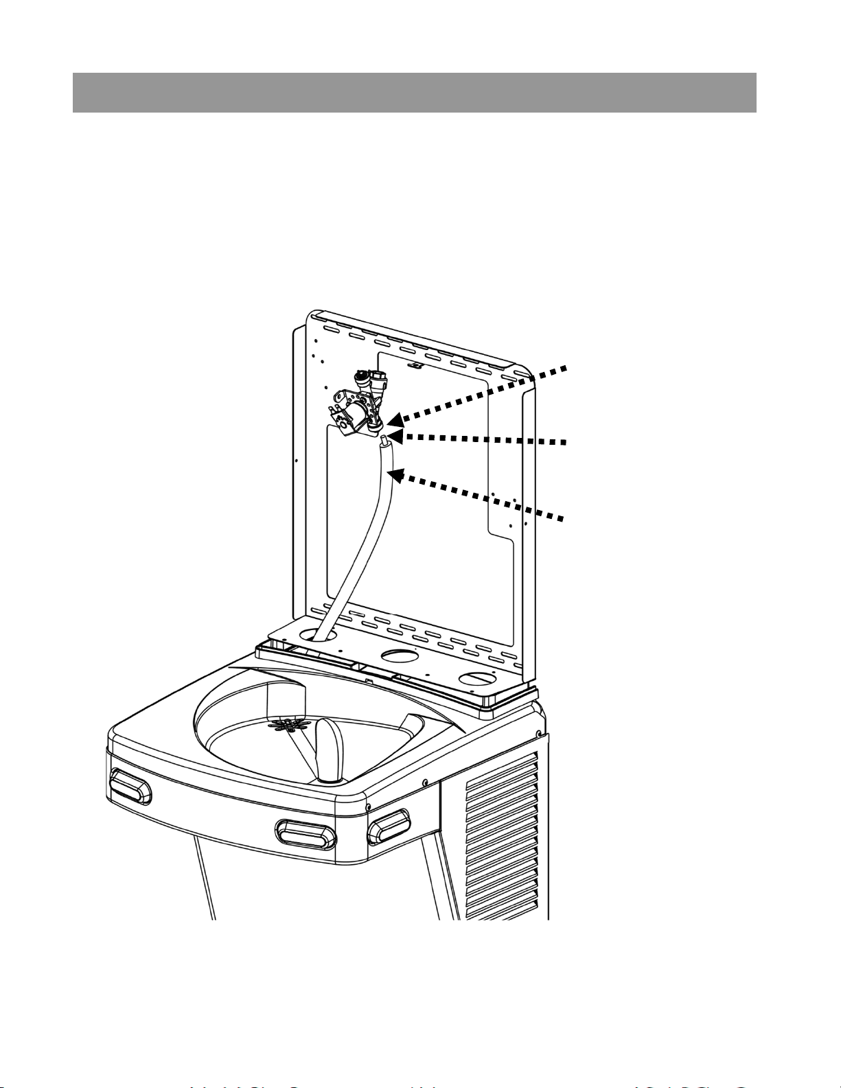
Section 3C: Installation
4. Slide sponge tubing insulation over water line. Connect the tubing to
the INLET of the solenoid on the back of the Hands-free Bottle Filler
assembly.
Connect tube
to inlet of the
valve
Plastic tubing
Sponge tubing
insulation
16
Page 17
Section 3D: Installation
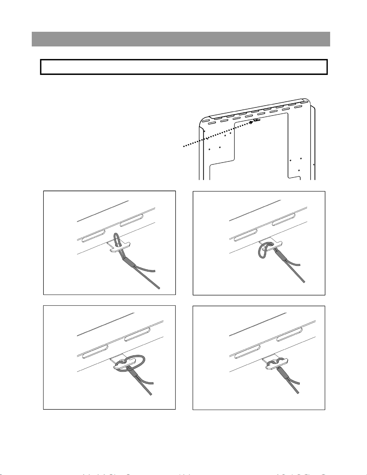
D: Attaching the Tether
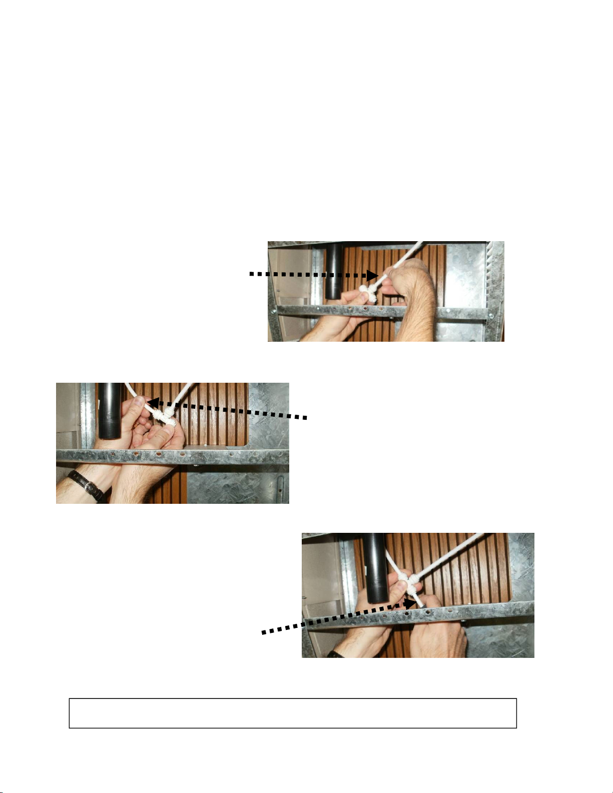
5. Install bottle filler tether with the steps below.
Attach the tether line assembled to the bottle
filler dispense bracket to the cleat on the
mounting frame.
1.
Push loop through hole.
3.
2.
Put loop around one side
of the cleat.
4.
Pull loop around other
side of the cleat.
Pull tight.
17
Page 18
Section 3: Installation
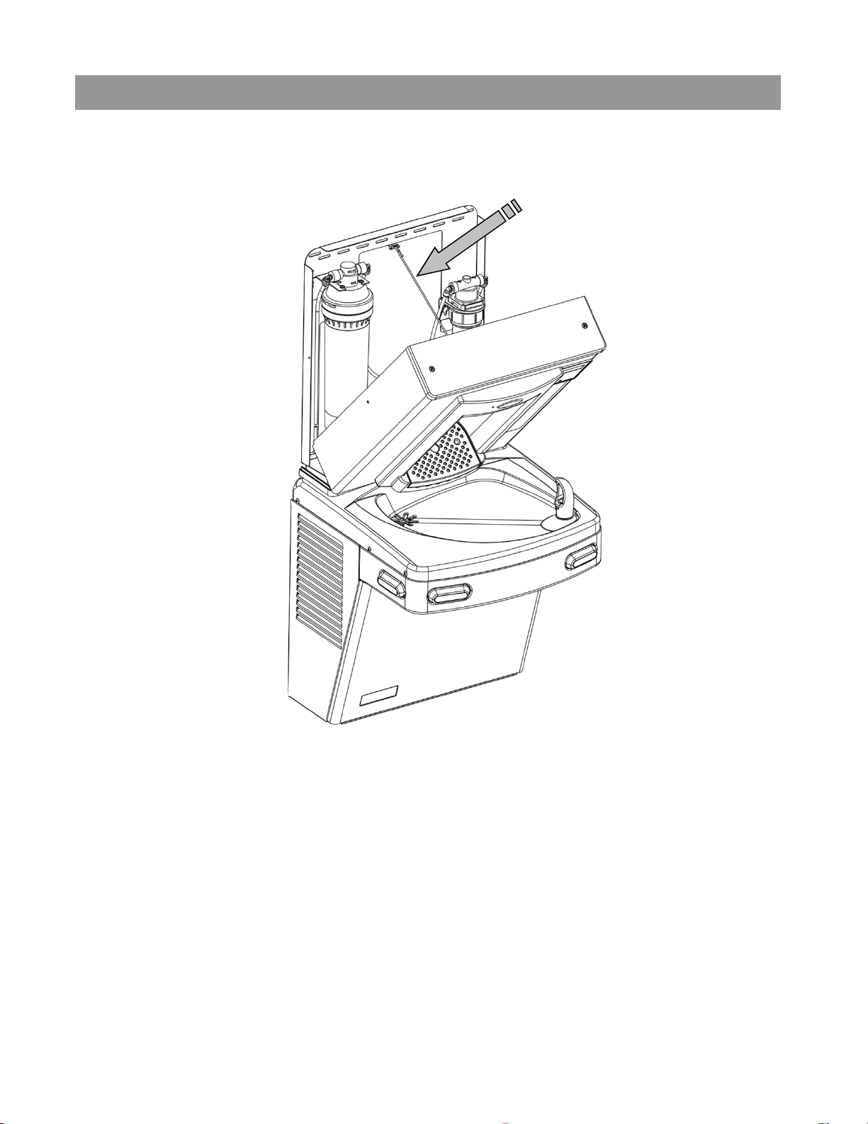
The tether keeps the bottle filler secured to the frame when changing the
filter, if installed. Make sure the tether is installed properly to avoid
accidental damage to the unit.
6. Before the Bottle Filler cabinet is set into place, feed the terminals on
the power supply power cord and the long green ground wire through
the bushing on the cooler top.
7. Connect male terminals on the bottle filler power supply to female
terminals on power cord. Make sure that the power cord is firmly
connected to the power supply.
8. Attach the long green ground wire to cooler power cord ground located
on cooler frame or to electrical box ground.
18
Page 19
Section 3: Installation
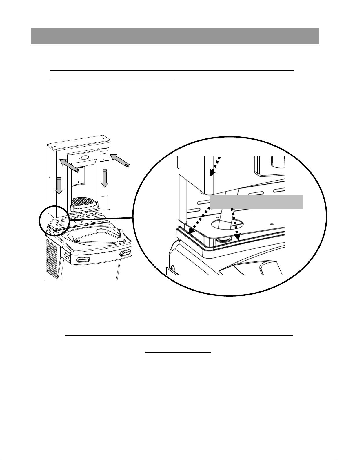
9. MAKE SURE the cabinet fits into the groove in the rubber gasket on
both sides and front of the wrapper.
Bottle
Filler
cabinet
Groove in the gasket
See next page to secure Bottle Filler assembly to frame
with torx screws.
19
Page 20
Section 3D: Installation
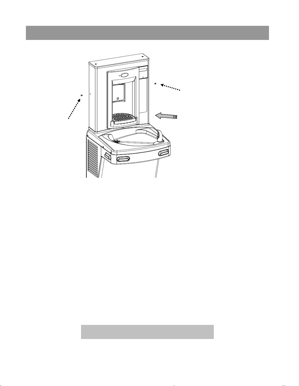
Torx screw
Torx screw
Insert bottle
10. Attach Bottle Filler assembly to the frame using two (2) torx screws.
Remove the Top Cap and two (2) torx screws used for mounting.
11. Plug bottle filler cord into the electrical outlet. The bottle filler will
auto-calibrate and be set up specifically for that installation. Refer to
the program guide on next page for further programming. Access
programing Pushbutton through top of Bottle Filler.
12. Turn ON water supply and check for leaks. Place a container in the
alcove to release any trapped air from the system.
13. If everything works correctly, place the Top Cap back on the Bottle
Filler and the two (2) torx screws to fasten it in place. Otherwise,
calibrate the sensor per the instructions on the next page.
INSTALLATION COMPLETE
20
Page 21
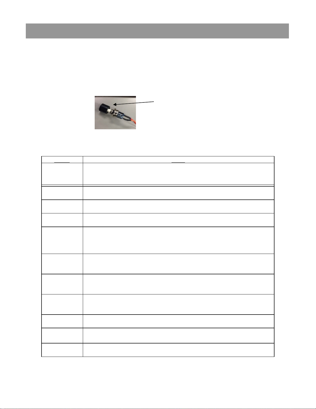
Section 4: Set-up guide for bottle filler electronics
GAL
or momentary press to advance to next menu.
UNFILT UNIT
or momentary press to advance to next menu.
RATE SELECTED
or momentary press to advance to next menu. Not included on all models.
Hold button 3 seconds to advance to the next menu.
[LTR COUNT]
[4731 LTR]
Or momentary press to advance to next menu.
(The 3 Sec rule increases the bottle count based on a 3 second dispense.)
BOT COUNT?
or momentary press to advance to next menu.
AGAIN?
or momentary press to advance to next menu.
Factory default program settings are:
• Units - Gallons
• Unfiltered unit
• Flow Meter = Rate Selected
• Filter Capacity = 1250 gallons [4731 liters] for a VersaFilter
Pushbutton
To change the program settings, follow these steps:
Display Action
000000000
BOTTLES REUSED
(Home Screen)
LTR/GAL
UNFILT/FILT?
Depress button for 3 seconds to enter into the following menu settings and make changes.
Note: at anytime it will exit menu and save settings when idle for 10 seconds (no button
press) and revert back to Home Screen.
Depress button 3 seconds to change from Gallons to Liters,
Depress button 3 seconds to change from Unfiltered to Filtered unit,
• Bottle Count = 0.5L (1 Bottle)
• Flow Rate = 1.2 GPM
• 20 second maximum dispense time
FLOW METER?
SELECT RATE
1.2 GPM UNIT
RESET 00000000
GALLON CNT
FILT CAPAC
OF 1250 GAL
3 sec rule?
0.5L
Reset 00000000
Bot Filler
Set_time: 20 s
RUN CAL
Depress button 3 seconds to change from Rate Selected to (Flow) Meter Enabled,
To change flow rate, momentarily depress button to change whole gallon digit.
Hold button 3 seconds to advance to TENTHS of gallon digit.
Depress momentarily to change the digit.
Depress button for 3 seconds to reset Gallon or Liter count,
or momentary press to advance to next menu.
Depress button for 3 seconds to change filter capacity to 3000 GAL [11355 liters] for
Versafilter II or Galaxi green filter.
Depress button for 3 seconds to switch from 0.5L bottle to 3 sec rule,
or momentary press to advance to next menu.
Depress button for 3 seconds to reset (Home Screen) BOTTLES REUSED count,
Depress button for 3 seconds to change maximum dispense time to 10, 20 or 30 seconds,
or momentary press to advance to next menu.
Depress button 3 seconds to run calibration again,
•
21
Page 22
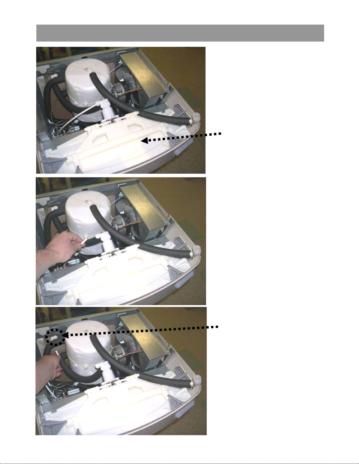
Addendum Section: Pressurizing Cooling Tank
The water should
already be turned OFF
and the power
disconnected.
Unit as it appears with
top removed
STEP 1
Unplug un-insulated water
line from water valve inlet
(quick-connect elbow
located left side of water
valve facing the front of
the cooler). Set tubing
aside (careful to not
contaminate water contact
end).
STEP 2
Unplug tubing from
quick-connect elbow
leading to cooling tank
inlet.
22
Page 23
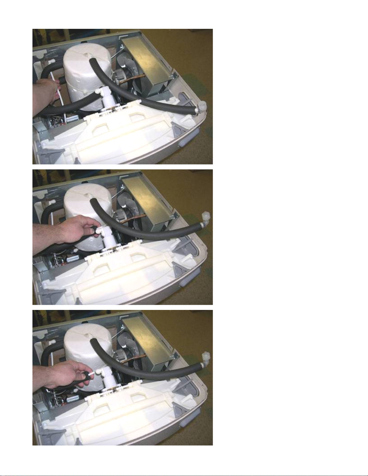
STEP 3
Plug un-insulated tubing
that was removed in step 1
into quick-connect elbow
leading to the cooling tank
from step 2.
STEP 4
Unplug tubing that is
connected to the water
valve outlet (quickconnect elbow located
on the right side of valve
facing the cooler).
STEP 5
Connect tubing from
step 4 to quick-connect
elbow on the left side of
the valve.
23
Page 24
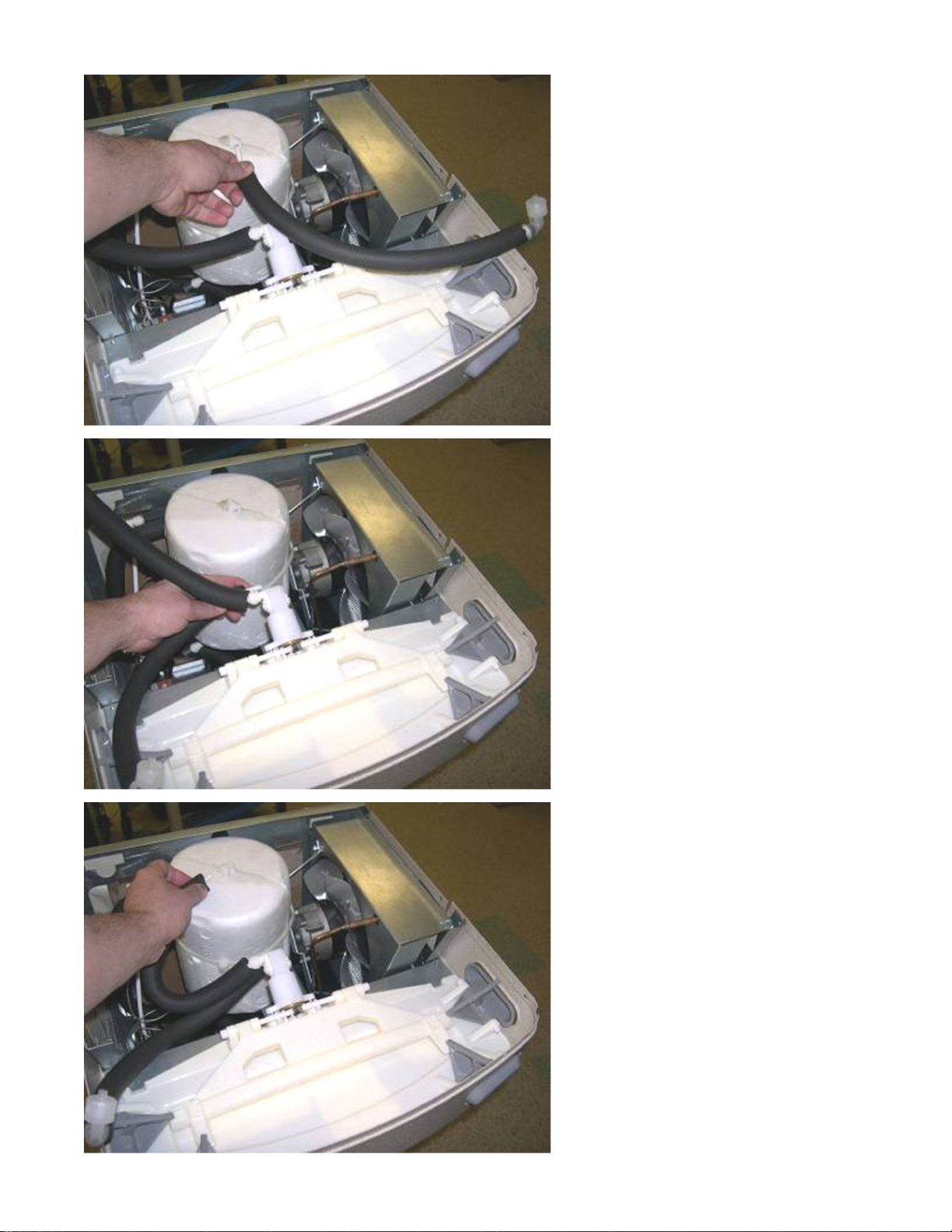
Step 6
Unplug quick-connect
tubing from the
cooling tank outlet.
Do not set it down.
Step 7
Using tubing removed
in step 6, plug into
quick-connect elbow
on the right side of the
valve. (be sure to route
the tubing under
existing tubing
installed in step 4 as
shown)
Step 8
Using tubing that is
connected to the
quick-connect elbow
left side of valve (done
in step 4), and plug the
other end into the
quick-connect fitting at
the top of the cooling
tank.
Return to Section 3 B
“Connecting the water line”
24
Page 25
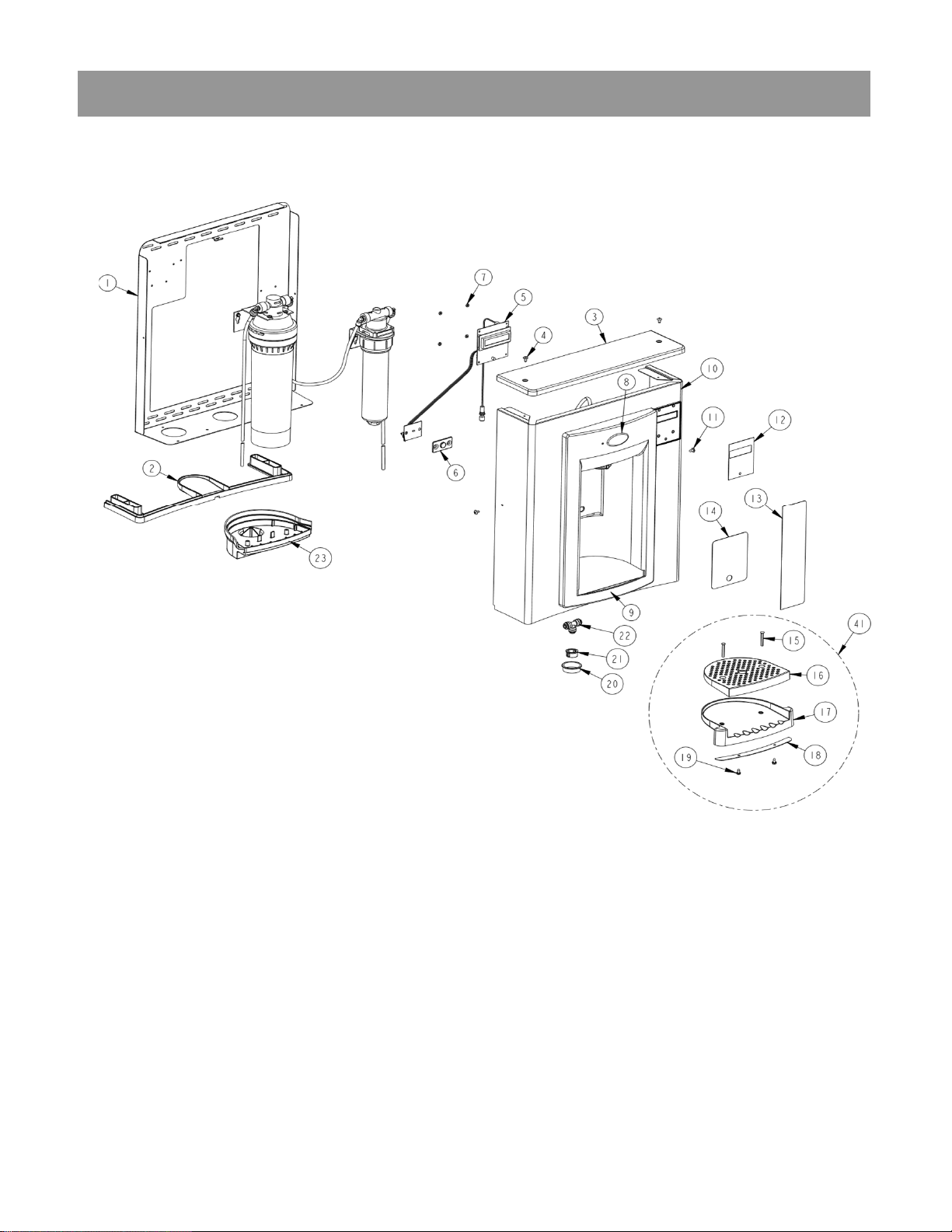
Section 5: Parts Breakdown
25
Page 26
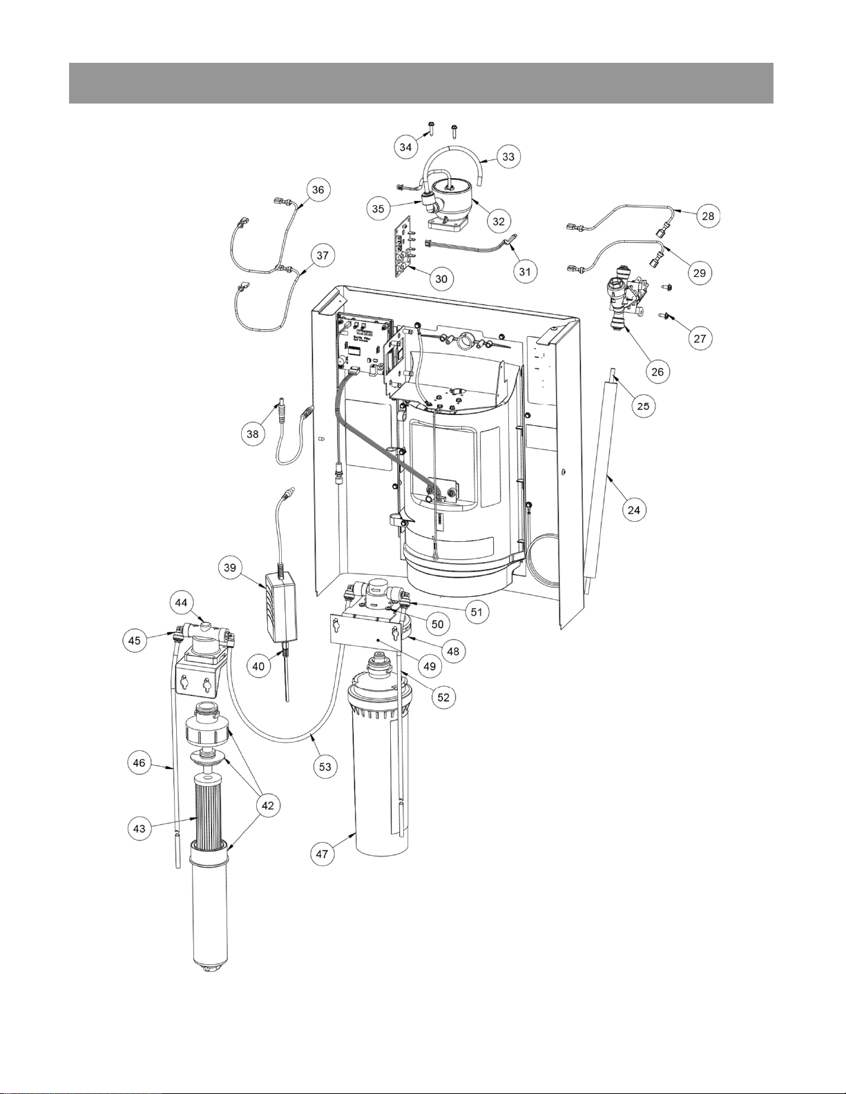
Section 5: Parts Breakdown
26
Page 27
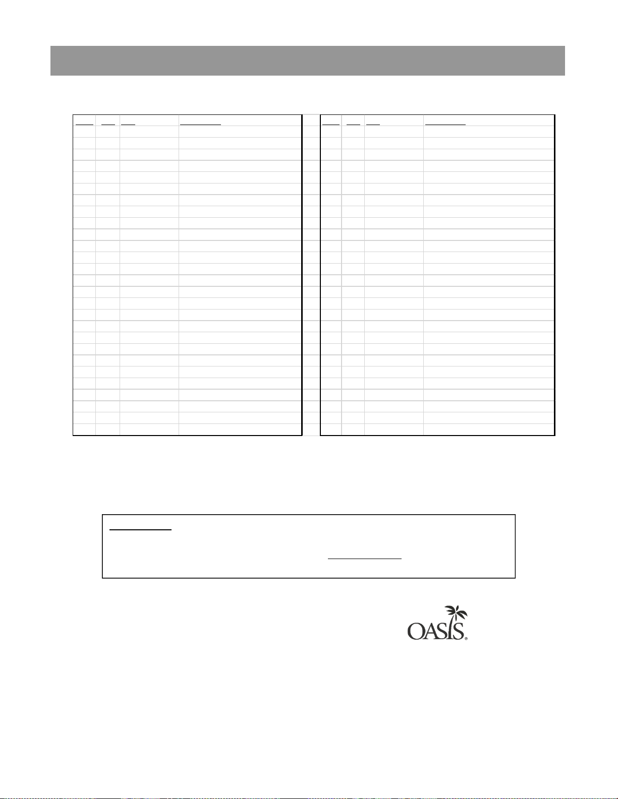
Section 5: Parts Breakdown continued
037059-001
037406-101
040707P001
029994-103
030152-158
041071-001
041072-001
041073-001
026630-022
029994-103
030152-046-SP
030152-157
ITEM QTY P/N Description ITEM QTY P/N Description
1 1 036687-003 FRAME, PWFSBF-K12 28 1 017340-483 LEAD WIRE ASSY BLACK 14"
2 1 036689-001 GASKET, PWSBF 29 1 021929-177 LEAD WIRE ASSY RED 14"
3 1 036686-001 CAP, PWSBF 30 1 041051-001 PCB, UV
4 2 031875-003 SCREW, TRUSS HD TAPPING TORX 31 1 041061-001 CABLE ASSY, 3 WIRE UV LED
5 1 038026-002 ELECTRONICS ASSY, IR/LCD 32 1 041050-002 UVC LED 9C+VISIBLE POD MODULE
6 1 038027-001 LENS, IR BOTTLE FILLER 33 1 030152-009 TUBE, PE WHITE 7.5"
7 4 026824-026 NUT, HEX NYLON 34 2 026642-016 SCREW, HEX HD TAPPING
8 1 031434-014 NAMEPLATE, OASIS 35 1 029962-103 FTG, PP REDUCING ELBOW
9 1 036190-005 ALCOVE, EBF UV LED 36 1 017340-483 LEAD WIRE ASSY BLACK 14"
10 1 036691-007 WRAPPER, PWEBF STN2 37 1 021929-177 LEAD WIRE ASSY RED 14"
11 2 031875-003 SCREW, TRUSS HD TAPPING TORX 38 1 041052-001 POWER ADPTR CABLE,18GA DC
12 1 038031-005 LABEL, LCD BEZEL 39 1 038036-003 POWER SUPPLY,100-240VAC/12VDC
13 1 038031-011 LABEL, PANEL QUASAR 40 1 038168-001 CORD ASSY, DC POWER SUPPLY
14 1 038031-006 LABEL, ALCOVE SENSOR 41 1 036701-001 DRIP TRAY ASSEMBLY
15 2 036049-002 SCREW, OVAL HD PLASTITE 42 1
16 1 036695-001 TRAY, GRILLE DRIP 43 1
17 1 036688-001 TRAY, DRIP PWSBF 44 1
18 1 036697-001 CAP, DRIP TRAY BOTTOM 45 1
19 2 026642-023 SCREW, HEX HD TAPPING #8 46 1
20 1 027189-001 BUSHING, SNAP 47 1
21 1 027189-008 BUSHING, SNAP 48 1
22 1 029199-103 FTG, PP UNION TEE WHITE 49 1
23 1 036191-002 DRAIN, MSBF, SHORT 50 4
24 1 017681-008-SP INSULATION, SPONGE TUBE 19" 51 2
25 1 030152-046-SP TUBE, PE WHITE 38" 52 1
26 2 038030-002 SOLENOID VALVE 12VDC 53 1
27 1 026642-023 SCREW, HEX HD TAPPING
FILTER HSNG ASSY, 1/4 TRN, SM
FILTER, REMEDI PAC
KIT, FILTER HEAD
FTG, PP ELBOW, PLUG IN
TUBE, PE WHITE 52.0"
FILTER CARTRIDGE, VERSAFILTER II
FILTER HEAD, VERSAFILTER II
BRKT, VERSAFILTER II
SCREW, PAN HD TAPPING
FTG, PP ELBOW, PLUG IN
TUBE, PE WHITE 38.0"
TUBE, PE WHITE 21.0"
P/N 030099-601, REV. A Date: 04/2020
© 2020 LVD Acquisition, LLC
Oasis and Versacooler are registered trademarks of LVD Acquisition, LLC dba
Oasis International.
Haws is a registered trademark of HAWS Corporation.
Elkay and Halsey Taylor are registered trademarks owned or licensed by Elkay
Sales Inc. and/or its parent Elkay Manufacturing Company
Accessories:
Vandal resistant screw kit: P/N 036704-001, includes torx bits and replacement screws.
Gasket, Sunroc/Haws : P/N 036689-101: (replaces item 2) KIT P/N 036752-001
Gasket Adapter, Elkay/Halsey Taylor P/N 041114-001
OASIS INTERNATIONAL
222 East Campus View Blvd.
Columbus, OH 43235
614-861-1350
www.oasiscoolers.com
27
 Loading...