

Oasis Landscaper 12, Landscaper 16 Installation And Operation Manual

CONTROLS
Installation
and
Operating
Manual
Please
read these instructions carefirlly
to obtain maximum benefit of this controller.
il
:r-----1-
ll
lt-. . _
h"-mll
li@l
h,aiJl
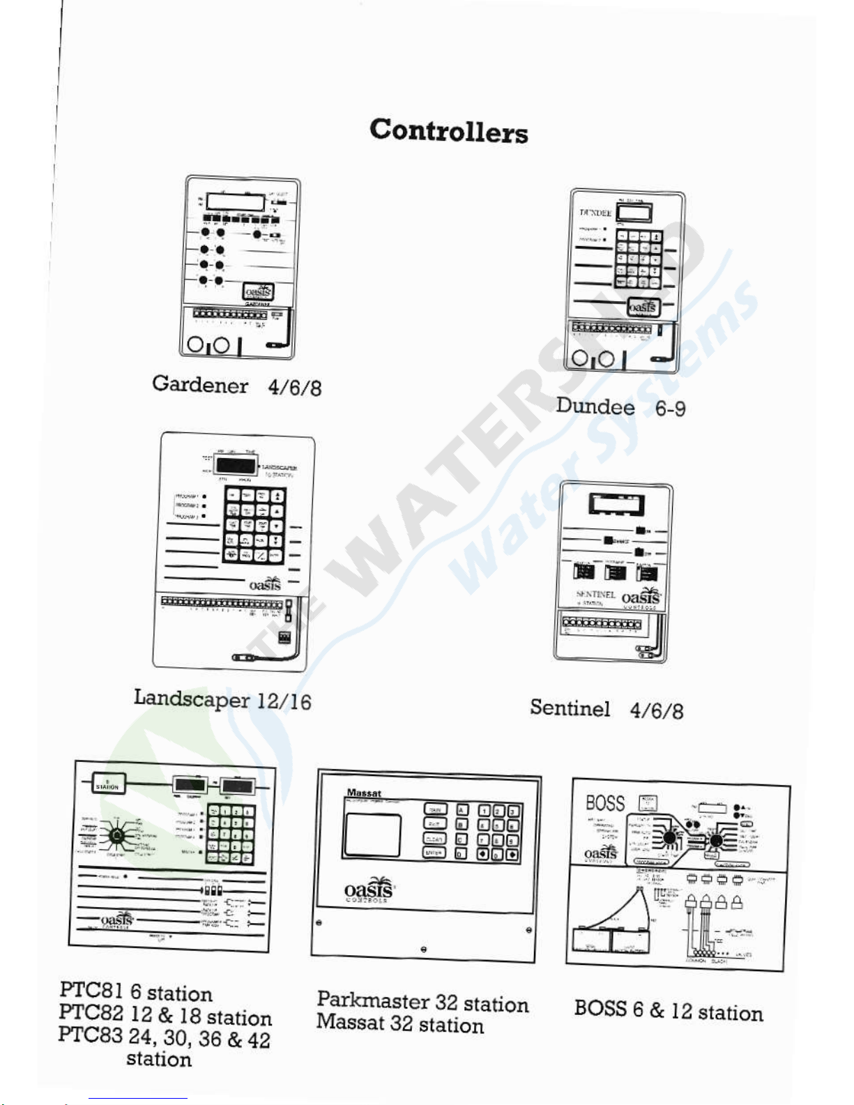
Gardener
4,/6,/g
Landscaper
1Zl6
Gontrollers
Parkmaster
32 station
Massat
32
station
Durdee
6-9
Sentinel
4/6,/8
PfC8l
6
stalion
PIC82
12
&
l8 station
PTC83
24,
30,
36
& 42
station
B0ss
#.'m
BOSS6&l2slarion
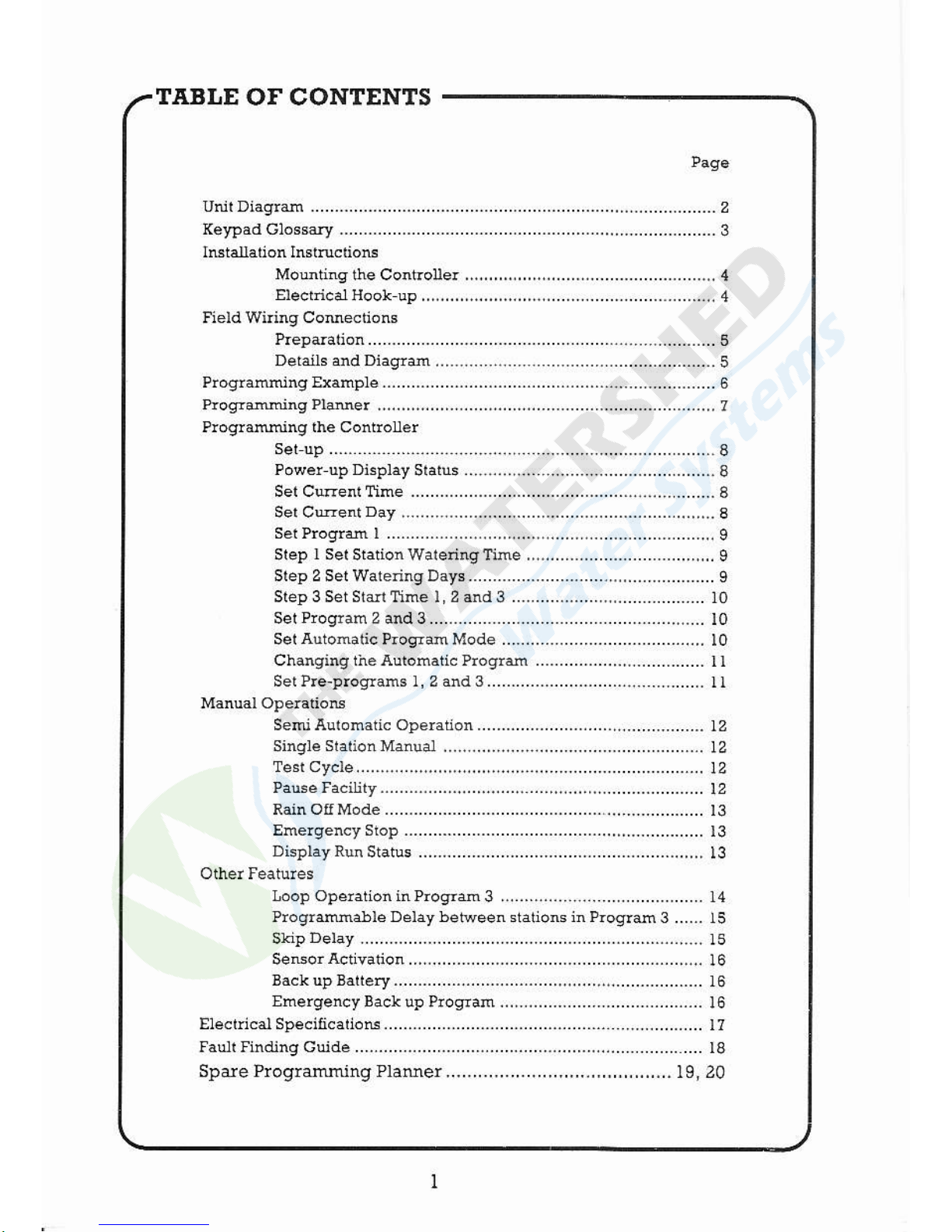
TABI,E
Of CONTENTS
Unil Diagrffi ............-..............-.......-.............-.............,,,................-.
2
(e}?adGlossary.............-......--.............................-...,,...........--.....-..3
IBtarhtion Inshcliom
Moutinq$eControUe!,,.,,,,,,..,,,,..,,,...-.,...............-......-...4
Eleclrica1Hoo1up,,,.,,,,,,..,,,,,...,,,,..,......................__......_...4
Field Wiring Comectiong
Prepdation...........................-.....-......................................5
Details and Diaqya..........................................._......_.....,
5
PlogrammingExample.-.............-.......-.............................................6
Progrming PlNer
...,,,,...,,.,,........,.,,....,,....-........-...............-....,,,
7
Progrming lhe ControUer
set up ............. ...........
.. .,.......,........................-................
I
PowerupDisp]ayS1aius..,.....,,,.......................................-.8
Set Crenl Tim€ ..............-.............-................,........
......-. I
Ser Crenl
Day
,...................... ......-.......-.......-.............,,...
a
SeiProgr 1 .......................,,,....,,...,.....................-..........9
Slep
I Sel
StationWalerinqfifre,,.,,,...-.................-....,,...,,
I
Step 2 Sel WarennqDa]T......-..............-.......,..,..................
I
Step 3 Set SIan Time l,2 and
3
...-..............,..,,.................
10
SetProqtan2and3..................-................-........-.....,......
l0
Sel
Automatic
PrcgramMode,....,....-...............--............,,
l0
Changing iheAutomatic Progrd ..-.............,.,.........-......
I I
Sel Pre-prooams l, 2 dd 3......................................-......
]l
SemiAulomaticOperation....................-.......,................-.12
Single
SIalioiMatual,.,,....,,,,....,,..,.................................
l2
TesiCycle.....,......,....,,,...,,,,,,....,,..,.,...........-........-......-....
l2
PalseFaciuly-.....--......,.....,,,,,.......-......-.....12
Rain OIfMode.....-...............
Emelgencystop...............-...........................,,,--.......-......
13
Display Run
Status ....-.....................-................-........-..,,,,
l3
Ioop Operation inProgle
3,...........,...................._........ 14
Progrffiable Delay bet'reen stalions h ProqTm
3 ...... l5
SkipDetay..............-......-.............-................-.............,....
15
SeEorActivaioa..,....,...-............................................,....
16
BackupBattery.....-.......-......-............,,.......,,........-...........
16
Ehergency
Bac! up Plogram,,,,..,......................-............
l6
Ele.dcalSpecificatioG.............-.......-............--...........
.................. l7
la!llfjndingGuide...........-......-.....................-.......-...,..................
18
Spde Progrming Plamer..........................................
t9, 20

;fift.^
OASIS
CONTROLS
PFOGRAM
OPEMTING
INDICATOB
LIGHTS
DIGITAL
D]SPLAY
KEYPAD
PROGRAI,IMING
STATION
OUTPUT
CONNECTONS
N,4ASTER VALVE/
PUI,IP
START
CONNECTION
C0l\41\4ON
TEFI,4INAL
CONNECT]ON
FUSE
24V AC
INPUT
OPTION
SW]TCH
BACK.UP
BATTERY
PFESSUFE
I4OISTUFE
SKIP
SENSOR
SENSOR
INPUT
INPUT
I.ANDSCAPER
CONTROLI,ER
CONNECTOR
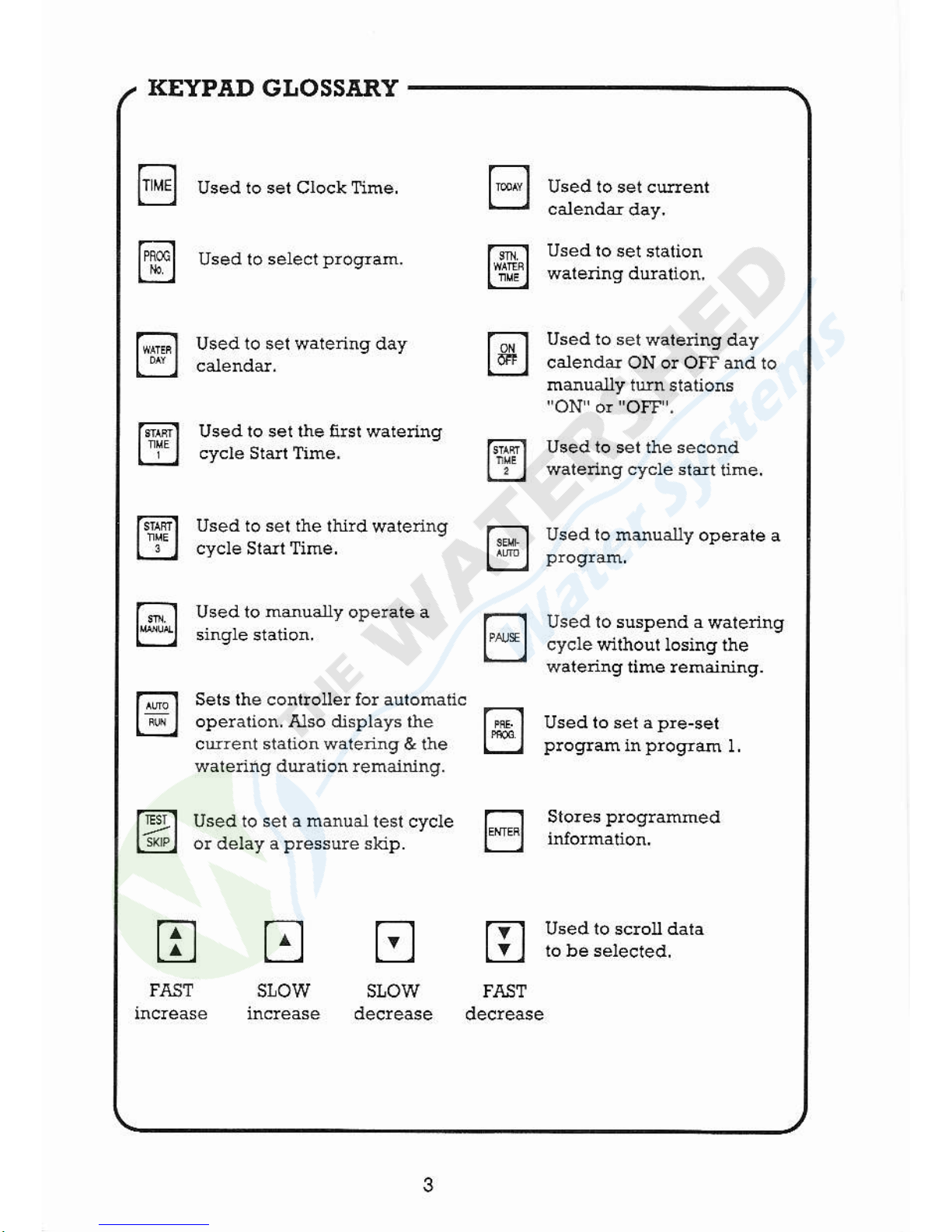
KEYPAD GI,OSSARY
Used to set Clock Time.
Used 1o select
progllam.
Used to sel walering day
Usedto set the tusl wateling
Used io
set wateling day
calendar ON o! OFF
ard to
manually
turn slations
"ON'
or
"OFF
.
Used lo set the second
wateling cycle siart
time,
tr
sl,ow
G;Fl Used to ser the rlurd watennd
l"iJl ;;;.:."),;;:
" """-
"
r.o_l
used ro msuaxy ope€'e
a
L:jl
ptosrM
Used to
m@ually
opelate a
Sets the controller for autohalic
operation. Also displays the
curent slalion waiedng & the
wateling duation remainirg.
sf,ow FAsr
decrease decrease
Used lo suspend a
walering
cycle wilhoul losing
the
watenng tihe remairing.
Used to sel a
pre-set
Progre
in
progfas
1
Stoles
proglammed
fEil Used to ser a manuar resr cvcle f--
L-wpl
oraeuv a
pressue
srcp.
fll
FAST
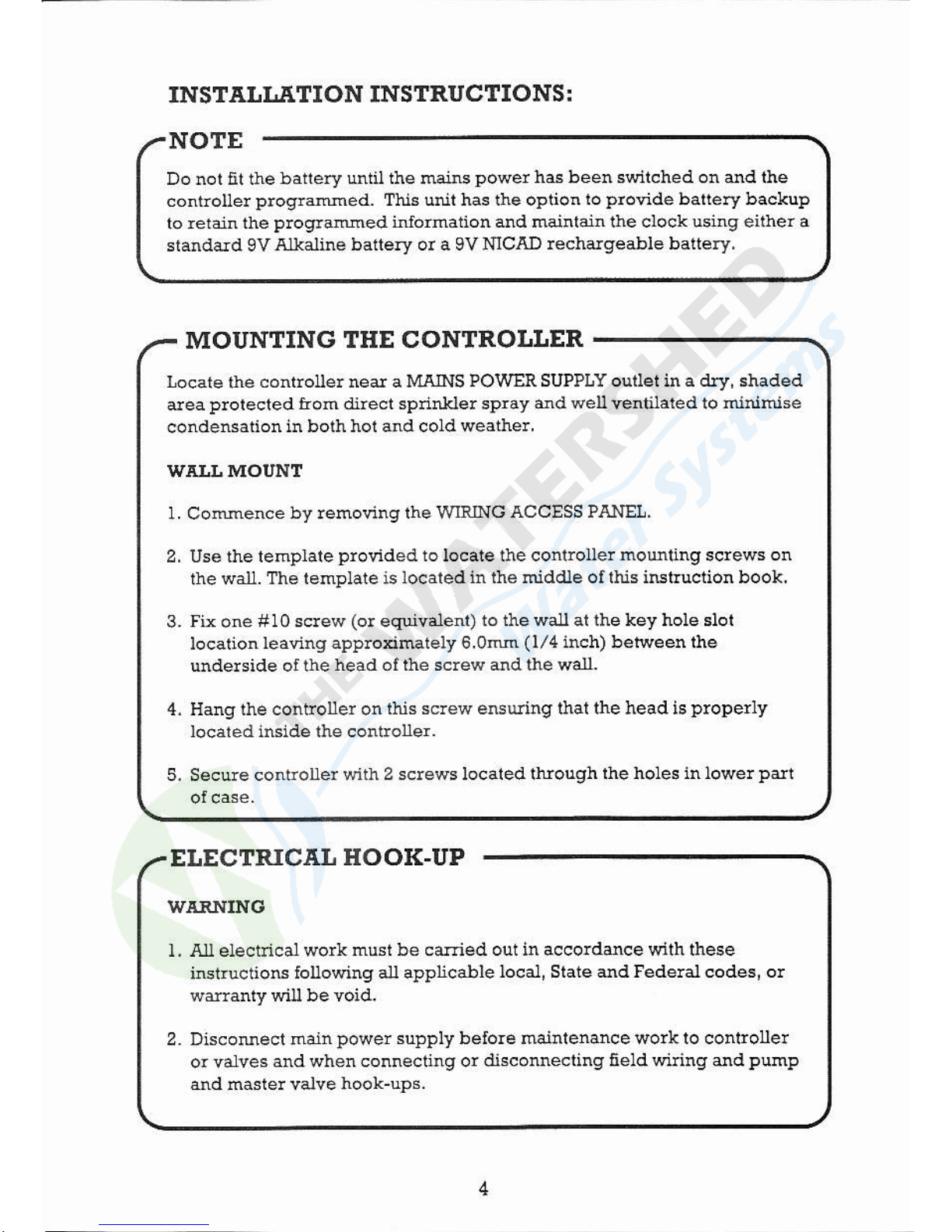
Do not fit the battery
util the mains
power
hs been sdtched on ed ihe
controUe!
plogGmed. This unit has the oplion
lo
Provide
ballely backuP
10
retain the
plograMed inloimalion and saintain the clock using eithei a
slandard 9V
Alkaline battery or a 9V MCAD
rechargealle battery.
INSTAI,IJI,TION INSTRUCTIONSI
NOTE
MOUNTING THE CONTROLLER
ELECTRICAI
HOOK-UP
Locate
the
controller ned a MAINS
POWER SU?PLY ouilei in a dty, shaded
dea
prorected rrom direct spnnlder spray and
weu
vendlaled lo
minihise
condensation
in both hol andcoldweathe!.
W'AII MOI'NT
1 Comence
by removing the IVIRING
ACCESS PANEI.
2. Use the templale
pronded
to locate the contlolle!
mounting
screws on
rhe watl.
The template is localed
in lhe midaUe or lhis irBtruction book.
3.
Fix
one
# 10 sclew
(o!
equvalenl)
to the waU at the key hole slot
location
leaving apploximately 6.otu
(t/4
inch) between ihe
underside o! the
head
of
lhe screw and the wall.
4. tlang the controller on
ihis sclew ensuring thal the head is
ptoperly
locared inside the conilol]er.
5. Secule contiolle!
sith 2 sclews localed through
lhe holes in lowe!
Pdt
WI.RNING
l. .q.U electrical work
musi be caEied out in accoldance wlth these
instoctioc
louowing all applicable
local, Siate dd Fedelal
codes,
o!
wdlanry wiu be votd.
2. DiscoMect m.rn
power
supply belore mainlenance work to conlrouer
or valves
and when connecling or drsconnecting
field wiling ed
PumP
and masle! valve hook-ups.
I Prepare wtes
fo! hook-up by slripping
apploximately 6.0mn
(l/4
inch)
of
lnsulation Aom end to be comeded
to lhe controller.
2.
EEEe
ielminal block sclews
de loosened enough to
Permit
easy
acces
IIELD WIRING CONNECTIONS
:
PREPAR.6.TION
DETAILS AND DIT.GR.trM WITH
PUMP HOOI(-UP
3. CoMect wires lo lerminai
block by
pushinq
stnpped end of wlre
into
ciamp apeltue
md
lighlen
sclews, Do not over
righten as
this
may
ddage
lhe lerminal biock.
4. A maximum
of 0.5 amps 24V AC
(50/60
Hz) may be coMecled lo each
5. EEEe ttEt
fie1d winng icialled at time ol
onginal istallation bui noi
intended for imedrate
Ee is NOT CONNEC1ED 10 the coniroue!.
Unused
wires connected to the conirolle!
act as an aenal io! Ughlnirg
ed cdnleacl lo conrroller damage
by inducdon.
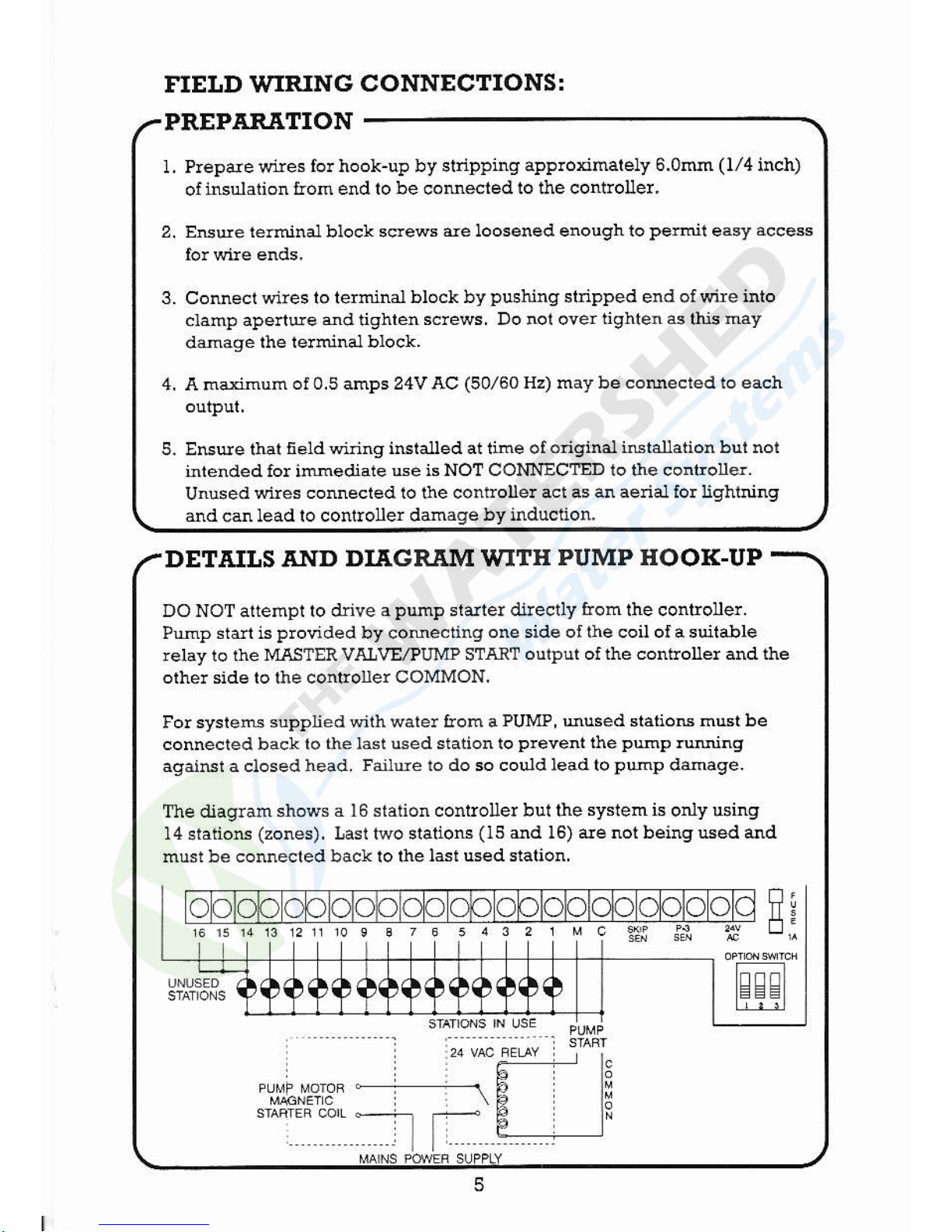
DO NOT altempl 10 drive
a
php
staiter di.recdy
from
lhe conlroue!.
Prnp stdt is
plovided
by comecling
one side oI the coil ol a 6uitane
relay
ro
rhe MASTER VI$VE,?uMP 5TAR1
output of the contloller and the
orhe! side to lhe conEolerCOMMON.
Fo! sysleru supplied
with wale! floh a
PUMP, Mused
statiotu
hust be
connecred back 1o
the last used station to
plevent
the
PlhP
rNing
agaiNr a ctosedhead.
Failue lo do so couldleadtopEp ddnage.
Tle diagram shows
a 16 siation conlroller bul the
system is
only usirg
14
sraiiotr
(zones).
Lasl two stalions
(15
dd 16) are not beingused ard
must be connected bdcv lo rhe
lasl usedslalion.
olc
FE:
 Loading...