

Oasis C8b, H17b, C25b, C25Tb, C35T-Vb Installation Instructions Manual
...
SWIMMING POOL HEAT PUMP UNIT
Installation & Instruction Manual


CONTENTS
1. Preface
2. Specifications
2.1 Performance Data of Swimming Pool Heat Pump Unit
2.2 Dimensions for Swimming Pool Heat Pump Unit
3. Installation and Connection
3.1 Installation of System
3.2
3.3 How Close to You r P oo l?
3.4
3.5
3.6 Initial Start-up of the Unit
4. Usage and Operation
4.1
4.2
4.3
5. Maintenance and Inspection
5.1
5.2 Malfunction table
6.Appendix
Spa Heat Pumps Location
Spa Heat Pumps Plumbing
Spa Heat Pumps Electrical Wiring
Function of wire controller
The controller usage
Parameter table
Maintenance
6.4 Cable specification
6.1 Connection of PCB Illustration
6.2 Connections Explanation
6.3 Caution & Warning
6.5 Explosive view of the unit
1
2
2
4
6
6
7
7
8
9
9
10
10
12
19
20
20
21
22
22
22
23
24
25

1. PREFACE
The unit can only be repaired by qualified installer center personnel or an authorised
dealer.
Maintenance and operation must be carried out according to the recommended time and
frequency, as stated in this manual.
Use genuine standard spare parts only. Failure to comply with these recommendations
will invalidate the warranty.
SWIMMING POOL HEAT PUMP Unit heats the spa water and keeps the temperature
constant.
This type of pump has the fol lowing cha ra cteristic s:
1. Durable
Withstand prolonged exposure to corrosives such as chlorine. The heat exchanger is
made of pvc & titanium tube which can .
2. Install at ion flexib ility
The unit can be installed outside or inside of the Spa.
3. Quiet oper at ion
The unit comprises an efficient rotary/ scroll compressor and a low-noise fan motor,
which guarantees its quiet operation.
4. Advanced c on trolling
The unit includes micro-computer controlling, allowing all operation parameters to be set.
Operation status can be displayed on the wire controller.
1
In order to provide our customers with quality, reliability and versatility, this
product has been made to strict production standards. This manual
includes all the necessary information about installation, debugging,
discharging and maintenance. Please read this manual carefully before
you open or maintain the unit. The manufacturer of this product will not be
held responsible if someone is injured or the unit is damaged, as a result of
improper installation, debugging, or unnecessary maintenance. It is vital
that the instructions within this manual are adhered to at all times. The unit
must be installed by qualified personnel.
2
2.SPECIFICATION
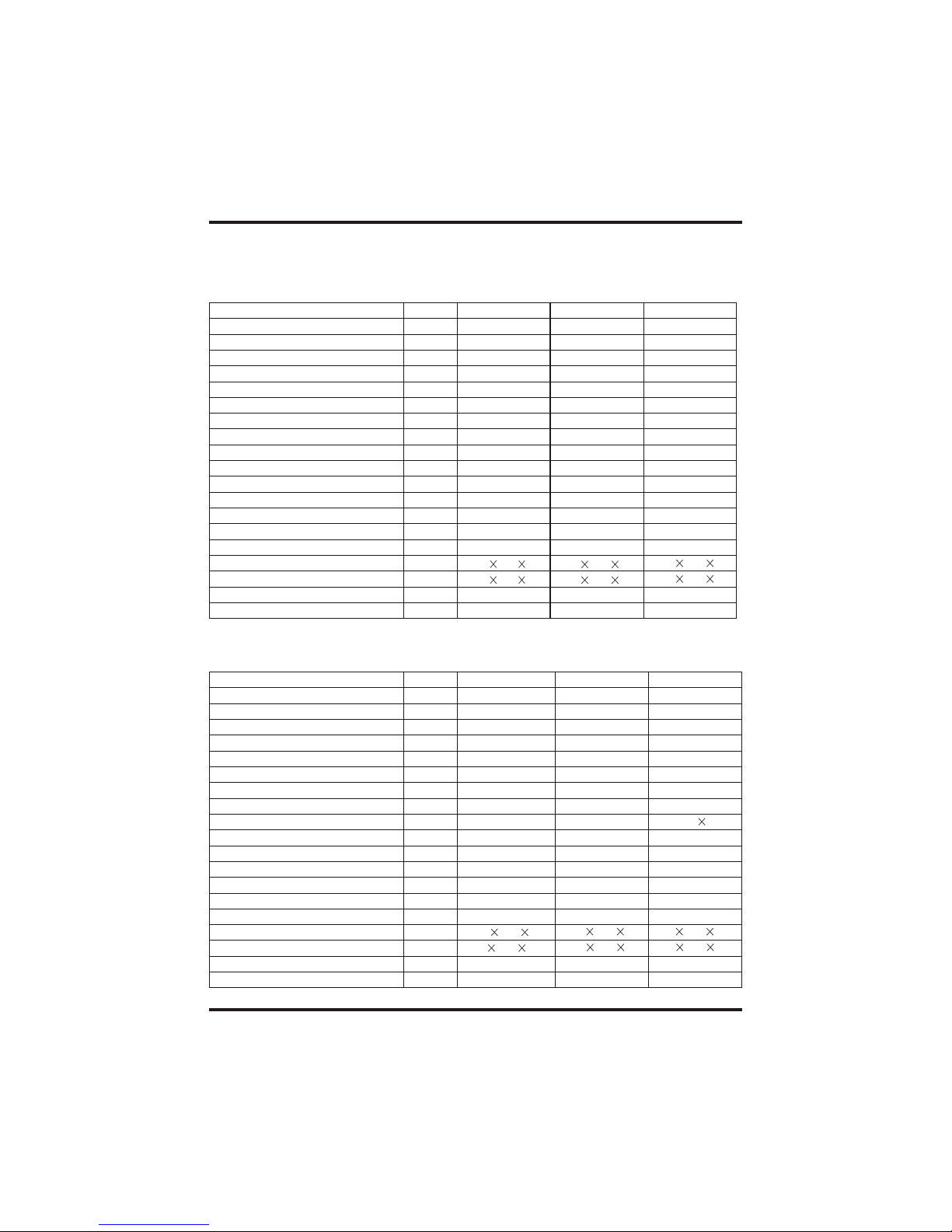
2.1 Performance data of Swimming Pool Heat Pump Unit
REFRIGERANT :R407C
Unit
Heating Capacity
Heating Power Input
Running Current
Power Supply
Compressor Quantity
Compressor
Fan Quantity
Fan Power Input
Fan Rotate Speed
Fan Direction
Noise
Water Conne ction
Water Flow Volume
Wat er Pres sure Dr op(ma x)
Unit Net Dimensions(L/W/H)
Unit Shipping Dimensions(L/W/H)
Net Weight
Shipping Weight
Model
kW
BTU/h
kW
A
W
RPM
dB(A)
inch
3
m/h
kPa
mm
mm
kg
kg
Oasis C13b
13.2
45000
2.6
11.8
230V~/50Hz
1
Rotary
1
120
850
Horizontal
54
1.5
4.5
10
1000 420 650
1060 440 710
65
72
REFRIGERANT :R407C
Unit
Heating Capacity
Heating Power Input
Running Current
Power Supply
Compressor Quantity
Compressor
Fan Quantity
Fan Power Input
Fan Rotate Speed
Fan Direction
Noise
Water Conne ction
Water Flow Volume
Wat er Pres sure Dr op(ma x)
Unit Net Dimensions(L/W/H)
Unit Shipping Dimensions(L/W/H)
Net Weight
Shipping Weight
Model
kW
BTU/h
kW
A
W
RPM
dB(A)
inch
3
m/h
kPa
mm
mm
kg
kg
Oasis C17b
17.5
60000
3.5
15.9
230V~/50Hz
1
Scroll
1
120
850
Horizontal
54
1.5
6.0
10
1120
470 850
1200
480 1010
100
108
Oasis C8b
8.8
30000
1.7
7.7
230V~/50Hz
1
rotary
1
120
850
horizontal
51
1.5
3.0
10
1000 420 650
1060 440 710
60
67
Oasis H13b
13.2
45000
2.6
11.8
230V~/50Hz
1
Rotary
1
120
850
Horizontal
54
1.5
4.5
10
1000 420 650
1060 440 710
65
72
Oasis H17b
17.5
60000
3.5
15.9
230V~/50Hz
1
Scroll
1
120
850
Horizontal
54
1.5
6.0
10
1120
470 850
1200
480 970
100
108
Oasis C25b
25
90000
5.0
22.7
230V~/50Hz
1
Scroll
2
120 2
850
Horizontal
56
1.5
9.0
12
1120
470 1240
1200
490 1380
132
145
3
2.SPECIFICATION
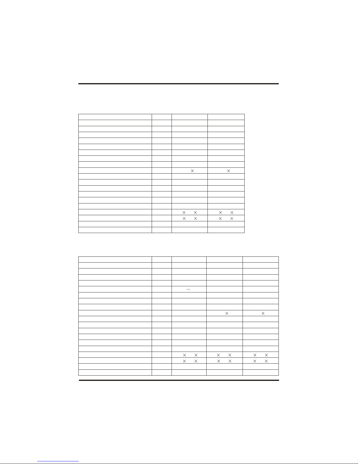
2.1 Performance data of Swimming Pool Heat Pump Unit
REFRIGERANT :R407C
Unit
Heating Capacity
Heating Power Input
Running Current
Power Supply
Compressor Quantity
Compressor
Fan Quantity
Fan Power Input
Fan Rotate Speed
Fan Direction
Noise
Water Conne ction
Water Flow Volume
Water Press ure Drop(max)
Unit Net Dimensions(L/W/H)
Unit Shipping Dimensions(L/W/H)
Net Weight
Shipping Weight
Model
kW
BTU/h
kW
A
W
RPM
dB(A)
inch
3
m/h
kPa
mm
mm
kg
kg
Oasis C35T-Vb
35
120000
7.1
12.7
380V/3N~/50Hz
2
Scroll
2
200 2
850
Horizontal
61
2.0
12
15
1490 735 1130
1520 790 1340
244
284
Oasis C25Tb
25
90000
5.0
8.3
380V/3N~/50Hz
1
Scroll
2
120 2
850
Horizontal
56
1.5
9.0
12
1120
470 1240
1200
490 1380
130
140
REFRIGERANT :R410A
Unit
Heating Capacity
Heating Power Input
Running Current
Power Supply
Compressor Quantity
Compressor
Fan Quantity
Fan Power Input
Fan Rotate Speed
Fan Direction
Noise
Water Conne ction
Water Flow Volume
Water Press ure Drop(max)
Unit Net Dimensions(L/W/H)
Unit Shipping Dimensions(L/W/H)
Net Weight
Shipping Weight
Model
kW
BTU/h
kW
A
W
RPM
dB(A)
inch
3
m/h
kPa
mm
mm
kg
kg
Oasis C21b
22
75000
4.25
19.32
230V~/50Hz
1
Scroll
2
120 2
850
Horizontal
56
1.5
7.5
12
1120 470 1240
1200
490 1410
135
152
Oasis C50T-Vb
55
187000
11.6
20.7
380V/3N~/50Hz
2
Scroll
2
390 2
900
Horizontal
61
2.0
19.5
15
1490 735 1130
1520 790 1340
300
325
EH9b
9.2
31400
1.65
7.50
230V /50Hz
1
rotary
1
120
850
horizontal
51
1.5
3.0
10
1002 455 658
1130 470 695
61
71
4
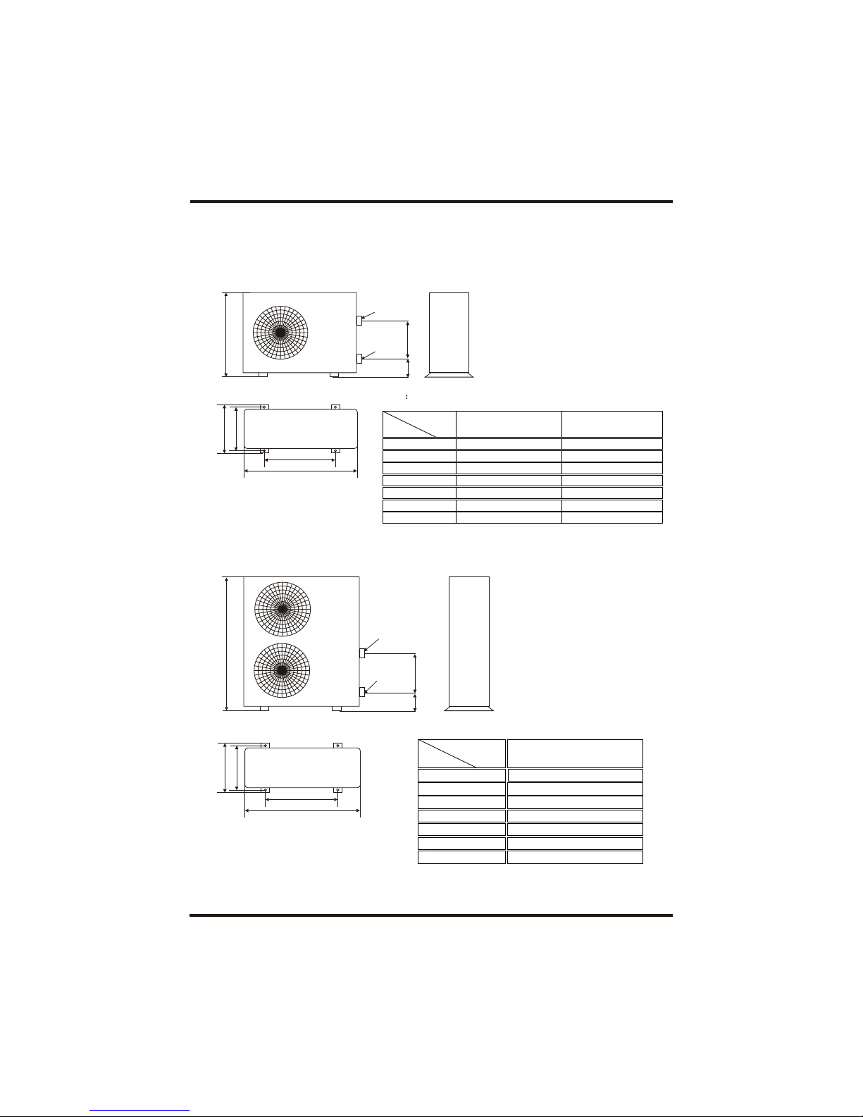
2.2 The dim ensions for Swi mming Pool He at Pump Unit
2.SPECIFICATION
Models: Oasis C8b/Oasis C13b/Oasis H13b/Oasis C17b/Oasis H17b
Models: Oasis C21b/Oasis C25b/Oasis C25Tb
Water In let
Water Ou tlet
A
E
D
C
B
TYPE
B
A
C
D
SIZE
E
unit mm
Oasis C8b/C13b/H13b
650
1000
700
420
400
255
101
Horizontal vision
Vert ical v ision
Oasis C17b/H17b
850
1120
720
470
440
400
97
TYPE
B
A
C
D
SIZE
1240
1120
720
470
440
475
95
E
Unit mm
Oasis C21b/C25b/C25Tb
A
E
D
C
B
Horizontal vision
Wat er In let
Water Outlet
Vertical visio n
FG
F
G
F
G
GF
5
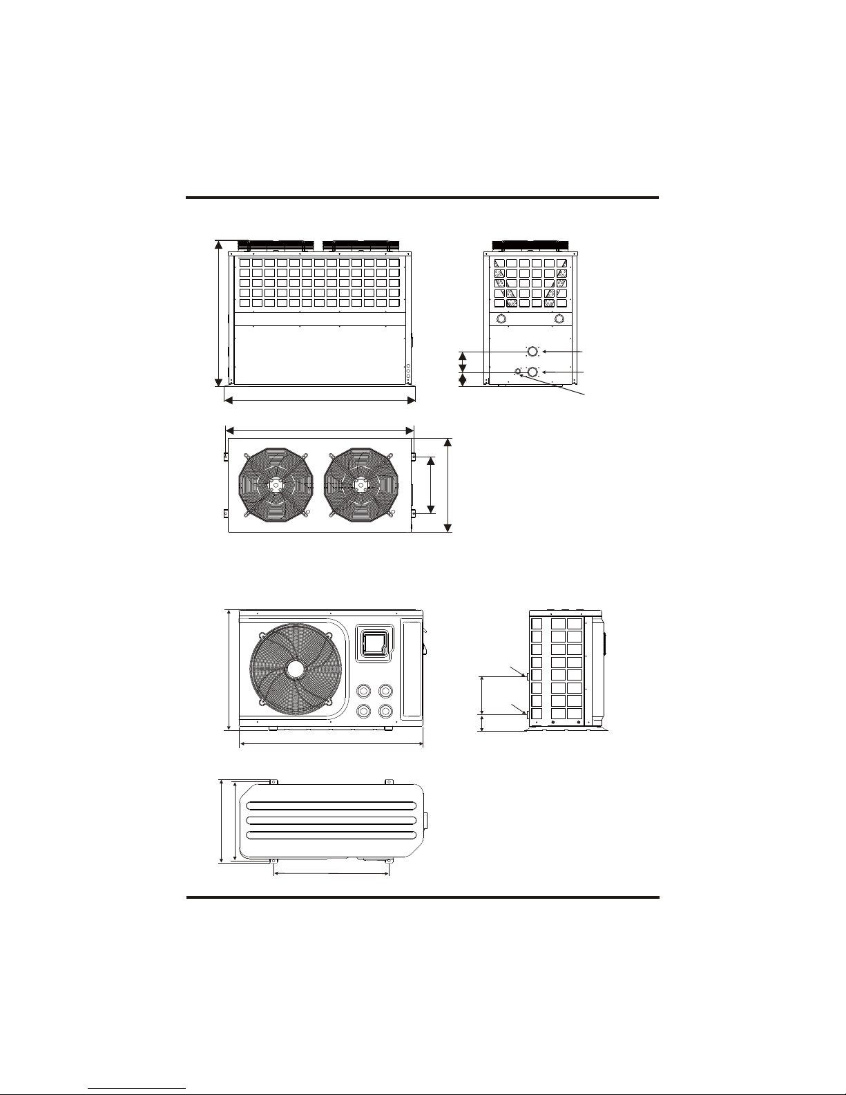
2.SPECIFICATION
Models:
Oasis C35T-Vb/Oasis C50T-Vb
Models:
EH9b
1002
658
430
455
630
Water In let
Water Ou tlet
Hor izont al visi on
Vertical vision
113 0
1490
1464
480
735
Water inlet
Water outlet
Drainage
Horizontal vision
Vertical vision
255102.5
88 120
6
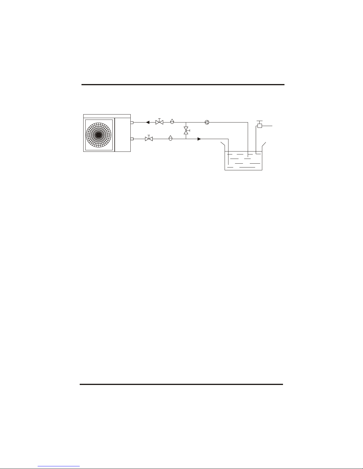
Installation items:
The factory only provides the heat pump unit; the other items in the illustration are
necessary spare parts for the water system ,provided by users or the installer.
3.1 Install at ion illustr ation
3.INSTALLATION AND CONNECTION
Chlorinator cell
Wat er outl et
Pool
Val ve
Wat er supp ly
Wat er inle t
Water pump
Sand fi lter
(or other type filter)
By-pass valve
Special Notes:
If the heat pump is used to heat the spa, then the parts will not strictly like what shown as
above, please make sure the water loop is clear and enough.
7
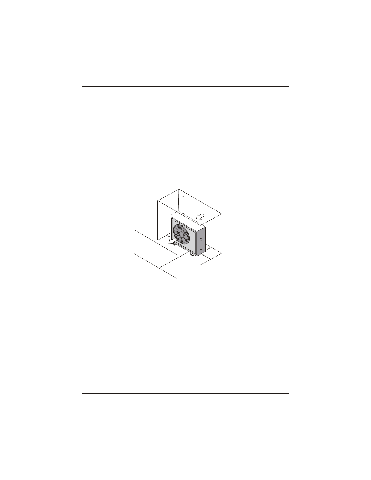
The uni t will pe rform well in an y outdo or loca tion pr ovide d that t he follo wing th ree fac tors ar e present .
1. Fresh Air - 2. El ectricity - 3. filter pipi ng
DO NOT place the unit in an enclosed area with a limited air volume, where the units
disch arge ai r wil l be re-c ircul ate d. DO NOT plac e the uni t to shrubs wh ich can b lock air inl et. These
locations deny the unit of a continuous source of fresh air which reduces it efficiency and
may prevent adequate heat delivery.
3.2 Spa Heat Pumps Location
3.3 How Close To Your spa?
3.INSTALLATION AND CONNECTION
Air inlet
Air outlet
2500mm
700mm
300mm
500mm
700mm
Norma lly, the longer th e distanc e from the spa, t he gre ater the h eat lo ss from th e pipi ng. I t
is rec ommen ded to ins tall t he hea t pu mp nea r the spa.
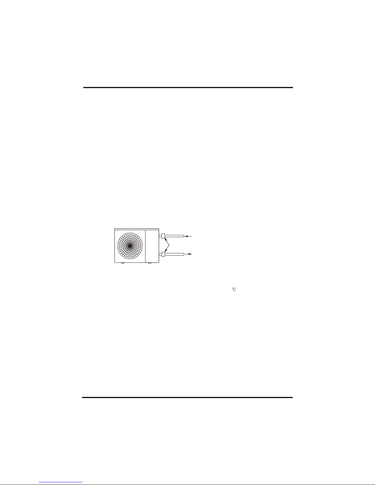
3.4 Spa Heat Pumps Plumbing
Locat ion: C onnec t the unit in the poo l pump disch arge (ret urn) l ine do wnstr eam o f all f ilter
and po ol pum ps, and up strea m of a ny chl orina tors, ozona tors or ch emica l pump s.
Stand ard mo del ha ve slip gl ue fit tings whi ch acc ept 40 mm NB PVC p ipe f or con necti on to
the po ol or spa f iltra tion p iping . By using a 50 NB to 40NB you ca n pl umb 50 NB PVC pip ing
strai ght in to the uni t.
Give s eriou s cons idera tion to ad ding a qui ck cou pler f ittin g at the un it inlet a nd out let t o allo w
easy d raini ng of unit for wi nteri zing and t o prov ide e asier acces s shou ld servic ing be
required.
Condensation: Since the Heat pump cools down the air about 4 -5 , water may condense on
the fins of the horseshoe shaped evaporator. If the relative humidity is very high, this could
be as much as several litres an hour. The water will run down the fins into the basepan and
drain out through the barbed plastic condensation drain fitting on the side of the basepan.
This fitting is designed to accept 3/4" clear vinyl tubing which can be pushed on by hand and
run to a suitable drain. It is easy to mistake the condensation for a water leak inside the unit.
NB: A quick way to verify that the water is condensation is to shut off the unit and keep the
pool pump running. If the water stops running out of the basepan, it is condensation. AN
EVEN QUICKER WAY IS to TEST THE DRAIN WATER FOR CHLORINE - if the is no chlorine
present, then it's condensation.
3.INSTALLATION AND CONNECTION
To Sp a
From pump
PVC COUPLER
RECOMMENDED(Provided)
The Spa Heat Pumps exclusive rated flow titanium heat exchanger requires no special
plumbing arrangements except bypass(please set the flow rate according to the nameplate).
The water pressure drop is less than 10kPa at max. Flow rate. Since there is no residual
heat or flame Temperatures, The unit does not need copper heat sink piping. PVC pipe can
be run straight into the unit.
8
Horizontal vision

9
3.5 Spa Heat Pu mps Electri ca l Wiring
NOTE: Although the unit heat exchanger is electrically isolated from the rest of the unit, it
simply prevents the flow of electricity to or from the pool water. Grounding the unit is still
required to protect you against short circuits inside the unit. Bonding is also required.
3.INSTALLATION AND CONNECTION
3.6 Initial startup of the Unit
NOTE- In order for the unit to heat the pool or spa, the filter pump must be running to
circulate water through the heat exchanger.
Start up Procedure - After installation is completed, you should follow these steps:
1. Turn on your filter pump. Check for water leaks and verify flow to and from the pool.
2. Turn on the electrical power supply to the unit, then press the key ON/OFF of wire
controller, It should start in several seconds.
3. After running a few minutes make sure the air leaving the top(side) of the unit is
cooler(Between 5-10 )
4. With the unit operating turn the filter pump off. The unit should also turn off automatically,
5. Allow the unit and pool pump to run 24 hours per day until desired pool water temperature
is reached. When the water-in temperature reach setting, The unit just
shuts off. The unit will now automatically restart (as long as your pool pump is running)when
the pool temperature drops more than 2 below set temperature.
Water Flow Switch - the unit is equipped with a flow switch that turns it on when the pool
pump is running and shuts it off when the pump shuts off. This switch is the same type used in
all gas pool heaters and is factory adjusted for normal pool installations. If the pool water
level is more than a few feet above or below the thermostat knob of the unit, your dealer may
need to adjust it at initial startup.
Time Delay- The unit is equipped with a 3 minute built-in solid state restart delay included to
protect control circuit components and to eliminate restart cycling and contactor chatter.
This time delay will automatically restart the unit approximately 3 minutes after each control
circuit interruption. Even a brief power interruption will activate the solid state 3 minute
restart delay and prevent the unit from starting until the 5 minute countdown is completed.
The unit has a separate molded-in junction box with a standard electrical conduit nipple
already in place. Just remove the screws and the front panel, feed your supply lines in
through the conduit nipple and wire-nut the electric supply wires to the three connections
already in the junction box (four connections if three phase). To complete electrical hookup,
connect Heat Pump by electrical conduit, UF cable or other suitable means as specified (as
permitted by local electrical authorities) to a dedicated AC power supply branch circuit
equipped with the proper circuit breaker, disconnect or time delay fuse protection.
Disconnect - A disconnect means (circuit breaker , fused or un-fused switch) should be
located within sight of and readily accessible from the uni, This is common practice on
commercial and residential air conditioners and heat pumps. It prevents remotely-energizing
unattended equipment and permits turning off power at the unit while the unit is being
serviced.
Disco nnect
 Loading...