

Oasis ELITE AC9, ELITE AC14, ELITE AC18 Installation And Instruction Manual

SWIMMING POOL HEAT PUMP UNIT
Installation & Instruction Manual

CONTENTS
1. Preface
2. Specifications
2.1 Performance Data of Swimming Pool Heat Pump Unit
2.2 Dimensions for Swimming Pool Heat Pump Unit
2.3 How to disassemble the units
2.4
3. Installation and Connection
3.1 Installation of System
3.2 Swimming Pool Heat Pumps Location
3.3 How Close to Your Pool?
3.4 Swimming Pool Heat Pumps Plumbing
3.5 Swimming Pool Heat Pumps Electrical Wiring
3.6 Initial Start-up of the Unit
4. Usage and Operation
4.1 Function of the controller
4.2 Usage of the controller
4.3 Parameter table
4.4
5. Maintenance and Inspection
5.1 Maintenance
5.2 Trouble Shooting Guide
6.Appendix
How the power cord go
Power button operating instructions
1
2
2
4
6
7
8
8
9
9
10
11
11
12
12
14
21
22
23
23
24
25
1. PREFACE
In order to provide our customers with quality, reliability and versatility, this product has
been made to strict production standards. This manual includes all the necessary
information about installation, debugging, discharging and maintenance. Please read this
manual carefully before you open or maintain the unit. The manufacture of this product will
not be held responsible if someone is injured or the unit is damaged, as a result of
improper installation, debugging, or unnecessary maintenance. It is vital that the
instructions within this manual are adhered to at all times. The unit must be installed by
qualified personnel.
The unit can only be repaired by qualified installer centre , personnel or an authorised
dealer.
Maintenance and operation must be carried out according to the recommended time and
frequency, as stated in this manual.
Use genuine standard spare parts only.
Failure to comply with these recommendations will invalidate the warranty.
Swimming Pool Heat Pump Unit heats the swimming pool water and keeps the temperature
constant. For split type unit, The indoor unit can be Discretely hidden or semi-hidden to
suit a luxury house.
Our heat pump has following characteristics:
1 Durable
The heat exchanger is made of PVC & Titanium tube which can withstand prolonged
exposure to swimming pool water.
2 Installation flexibility
The unit can be installed outdoors or indoors.
3 Quiet operation
The unit comprises an efficient rotary/ scroll compressor and a low-noise fan motor,
which guarantees its quiet operation.
4 Advanced controlling
The unit includes micro-computer controlling, allowing all operation parameters to be
set. Operation status can be displayed on the LCD wire controller. Remote controller can be
chosen as future option.
1
2
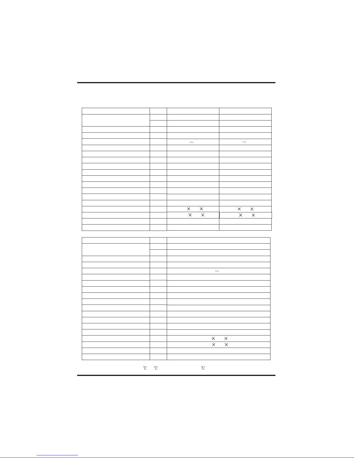
2.SPECIFICATION
2.1 Performance data of Swimming Pool Heat Pump Unit
*** REFRIGERANT : R410A
UNIT
Heating capacity
Heating Power Input
Running Current
Power Supply
Compressor Quantity
Compressor
Fan Number
Fan Power Input
Fan Rotate Speed
Fan Direction
Noise
Water Connection
Water Flow Volume
Water Pressure Drop(max)
Unit Net Dimensions(L/W/H)
Unit Ship Dimensions(L/W/H)
Net Weight
Shipping Weight
kW
Btu/h
kW
A
W
RPM
dB(A)
mm
3
m/h
kPa
mm
mm
kg
kg
956 375 623
1010 430 635
54
65
Heating: Outdoor air temp:24 /19 , Inlet water temp:26
UNIT
Heating capacity
Heating Power Input
Running Current
Power Supply
Compressor Quantity
Compressor
Fan Number
Fan Power Input
Fan Rotate Speed
Fan Direction
Noise
Water Connection
Water Flow Volume
Water Pressure Drop(max)
Unit Net Dimensions(L/W/H)
Unit Ship Dimensions(L/W/H)
Net Weight
Shipping Weight
kW
Btu/h
kW
A
W
RPM
dB(A)
mm
3
m/h
kPa
mm
mm
kg
kg
1116 500 886
1200 570 900
87
104
Oasis ELITE AC14
13.8
47000
2.1
10.4
230V /50Hz
1
rotary
1
120
850
horizontal
54
40
4.5
10
Oasis ELITE AC9
9.2
31400
1.5
6.7
230V /50Hz
1
rotary
1
120
850
horizontal
51
40
3.0
10
Oasis ELITE AC18
18.2
62000
3.0
13.4
230V /50Hz
1
rotary
1
150
850
horizontal
56
40
6.0
10
956 375 623
1010 430 635
61
72
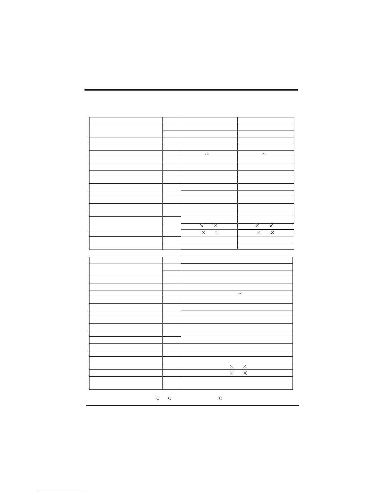
2.SPECIFICATION
2.1 Performance data of Swimming Pool Heat Pump Unit
*** REFRIGERANT : R410A
UNIT
Heating capacity
Heating Power Input
Running Current
Power Supply
Compressor Quantity
Compressor
Fan Number
Fan Power Input
Fan Rotate Speed
Fan Direction
Noise
Water Connection
Water Flow Volume
Water Pressure Drop(max)
Unit Net Dimensions(L/W/H)
Unit Ship Dimensions(L/W/H)
Net Weight
Shipping Weight
kW
Btu/h
kW
A
W
RPM
dB(A)
mm
3
m/h
kPa
mm
mm
kg
kg
Heating: Outdoor air temp:24 /19 , Inlet water temp:26
UNIT
Heating capacity
Heating Power Input
Running Current
Power Supply
Compressor Quantity
Compressor
Fan Number
Fan Power Input
Fan Rotate Speed
Fan Direction
Noise
Water Connection
Water Flow Volume
Water Pressure Drop(max)
Unit Net Dimensions(L/W/H)
Unit Ship Dimensions(L/W/H)
Net Weight
Shipping Weight
kW
Btu/h
kW
A
W
RPM
dB(A)
mm
3
m/h
kPa
mm
mm
kg
kg
1116 500 886
1200 570 900
87
104
Oasis ELITE AH18
18.2
62000
3.0
13.4
230V /50Hz
1
rotary
1
150
850
horizontal
56
40
6.0
10
Oasis ELITE AH14
13.8
47000
2.1
10.4
230V /50Hz
1
rotary
1
120
850
horizontal
54
40
4.5
10
Oasis ELITE AH9
9.2
31400
1.5
6.7
230V /50Hz
1
rotary
1
120
850
horizontal
51
40
3.0
10
3
956 375 623
1010 430 635
54
65
956 375 623
1010 430 635
61
72

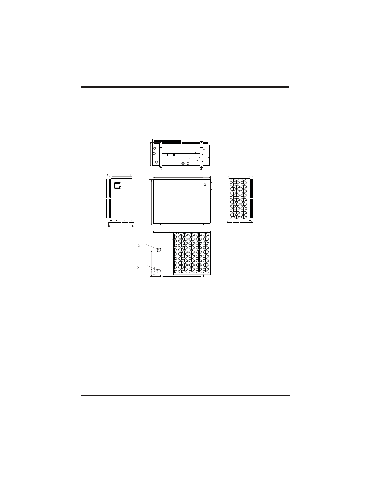
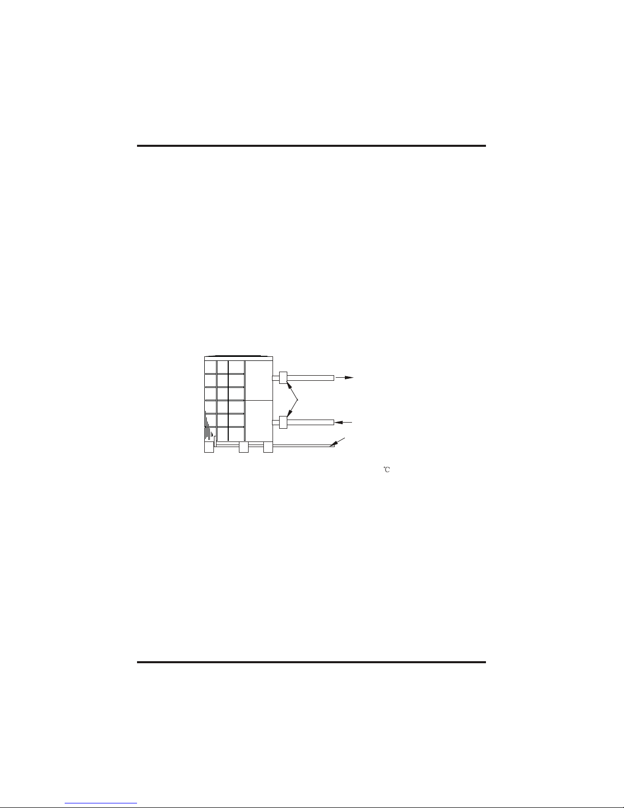
2.2 The dimensions for Swimming Pool Heat Pump Unit
2.SPECIFICATION
4
Oasis ELITE AC9/Oasis ELITEAC14/
375
623
956
552
Water inlet
40
Water outlet
40
114
350
356
18.5
Oasis ELITE AH9/Oasis ELITEAH14
Oasis ELITEAC18
5
2.SPECIFICATION
1116
886
500
790
460
511
400116
Water inlet
40
Water outlet
40
/ Oasis ELITEAH18
6
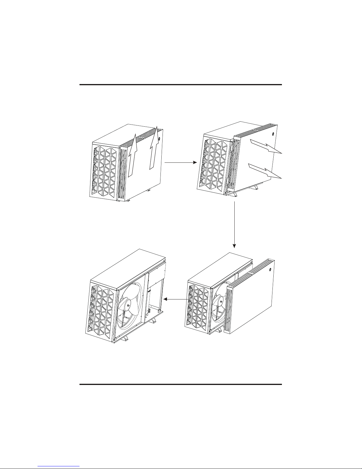
2.3How to disassemble the units.
2.SPECIFICATION
Attention: 1. Please be careful when handle with the front plate in case of damage;
2. During this process, please attention to protect the wire between the button
on the front plate and electrical box.
Pull up the
front plate
Move forward
the front plate
Take it of
7
2.SPECIFICATION
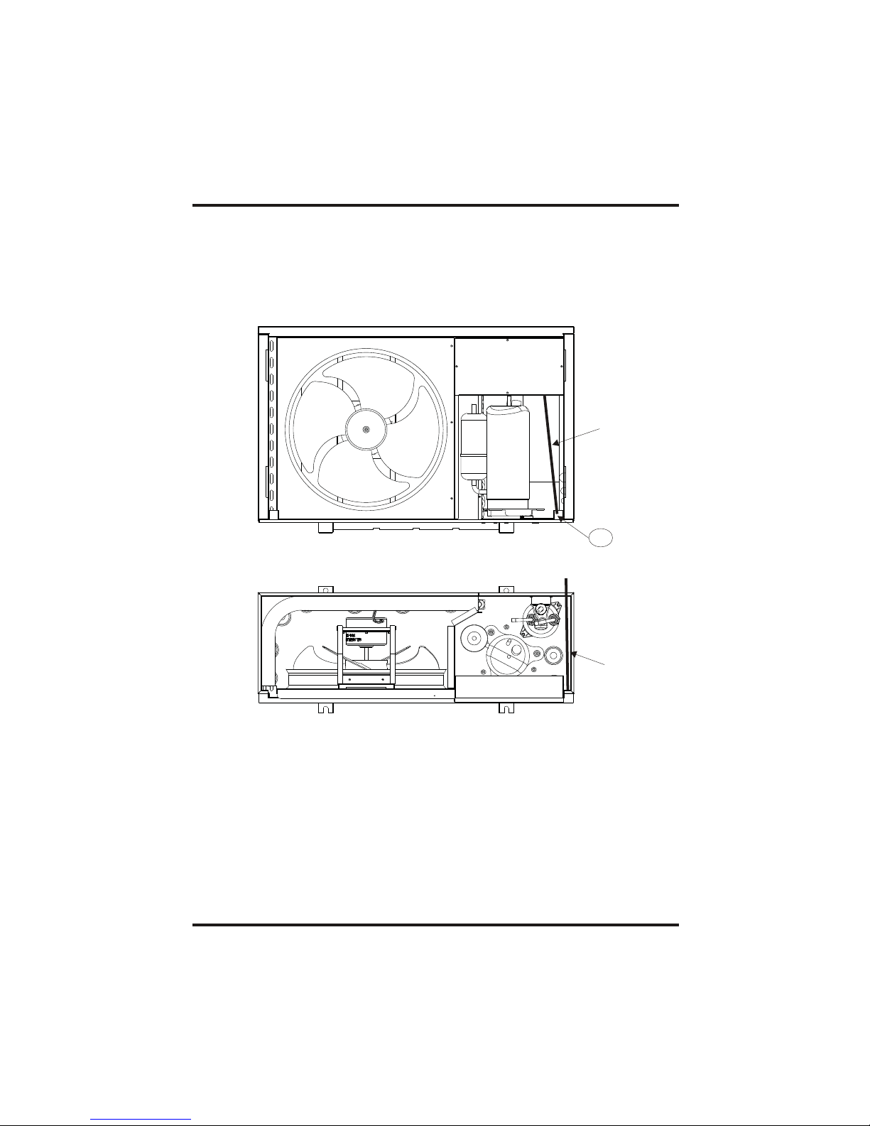
2.
1. Pull out power cord from the electrical box, and fix it at the place "A" as showed in the first
image below;
After fixing it at "A", draw it out from the bottom of the heat pump as showed in the second image.
A
Power cord
Power cord
2.4 How the power cord go
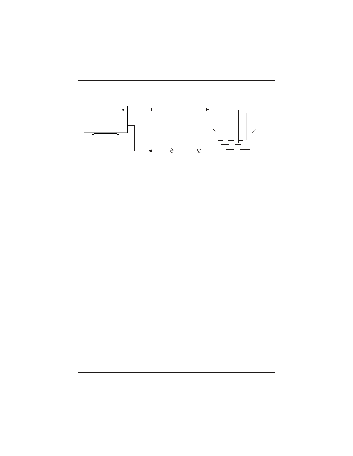
Installation items:
The factory only provides the main unit and the water unit; the other items in the illustration
are necessary spare parts for the water system ,that provided by users or the installer.
3.1 Installation illustration
Attention:
Please follow these steps when using for the first time
1.Open valve and charge water.
2.Make sure that the pump and the water-in pipe have been filled with water.
3.Close the valve and start the unit.
ATTN: It is necessary that the water-in pipe is higher than the pool surface.
3.INSTALLATION AND CONNECTION
8
Chlorinator cell
Water outlet
Pool
Val ve
Water supply
Water inlet
Water pump
Sand filter
(or other type filter)
The schematic diagram is for reference only. Please check the water inlet/outlet label on the
heat pump while plumbing installation.
The unit will perform well in any outdoor location provided that the following three factors are
presented:
1. Fresh Air - 2. Electricity - 3. Pool filter piping
The unit may be installed virtually anywhere outdoors. For indoor pools please consult the
supplier. Unlike a gas heater, it has no draft or pilot light problem in a windy area.
DO NOT place the unit in an enclosed area with a limited air volume, where the units
discharge air will be re-circulated.
DO NOT place the unit to shrubs which can block air inlet. These locations deny the unit of a
continuous source of fresh air which reduces it efficiency and may prevent adequate heat
delivery.
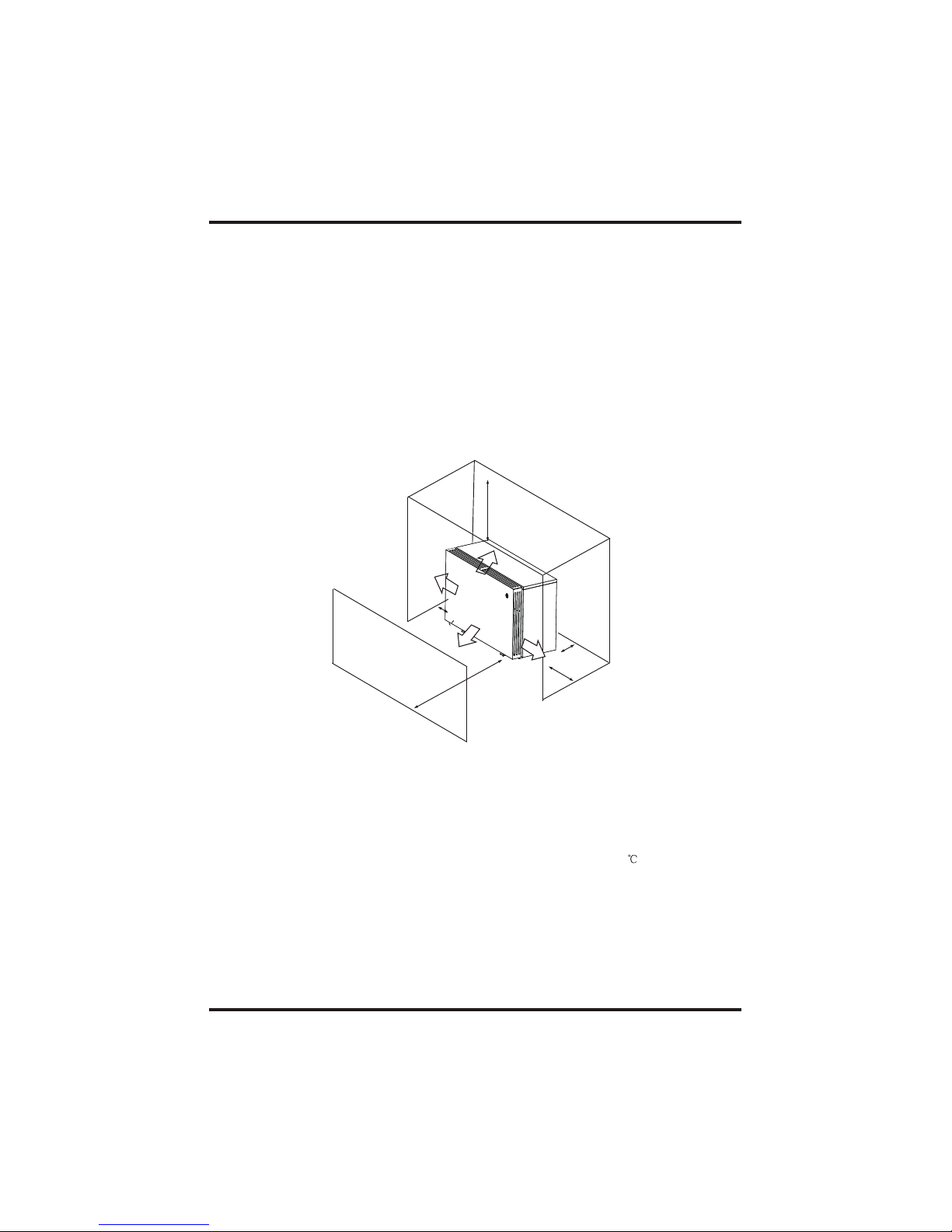
3.2 Swimming Pool Heat Pumps Location
Normally, the pool heat pump is installed within 7.5 metres of the pool. The longer the
distance from the pool, the greater the heat loss from the piping. For the most part ,the piping
is buried. Therefore, the heat loss is minimal for runs of up to15 meters(15 meters to and from
the pump = 30 meters total), unless the ground is wet or the water table is high. A very rough
estimate of heat loss per 30 meters is 0.6 kW-hour,(2000BTU) for every 5 difference in
temperature between the pool water and the ground surrounding the pipe, which translates to
about 3% to 5% increase in run time.
3.3 How Close To Your Pool?
9
3.INSTALLATION AND CONNECTION
Air inlet
Air outlet
300mm
700mm
300mm
500mm
700mm
3.4 Swimming Pool Heat Pumps Plumbing
Location: Connect the unit in the pool pump discharge (return) line downstream of all filter
and pool pumps, and upstream of any chlorinators, ozonators or chemical pumps.
Standard model have slip glue fittings which accept 32mm or 50 mm PVC pipe for
connection to the pool or spa filtration piping. By using a 50 NB to 40NB you can plumb 40NB
Give serious consideration to adding a quick coupler fitting at the unit inlet and outlet to allow
easy draining of unit for winterizing and to provide easier access should servicing be
required.
Condensation: Since the Heat pump cools down the air about 4 -5 , water may condense on
the fins of the horseshoe shaped evaporator. If the relative humidity is very high, this could
be as much as several litres an hour. The water will run down the fins into the basepan and
drain out through the barbed plastic condensation drain fitting on the side of the basepan.
This fitting is designed to accept 20mm clear vinyl tubing which can be pushed on by hand
and run to a suitable drain. It is easy to mistake the condensation for a water leak inside the
unit.
NB: A quick way to verify that the water is condensation is to shut off the unit and keep the
pool pump running. If the water stops running out of the basepan, it is condensation. AN
EVEN QUICKER WAY IS to TEST THE DRAIN WATER FOR CHLORINE - if the is no chlorine
present, then it's condensation.
3.INSTALLATION AND CONNECTION
10
To pool
From pump
PVC COUPLER
RECOMMENDED(Provided)
CONDENSATION
DRAIN
BARB FTG
The Swimming Pool Heat Pumps exclusive rated flow titanium heat exchanger requires no
special plumbing arrangements except bypass(please set the flow rate according to the
nameplate). The water pressure drop is less than 10kPa at max. Flow rate. Since there is no
residual heat or flame Temperatures, The unit does not need copper heat sink piping. PVC
pipe can be run straight into the unit.

3.5 Swimming Pool Heat Pumps Electrical Wiring
NOTE: Although the unit heat exchanger is electrically isolated from the rest of the unit, it
simply prevents the flow of electricity to or from the pool water. Grounding the unit is still
required to protect you against short circuits inside the unit. Bonding is also required.
3.INSTALLATION AND CONNECTION
3.6 Initial startup of the Unit
NOTE- In order for the unit to heat the pool or spa, the filter pump must be running to
circulate water through the heat exchanger.
Start up Procedure - After installation is completed, you should follow these steps:
1. Turn on your filter pump. Check for water leaks and verify flow to and from the pool.
2. Turn on the electrical power supply to the unit, then press the key ON/OFF of wire
controller, It should start in several seconds.
3. After running a few minutes make sure the air leaving the top(side) of the unit is
cooler(Between 5-10 )
4. With the unit operating turn the filter pump off. The unit should also turn off automatically,
5. Allow the unit and pool pump to run 24 hours per day until desired pool water emperature is
reached. When the water-in temperature reach setting, The unit just shuts off. The unit will
now automatically restart (as long as your pool pump is running)when the pool temperature
drops more than 2 below set temperature.
Time Delay- The unit is equipped with a 3 minute built-in solid state restart delay included to
protect control circuit components and to eliminate restart cycling and contactor chatter.
This time delay will automatically restart the unit approximately 3 minutes after each control
circuit interruption. Even a brief power interruption will activate the solid state 3 minute
restart delay and prevent the unit from starting until the 5 minute countdown is completed.
Power interruptions during the delay period will have no effect on the 3 minute countdown.
11
The unit has a separate molded-in junction box with a standard electrical conduit nipple
already in place. Just remove the screws and the front panel, feed your supply lines in
through the conduit nipple and wire-nut the electric supply wires to the three connections
already in the junction box (four connections if three phase). To complete electrical hookup,
connect Heat Pump by electrical conduit, UF cable or other suitable means as specified (as
permitted by local electrical authorities) to a dedicated AC power supply branch circuit
equipped with the proper circuit breaker, disconnect or time delay fuse protection.
Disconnect - A disconnect means (circuit breaker , fused or un-fused switch) should be
located within sight of and readily accessible from the unit, This is common practice on
commercial and residential air conditioners and heat pumps. It prevents remotely-energizing
unattended equipment and permits turning off power at the unit while the unit is being
serviced.
12
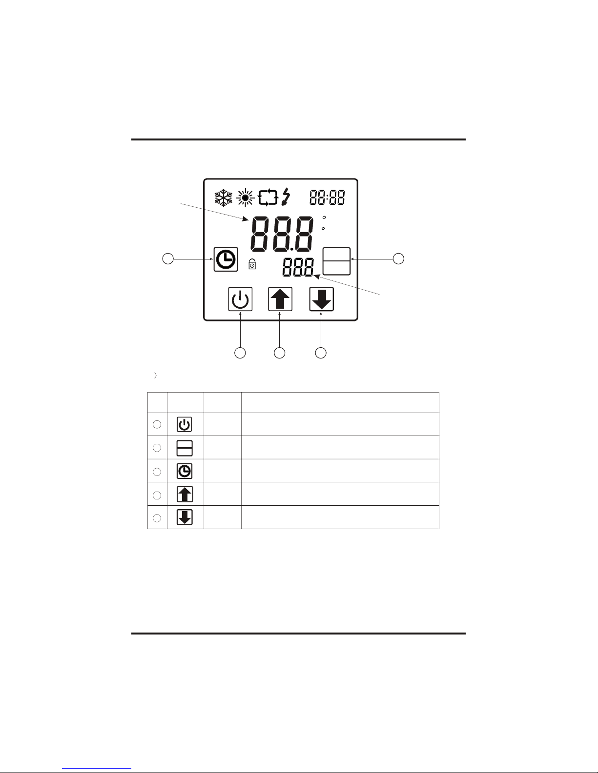
4. USAGE AND OPERATION
1.Function of controller
Main display area
Aux. Display area
1
2
3
4
1
4
5
3
TEMP
IN
SET
C
F
A
min
ON
OFF
TEMP
OUT
VOL
MODE
SET
2
MODE
SET
Clock
1 Button function
NO
Symbol
Name Function
On/off
Mode
Up
Press this button can start up or shut down the unit,
cancel the current operation or back to the upper
interface
Press this button can switch modes or save
parameter setting.
Press this button can move up or increase
parameter value.
Press this button can move down or decrease the
parameter value.
Down
5
Press this button can set the clock and timer
 Loading...