

Oasis DF-2801 Installation Manual

MODULAR WATER COOLERS and FOUNTAIN Models
®
DF-2801, DRF-7101HF, DRF-7101, DRF-7201HF, DRF-7201
OASIS
®
MMRSL, M8MREE, M8MR, M8WREE, M8WR, MWR, M8CREE, M8CR, MCR,
SUNROC
INSTRUCTIONS
1. INSPECTION
Inspect the cartons and various components for evidence of rough handling and concealed damage. Damage claims should be filed with the carrier.
2. MAINTENANCE (Fountains with Cooling Unit)
The only maintenance required is the re m oval of dirt and lint from the condense r. Inspec tion should be m ade at 3 m ount intervals. Rem ove the grille a nd cle an the c ondense r with a
vacuum attachment.
3. OVERLOAD PROTECTION (Fountains with Cooling Unit)
The compressor motor is equipped with an automa tic rese t protec tor which will disconne ct the motor from the line in case of overloa d.
4. LUBRICATION (Fountains with Cooling Unit)
This unit is equipped with a hermetically sea led com pressor. No additiona l lubrica tion is required. The fa n motor insta lled on this unit se ldom ne eds oiling. If re quired, a few
drops of SAE 10 oil should be used.
5. TO DISCONTINUE USE OF FOUNTAINS WITH COOLING UNITS
Drain cooler when removed from service: (1) R em ove grille , (2) Close supply va lve, (3) Provide conta iner to ca tch wa ter, a nd rem ove drain plug, (4) R em ove bubble r.
6. INSTALLATION, PLUMBING & ELECTRICAL CONNECTIONS
a) Note: The following states require a license d plumbe r to install c ooler; AR , GA, MA, MI, OK, R I, SC, SD, TX , VT and WI.
CA, KS, MN, NM and OR allow for a state -registe red installe r or contra ctor as w ell. Sta te a nd local plum bing c odes m ay prohibit the use of sa ddle ta pping valves for w ater
line connection in some applications. All conne ctions m ust conform to applic able plum bing code s.
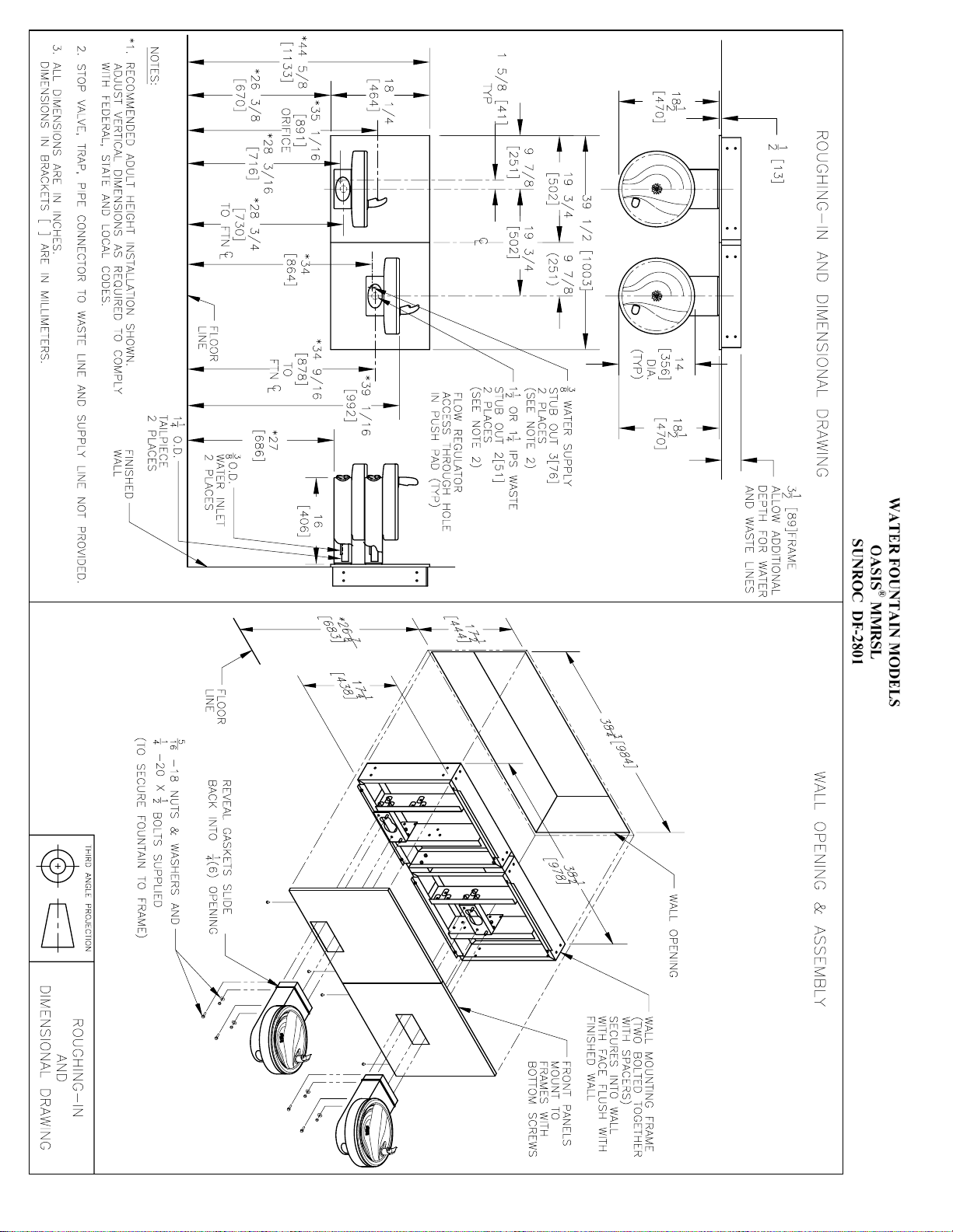
b) Plum bing rough-in and w all opening should be prepa red as show n on Roughing-in dra wing.
c) Insert frame assembly into wall opening and secure to studs. NOTE: FRONT FLANGE OF FRAME(S) MUST BE FLUSH WITH THE FINISHED WALL SURFACE.
d) Atta ch c radle m ounting angle s to unit mounting c radle with 4 scre ws provided. Slide unit m ounting cra dle into fram e a nd sec ure in place with 4 screws, provided. (Cradle is
used only when cooling unit is to be installed.) NOTE: BOTTOM FLANGE ON CRADLE IS TO BE BEHIND FRAME FRONT FLANGE.
e) Slide cooling unit onto cradle.
f) It is recommended that flexible conduit be used to supply power to the cooling unit (and to the electrica l box in the arm for t he se nsor and solenoid va lve on m odels w ith
electric eye). Check the electric current available. Type and voltage must be the same as listed on the unit data plate.
g) Place the upper panel(s) in place on the fram e top angle and fasten with 2 screws, provided, at the bottom.
h) R em ove the bottom pla te(s) from the founta in arm (s). Sa ve the sc rews.
i) Snap the reveal gasket(s) over the back end(s) of the fountain a rm(s).
j) Add compression connector(s), furnished by others, to the fountain wa ste tube (s) and slide ba ck a pproxima tely 3" out of the wa y . Use a 3/8 c ompression fitting for the water
line connections, provided by others. An internal straine r is provided for the wate r line conne ction. For dielec tric isola tion of the founta in(s) a non-m eta llic wate r line
connection can be used.
k) Ha ng the fountain(s) on the mounting pla te studs. NOTE: AS THE FOUNTAIN IS HUNG, FEED THE WASTE TUBE INTO THE WASTE STUB ON THE WALL
SIDE.
l) Tighten the fountain(s) to the mounting plate(s) with the 5/16-18 nuts and w ashers a nd the 1/4-20 bolts a nd washe rs provided.
m) Complete plumbing to the fountain(s). Tighten the wa ste c onnection(s) a nd then c onnect the wa ter supply line (s) with the 3/8 c ompre ssion fitting. When installing split le vel
models, hang the upper (short) fountain first, then connect the wa ter tube a ssem bly provide d to its wate r inlet. H ang the low e r (longer) founta in next and c onnec t the tube to
its water inlet supply line. For combination units with chillers, ha ng the upper (short) unit first a nd connec t the c hiller tube asse m bly, provide d, conta ining the te e to the
fountain water inlet tube with the compression fitting, provided, a nd then to the c hiller unit wate r out fitting. Ha ng the lower (longe r) unit next and c onnec t the long
connecting tube assembly, provided, to the te e a nd then to the founta in with the othe r com pression fitting.
n) On infra-red sensor equipped models, place and then hold hand approximately 3” from the sensor to actuate the solenoid valve, After approximately 30 seconds run time, the
sensor will automatically shut off the solenoid valve. To reactivate, move hand away for an instant and then again place it in front of the sensor. Repeat until the stream from
the bubbler is free of bubbles.
o) TO ADJUST THE BEAM RANGE OF THE SENSOR (EE Modes only): Shut off the wate r and powe r supplies.
p) Rem ove the three screws from the bottom of the bowl that holds the top to the bottom. These screws are recessed and located at the front and at the left and right rear of the
bowl bottom.
q) Lift the bowl top up to gain access to the sensor adjusting screw located between the two lenses.
r) The screw can be turned a maximum of ¾ turns. Turn screw counterclockwise to decre ase range. The se nsor has a n adjustable range of 24” to 48” . It is fac tory se t at 27”.
There is a non-adjustable on-time delay of 1. 5 sec onds to prevent nuisa nce a ctua tion of the solenoid va lve should som eone walk by . After drinking, the wa ter will shut off
immediately after walking aw ay. Maxim um run tim e is 30 seconds should som eone tam per w ith the sensor. NOTE : Walls with a reflective finish, i.e., ceramic tile, access
from the sensor may cause false actuation no matter what the sensor adjustment is for distance. Therefore, do not install the unit in such an area or dull the surface of the
walls so it will not reflect light.
s) Where applicable, secure the bottom panel(s) top edge(s) be hind the fram e m iddle cross m em ber(s) and fa sten the panel(s) a t the bottom to the fram e with the screws,
provided.
t) Slide the reveal gasket(s) back into the notch betwe en the pa nel a nd the arm . T he gaske t serve s as an a ppea rance item only (to c lose up a ny ope ning around the pa nel a nd the
mounting plate).
u) Che ck the plumbing c onnection for le aks. On ne w plum bing installations, run water through the bubbler(s) until the water ta ste is satisfac tory. Adjust regula tor to achie ve
desired stream height. Add the bottom plate (s) back to the fountain a rm(s).
The warranty and the Underwriters' La boratory L isting for this ma chine are a utomatic ally voide d if this ma chine is a ltered, m odified, or com bined with a ny other m ac hine or de vice.
Alteration or modification of this machine may cause serious flooding and/or hazardous electrical shock or fire.
EXCEPT AS SET FORTH HEREIN, THE MANUFACTURER MAKES NO OTHER WARRANTY, GUARANTEE OR AGREEMENT EXPRESSED, IMPLIED, OR STATUTORY,
INCLUDING ANY IMPLIED WARRANTY OR MERCHANTABILITY OR FITNESS FOR A PARTICULAR PURPOSE.
WARNING
222 East Campus View Blvd. • Columbus, OH 43235 U.S.A.
is a trademark of Oasis International © 2009 Oasis International
®
is a registered trademark of Oasis International 030099-233 Rev J
OASIS
1-800-950-3226
www.oasiscoolers.com
 Loading...