

Oase FiltoMatic CWS 7000, FiltoMatic CWS 14000, FiltoMatic CWS 25000 Operating Instructions Manual
Page 1
FiltoMatic CWS 7000/14000 /25000
Page 2
2
Page 3
3
Page 4
4
Page 5
5
Page 6
6
Page 7

- GB -
- GB -
Foreword
Welcome to OASE Living Water. You made a good choice with the purchase of this productFiltoMatic
CWS .
Prior to commissioning the unit, please read the instructions of use carefully and fully familiarise yourself
with the unit. Ensure that all work on and with this unit is only carried out in accordance with these
instructions.
Adhere to the safety information for the correct and safe use of the unit.
Keep these instructions in a safe place! Please also hand over the instructions when passing the unit on
to a new owner.
Table of Contents
1 Scope of delivery.............................................................................................................................. 23
2 Overview .......................................................................................................................................... 23
3 Legal conditions ............................................................................................................................... 23
4 Safety information ............................................................................................................................ 24
5 Installation ........................................................................................................................................ 25
6 Installation ........................................................................................................................................ 26
7 Start-up............................................................................................................................................. 27
8 Operation.......................................................................................................................................... 28
9 Remedy of faults .............................................................................................................................. 31
10 Maintenance and cleaning ............................................................................................................... 32
11 Wear parts........................................................................................................................................ 36
12 Storage/Over-wintering .................................................................................................................... 36
13 Disposal............................................................................................................................................ 36
Technical data ........................................................................................................................................ 337
Symbols on the unit................................................................................................................................ 341
Spare parts ............................................................................................................................................. 342
3.1 Intended use ............................................................................................................................ 23
3.2 Extended guarantee conditions for the OASE ClearWaterSystem.......................................... 23
4.1 Hazards encountered by the combination of water and electricity .......................................... 24
4.2 Correct electrical installation .................................................................................................... 24
4.3 Safe operation.......................................................................................................................... 24
8.1 Controller overview .................................................................................................................. 28
8.2 Setting the dirty water pump ....................................................................................................29
8.3 Setting the UVC clarifying unit .................................................................................................30
10.1 Cleaning foam filters ................................................................................................................ 32
10.2 Remove and separate the cleaning components from each other .......................................... 32
10.3 Cleaning the dirty water pump ................................................................................................. 33
10.4 Changing the UVC lamp in the UVC clarifying unit.................................................................. 33
10.5 Checking the cleaning rotor .....................................................................................................34
10.6 Changing the foam filters ......................................................................................................... 34
10.7 Thorough cleaning of the unit .................................................................................................. 35
22
Page 8

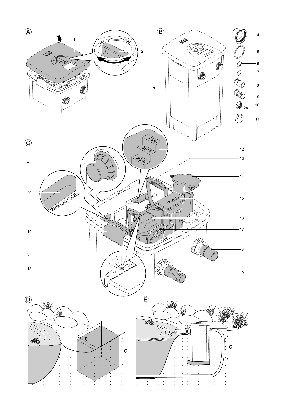
1 Scope of delivery
► Open the lid (1) using the rotary handle (2) to remove the assembly components (Figure A).
Figure B Number Description
3 1 Container FiltoMatic CWS
4 1 Outlet DN70
5 1 Flat sealing DN70
6 1 Flat sealing 1 ½“
7 1 O ring DN40
8 1 Outlet sheath DN40
9 1 Inlet sheath 1 ½“
10 2 Union nut
11 1 Hose clip
1 Instructions for use
1 Fast assembly instruction manual
1 Guarantee brochure
1 Clear water guarantee card
1 Guarantee extension card 2+1
2 Overview
Figure C Designation For a description, please refer to Chapter …
3 Container Assembly, cleaning and maintenance
4 Outlet DN70 Installation
8 Dirty water outlet DN40 Installation
9 Inlet 1 ½“ Installation
12 Soiling indicator Maintenance and cleaning
13 Foam holder Maintenance and cleaning
14 Dirty water pump Maintenance and cleaning
15 Controller Operation
16 UVC clarifying unit Maintenance and cleaning
17 Stop valve for inlet Starting up, cleaning and maintenance
18 UVC lamp control window Maintenance and cleaning
19 Engagement hooks Maintenance and cleaning
20 Biokick CWS infill opening Start-up
- GB -
3 Legal conditions
3.1 Intended use
The FiltoMatic CWS is intended as a filter system for the mechanical and biological cleaning of garden
ponds having a water temperature of between +4 °C and +35 °C. The unit is exclusively suited for
private use and may only be employed for cleaning garden ponds with or without fish population.
3.2 Extended guarantee conditions for the OASE ClearWaterSystem
Guarantee claims can only be brought forward to us, OASE GmbH, Tecklenburger Straße 161 in
D-48477 Hörstel, by returning to us the unit or part of the unit subject to complaint, freight free, at your
own risk, accompanied by the original purchase receipt from the OASE specialist dealer, this guarantee
document and written information of the fault encountered. Should the dirty water pump, UVC clarifying
unit or controller be defective, only return the individual defective component (dirty water pump, UVC
clarifying unit, controller), not the complete unit.
23
Page 9

- GB -
4 Safety information
Hazards to persons and assets may emanate from this unit if it is used in an improper manner or not in
accordance with its intended use, or if the safety instructions are ignored.
This unit can be used by children from the age of 8 and by persons with physical,
sensory or mental impairments or lack of experience and knowledge, as long as they
are supervised or instructed on how to use the unit safely and are able to understand
the potential hazards. Do not allow children to play with the unit. Do not allow children
to clean or maintain the unit without close supervision.
4.1 Hazards encountered by the combination of water and electricity
► The combination of water and electricity can lead to death or severe injury from electrocution, if the
unit is incorrectly connected or misused.
► Prior to reaching into the water, always switch off the mains voltage to all units used in the water.
4.2 Correct electrical installation
► For your own safety, consult a qualified electrician when you have questions or encounter problems.
► Electrical installations at garden ponds must meet the international and national regulations valid for
installers. Especially adhere to DIN VDE 0100 and DIN VDE 0702.
► Compare the electrical data of the power supply with those indicated on the type plate on the UVC
clarifying unit.
► Only operate the FiltoMatic CWS when plugged into a correctly fitted socket.
► Please note that the power supply must be fused via a fault current protection system with a
maximum reference fault current of 30 mA.
► Install the FiltoMatic CWS such that any risk of injury to persons is excluded.
► Only use cables that are uncoiled.
► Extension cables must be approved for outdoor use and meet DIN VDE 0620 standards.
► Route the connection cable so that damage is excluded.
► Keep all connection points dry. Risk of electrocution.
4.3 Safe operation
► Only operate the FiltoMatic CWS if no persons are in the water.
► Never carry or pull the UVC clarifying unit and the dirty water pump of the FiltoMatic CWS by holding
on the connection cables.
► Do not operate defective units. Do not operate the FiltoMatic CWS if the electrical connection cables
are defective. Pull the power plug immediately. The connection cables of the UVC clarifying unit and
of the dirty water pump cannot be repaired. Replace the components. Dispose of the defective
components in compliance with the environmental regulations.
► Never open the housing of the UVC clarifying unit, dirty water pump, control system or their
attendant components, unless this is explicitly mentioned in these instructions of use.
► Only use original spare parts and accessories.
► Never use the system for filtering fluids other than water.
► The radiation of the UVC lamp, even in small doses, is dangerous for eyes and skin. Never operate
the UVC lamp in a defective housing or outside of the housing.
► Never operate the UVC lamp without cleaning rotor, as this also acts as an eye protection against
UVC radiation.
► Overvoltage in the mains could lead to operating malfunctions of the unit. For information, please
refer to chapter "Remedy of faults".
24
Page 10

5 Installation
We recommend to thoroughly clean the garden pond to ensure almost maintenance-free operation of
the FiltoMatic CWS from the very beginning. OASE's recommendation for this cleaning work is the use
of the pond sludge suction unit Pondovac. In general, cleaning work can be omitted when the FiltoMatic
CWS is used in a newly installed garden pond.
Installing the FiltoMatic CWS (Figure D,E)
Plan the installation of the FiltoMatic CWS. Careful planning and taking the environmental conditions
into account will lead to optimum operating conditions for the FiltoMatic CWS. The following points can
help you with your planning.
► A water course guarantees optimum water return from the FiltoMatic CWS to the garden pond. In
this manner, the filtered pond water is enriched with oxygen prior to returning to the pond. Should
the local situation not allow the installation of a water course, extend the outlet using a DN70 pipe for
the filtered water to return to the pond via the pipe. Please refer to the Installation chapter for the
installation of a DN70 pipe.
► Horizontal alignment of the FiltoMatic CWS is crucial to prevent drainage of the pond in the event of
an overflow. Carry out the alignment using a spirit level.
► Take the large volume of the FiltoMatic CWS as well as the resulting weight when filled into account.
Select a suitable ground or a bottom slab in the pit to prevent the FiltoMatic CWS from sagging.
► Plan sufficient space for movement to be able to carry out cleaning and maintenance work.
► Dig a suitably dimensioned pit for the installation of FiltoMatic CWS (Figure D). Take into
consideration that the FiltoMatic CWS can be buried up to the top recess (Figure E, height c).
Please use the following table as a basis for the pit dimensions:
Model a b c (+ bottom slab height)
FiltoMatic CWS 7000 approx. 50 cm approx. 50 cm approx. 30 cm
FiltoMatic CWS 14000 approx. 50 cm approx. 50 cm approx. 50 cm
FiltoMatic CWS 25000 approx. 50 cm approx. 70 cm approx. 50 cm
► Fill the container (3) with water prior to backfilling the soil to avoid compressing the container.
► Route the DN40 pipe end for the dirty water outlet at a distance from the pond that prevents the
pumped out dirty water from flowing back into the pond.
- GB -
25
Page 11

- GB -
6 Installation
Installation of the FiltoMatic CWS
The FiltoMatic CWS is delivered pre-assembled. Assembly is reduced to the outlet and the inlet and
dirty water outlet connections.
The outlet sheath (8) for the dirty water outlet is transparent. In this manner, the degree of soiling of the
outflowing water is visible during future cleaning. Pumping can be stopped as soon as visibly clean
water flows out of the dirt outlet. Cleaning is then completed.
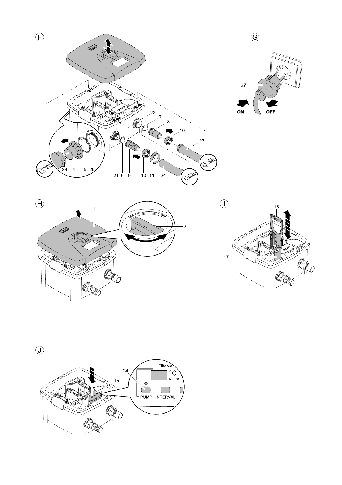
Installation of the outlet (Figure F)
1. Place the flat sealing (5) over the outlet screw (25) pre-fitted on the housing.
2. Screw the outlet (4) on the outlet screw (25).
3. If necessary, connect a DN70 pipe (26) to the outlet (4) as an extension to allow the filtered pond
water to return into the pond. Ensure a minimum incline of 1.5 % for the DN70 pipe.
As an extension for the outlet, OASE recommends the following:
− DN70 pipe, 480 mm, black (OASE Order No. 55034)
− DN70 pipe elbow, 45°, black (OASE Order No. 55044)
− DN70 pipe elbow, 87°, black (OASE Order No. 55045)
− DN70 pipe elbow, T, black (OASE Order No. 55046)
Installation of the inlet (Figure F)
1. Plug the inlet sheath (9) and the flat sealing (6) into the union nut (10) and tighten at the stop valve
thread (21).
2. Slide the hose clip (11) over the hose (24) arriving from the Aquamax. Push the hose on the inlet
sheath (9) and fasten with the hose clip.
Hose recommended by OASE: Spiral hose, green (OASE Order No. 52981)
Prior to the assembly, place the hose end in hot water for two minutes. It will then be easier to slide the
hose onto the inlet sheath (9).
Installation of the dirty water outlet (Figure F)
1. Fit the O ring (7) on the outlet sheath (8) and into the union nut (10). Then tighten to the thread of
the pre-assembled dirty water outlet (22).
2. Plug a DN40 pipe (23) onto the outlet sheath (8). Route the end of the DN40 pipe to a point where
the dirty water to be pumped out can trickle into the ground. Ensure a gravity of 1.5 % to 2 % for the
DN40 pipe.
As an extension for the dirty water outlet, OASE recommends the following:
− DN40 pipe, 480 mm, black (OASE Order No. 50307)
− DN40 pipe elbow, 45°, black (OASE Order No. 50308)
26
Page 12

7 Start-up
Attention! Sensitive electrical components.
Possible consequence: The unit will be destroyed.
Protective measure:
► Do not connect the unit to a dimmable power supply.
► Do not operate the unit with a timer.
Attention! Dangerous electrical voltage.
Possible consequences: Death or severe injury.
Protective measures: Disconnect the power plug (Figure G) prior to reaching into the water and
commencing work.
Follow the safety information!
The FiltoMatic CWS switches on automatically when the power connection is established.
Switching on (Fig. G): Plug the power plug (27) into the socket.
Switching off (Fig. G): Disconnect the power plug (27).
Fill the container with water (Figure C)
► Switch the Aquamax pump on prior to commissioning the FiltoMatic CWS. Container (3) has to be
filled with water.
- GB -
Stop valve (17) needs to be open to enable the container to be filled. For this purpose, press the stop
valve (17) down against the stop.
As soon as the water level in the container (3) reaches the outlet (4), the filtered pond water returns into
the pond via the outlet (4).
For further settings of the FiltoMatic CWS, please read the following Chapter Operation.
Filling with biological filter starter (Figure C)
We recommend the OASE filter starter Biokick CWS (OASE Order No. 50295) for a fast growth of
bacteria populations. Micro-organisms colonise the filter system, multiply and ensure an enhanced
quality of the pond water by the decomposition of excess nutrients.
► Fill the quantity of Biokick CWS sufficient for the volume of your pond into the infill opening (20).
27
Page 13

- GB -
8 Operation
8.1 Controller overview
Displays on the controller
The display (C1) shows
− the water temperature as standard.
− automatically the water temperature again 2 seconds after the last key operation.
− the cleaning programs if selected accordingly.
− the saved settings when pressing a key.
− the remaining operating life (h × 100) of the UVC lamp.
Displayed messages (C1)
− "LA" flashes in an 8 sec. interval 1×: The UVC lamp was active for 7500 operating hours; remaining operating life: 500
operating hours
− "LA" flashes in an 8 sec. interval 2×: The UVC lamp has operated for 8000 hours and should be replaced.
− "PS" lights up in a 4 sec. interval: The dirty water pump has reached its max. running time and is blocked for 1.5 hours.
LED for dirty water pump (C2)
− LED flashes green: Partial container drainage.
− LED is lit green: complete container drainage.
− LED is lit red: Pump blocked.
− LED off: Pump not active.
LED for UVC clarifying unit (C3)
− LED is lit blue: UVC clarifying unit is switched on.
− The LED flashes in an 8 sec. interval blue: The UVC clarifying unit is integrated in the Automatic (AU) operating program.
− LED off: UVC clarifying unit is switched off.
Note:
The integrated thermometer permanently measures the water temperature, thereby forming the reference value for the operating
programs.
The silicone cover protects the controller from soiling; it impairs neither the display reading nor the functionality of the keys. The
controller is water tight and can also be operated without the silicone cover.
C1 Display
C2 LED displaying the dirty water
pump function
C3 LED displaying the UVC
function
C4 Key for manual dirty water
pump operation
C5 Key for setting a cleaning
program for the dirty water
pump
C6 Key for setting an operating
program for the UVC clarifying
unit
28
Page 14

8.2 Setting the dirty water pump
In addition to the water temperature, the degree of soiling of the pond water greatly depends on the fish
population. The dirty water pump pumps out the dirt from the container bottom in intervals. The four
different cleaning programs allow individual adaptation of the interval for pumping off the dirty water
according to the degree of soiling. One cleaning cycle takes approx. 9 sec. and requires approx. 4 litres
of water. The table shows the cleaning program selection options. The cleaning program INTERVAL 1
includes the majority of cleaning intervals, INTERVAL 4 the smallest number of intervals. Select a
program that is best suited for the degree of soiling of the pond water. When delivered, cleaning
program INTERVAL 2 is set as a default.
Water temperature
INTERVAL 1 INTERVAL 2 INTERVAL 3 INTERVAL 4 OFF
< 5 °C
< 8 °C
8 °C - 14 °C 2 × per day 1 × per day every 2 days every 3 days off
15 °C - 21 °C 4 × per day 2 × per day 1 × per day every 2 days off
≥ 22 °C
off off off off off
1 × per day every 2 days every 3 days every 3 days off
8 × per day 4 × per day 2 × per day 1 × per day off
The cleaning programs are inactive at water temperatures between <0 °C and >35 °C. The pump can
then only be actuated manually. For fully pumping out, keep the PUMP (C4) key permanently pressed.
Setting the cleaning program for the dirty water pump
1. Press the INTERVAL (C5) key. The cleaning program INTERVAL 2 appears in the display (C1).
2. Press the INTERVAL (C5) key until the desired cleaning program appears.
3. Release the INTERVAL (C5) key when the desired cleaning program is displayed.
− The setting is saved when the water temperature appears in the display (C1) after a period of
approx. 2 seconds.
Manual pumping out of the dirty water
The dirty water can also be removed by pumping manually.
► Press the PUMP (C4) key
− The LED (C2) flashes green. Soiling removal starts immediately.
+ Intervals
- GB -
Cleaning programs, dirty water pump
− Intervals
► Complete container emptying starts when you keep the PUMP (C4) key pressed for longer than 10
seconds. The green LED (C2) is lit. The dirty water pump runs for a maximum of 4 minutes. You can
stop the drainage cycle by pressing the PUMP (C4) key once.
► The maximum running time of the dirty water pump is limited to 12 minutes per 1.5 hours in order to
avoid damage resulting from overheating. With heavy soiling, the running time can also be limited to
8 minutes. Once the max. running time is reached; the pump can no longer be operated manually.
The display shows "PS". After 1.5 hours the dirty water pump is once again operational.
29
Page 15

- GB -
8.3 Setting the UVC clarifying unit
The degree of soiling of the pond water by the formation of algae is notably determined by the water
temperature. With its UV light, the UVC clarifying unit operating under water removes green algae, as
such forming a significant component for pond water cleaning. Depending on the water temperature, the
UVC lamp of the UVC clarifying unit is switched on and off in intervals with the AU operating program. In
this manner it can be individually adapted to the degree of soiling. The following table shows the
operating program AU (Automatic) of the UVC clarifying unit as well as the operating statuses ON and
OFF.
Water temperature
UVC lamp is switched
< 8 °C
8 °C - 14 °C 48 h 24 h
15 °C - 21 °C 72 h 24 h
≥ 22 °C
on
8 h 16 h
96 h 24 h
When delivered, the operating program AU is set as a default.
► With Power ON, the operating program AU starts with the OFF interval. The UVC lamp does not lit
up for a minimum of 16 hours. The use of Biokick CWS during start-up protects the bacteria cultures
in the Biokick CWS.
► The UVC clarifying unit starts with the ON interval when the AU operating program is manually
selected.
Setting the operating program for the UVC clarifying unit
1. Press the UVC (C6) key. The AU operating program appears on the display (C1).
2. Press the UVC (C6) key until the desired operating program is displayed.
3. Release the UVC (C6) key when the desired operating program is displayed.
− The setting is saved when the water temperature appears in the display (C1) after a period of
approx. 2 seconds.
Inquiry of the operating hour counter reading of the UVC clarifying unit
The operating life of a UVC lamp for the UVC clarifying unit is approx. 8000 hours. The integrated
operating hour counter counts down from this value.
► Keep the UVC (C6) key pressed for 5 seconds. A number appears in the display (C1).
− Multiply this number by 100 to calculate the remaining number of operating hours.
− Example: displayed value '45' × 100 = 4500 remaining operating hours.
Resetting the operating hour counter reading of the UVC clarifying unit
Reset the operating hour counter after changing a UVC lamp.
1. Keep the UVC (C6) key pressed for 12 seconds!
− The remaining operating life appears on the display (C1) after 5 seconds. Following this, the
display flashes. The operating hour counter is reset to 8000 hours, when the water temperature
appears in the display (C1).
2. Release the UVC (C6) key.
UVC clarifying unit operating programs
AU ON OFF
UVC lamp is switched
off
UVC lamp is
permanently switched
on
UVC lamp is
permanently switched
off
30
Page 16

- GB -
9 Remedy of faults
Malfunction Cause Remedy
The controller does not switch on
to the pond
Dirty water pump does not switch on
No mains voltage Check mains voltage
Check supply lines
Controller incorrectly positioned on the UVC
Check the controller seating
clarifying unit
Aquamax pump not switched on Switch on Aquamax pump Water from the DN70 outlet does not return
Stop valve closed with the lid open Open stop valve
Pump rotor blocked Clean pump rotor
Container already empty Fill container
Container partly emptied, dirty water pump
Fill container
cannot prime
The cleaning programs are inactive at water
temperatures between<0 °C and >35 °C
Now the dirty water pump can only be
operated manually.
− Keep the PUMP key pressed for complete
drainage.
The dirty water pump has reached its max.
running time. The display shows "PS".
Wait for 1.5 hours. Once this time has
elapsed, the dirty water pump is operational
again.
UVC lamp defective Changing the UVC lamp UVC lamp does not switch on
The safety system in the UVC clarifying unit
has tripped as a result of overvoltage in the
mains
Switch of the mains voltage and on again to
reset the safety system
− Check that the UVC lamp is lit in the
control window (blue light)
− To test, we suggest to switch on the UVC
lamp using the UVC key (operating status
ON)
31
Page 17

- GB -
10 Maintenance and cleaning
Attention! Dangerous electrical voltage.
Possible consequences: Death or severe injury.
Protective measures:
► Prior to reaching into the water, switch off the mains voltage to all units used in the water.
10.1 Cleaning foam filters
► Switch off the mains voltage prior to carrying out work on the unit.
Cleaning intervals depend on the degree of soiling of the foam filters. A higher water level in the soiling
indicator (Figure C, 12) in the inner cover signals that the foam filter cleaning capacity has decreased.
Cleaning is due from a degree of soiling of 75 % or in the event of an overflow at the latest.
How to clean the foam filters (Fig. H, I, J)
1. Open lid (1) with the rotary handle (2) and remove lid from the container (3).
2. Close the stop valve (17) by pulling it up.
− Pond water no longer flows into the container.
− Note: Water will spurt out of the air intake socket when closing the stop valve (17).
3. Pull foam filters (13) up several times.
− The foam filters will be compressed. The soiling will be washed out.
4. Press the PUMP key (C4) on the controller (15) for longer than 10 seconds.
− The LED (C2) is lit green. All of the dirty water in the container will be pumped out.
5. Open the stop valve (17) by pressing it down.
− The container fills up with pond water again.
Repeat the cleaning cycle if the foam filters are heavily soiled.
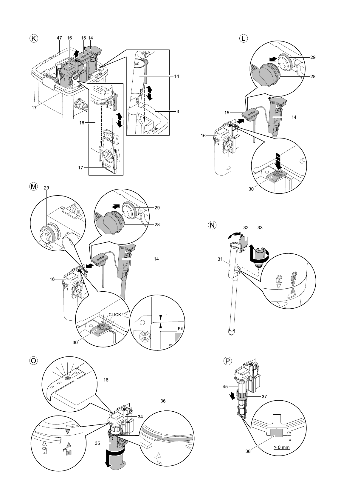
10.2 Remove and separate the cleaning components from each other
For cleaning and maintenance of the cleaning components of the dirty water pump (14) and the UVC
clarifying unit (16) it is necessary to take both out of the container. The controller (15) is fitted to the UVC
clarifying unit. The cleaning components are not permanently connected to the inner cover (47) but rest
in the guides of the inner cover (47) or of the stop valve (17) respectively.
This is how to remove the cleaning components (Figure K)
1. Open lid (1) with the rotary handle (2) and remove lid from the container (3) (Figure H).
2. Close the stop valve (17) by pulling it up.
− Pond water no longer flows into the container.
− Note: Water will spurt out of the air intake socket when closing the stop valve.
3. Lift the cleaning components of the dirty water pump (14) and of the UVC clarifying unit (16) out of
the inner cover (47) as one unit.
This is now the cleaning components and the controller are separated from one another (Figure
L)
1. Keep the engagement hook (30) on the UVC clarifying unit (16) pressed.
2. Remove the controller (15) from the UVC clarifying unit by applying force.
3. Pull the connection cable (28) of the dirty water pump off the controller (15) by applying force.
4. Plug in the silicone caps to protect the open sockets.
5. Reassemble the cleaning components and the controller in the reverse order (Figure M).
− When assembling the controller and the UVC clarifying unit, ensure that the arrows on both
components point to one another.
During assembly, check the seating of the O rings (29) at the connection points of the controller and of
the UVC clarifying unit! Clean the O rings (29) as required. The electrical contacts will corrode if the O
rings are missing or incorrectly seated. This will lead to irreparable damage to the components!
32
Page 18

10.3 Cleaning the dirty water pump
Cleaning of the dirty water pump becomes due when the rotor of the pump motor (33) is heavily soiled
or blocked. This can happen as a result of larger soiling, such as, e.g. stones. The LED indicator (C2) on
the controller (15)
How to clean the dirty water pump (Fig. N)
1. Turn the motor housing (33) until the symbol showing " Lock open" points to the arrow on the top
pipe (31).
2. Remove and clean the motor housing (33).
3. Reassemble in the reverse order.
− Important: The motor housing (33) is only arrested when the "Lock closed" symbol points to the
arrow on the top pipe (31) (Figure N).
4. Press the PUMP button (C4) once.
− The LED (C2) changes from red to green. The dirty water pump (14) starts up. Otherwise, the dirty
water pump (14) will not start up because of a malfunction. In this context, please refer to Chapter
Remedy of faults.
5. If necessary, clean the overflow on the top pipe (31). To this effect, open the soiling pipe cover (32).
10.4 Changing the UVC lamp in the UVC clarifying unit
Attention! Dangerous ultra-violet radiation.
Possible consequences: Severe injury to the eyes and the skin.
Protective measures: Only switch the unit on with the housing fitted.
The controller (15) does not show when the UVC lamp is defective. Check the function of the UVC lamp
by looking into the control window (18) at regular intervals (Figure O).
The operating life of the UVC lamp being limited, it has to be replaced once its useful life has elapsed
(please also refer to Chapter Checking the reading of the UVC clarifying unit operating counter).
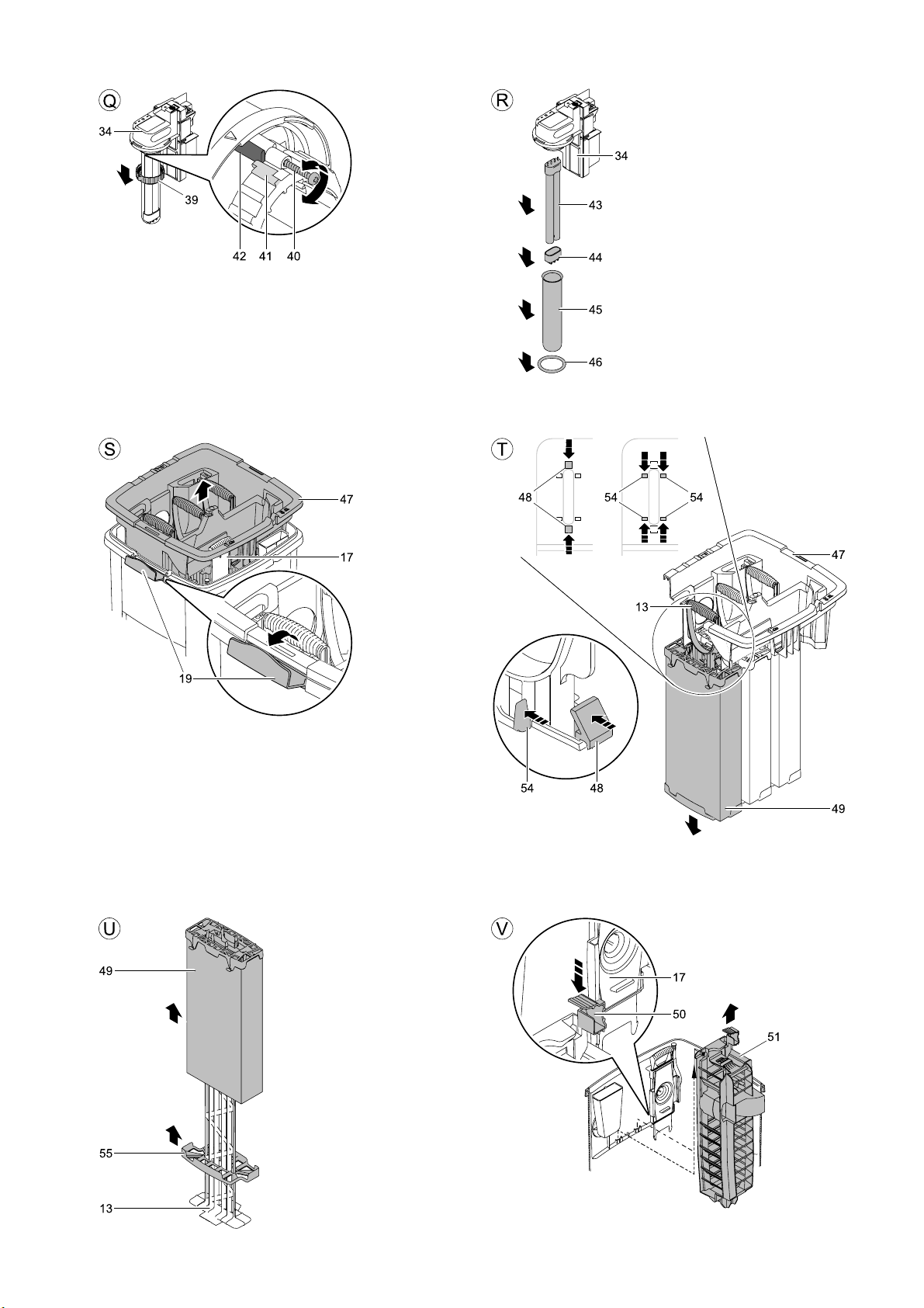
1. Turn the water housing (35) until the symbol showing " Lock open" points to the arrow at the UVC top
pipe (34) (Figure O).
2. Pull off the water housing (35) (Figure O).
3. Remove the cleaning rotor (37) from the quartz glass tube (45) (Figure P).
4. Loosen the screw (40) from the union nut (39), then unscrew the union nut (39) (Figure Q).
5. Pull off the quartz glass tube (45) including the O ring (46) by a rotary movement (Figure R).
6. Pull off the UVC lamp protection (44) (Figure R).
7. Pull the UVC lamp (43) out of its position in the UVC top section (34) and replace (Figure R).
8. Reassemble the UVC clarifying unit in the reverse order.
− Important: The water housing (35) is only closed when the "Lock closed" symbol points to the
arrow on the UVC top section (34) (Figure O).
- GB -
► During assembly ensure that the stop (41) of the union nut (39) butts against the stop (42) on the
UVC top section (34). Only then can the screw (40) be turned in (Figure Q).
► The O ring (36) on the water housing closure (35) is firmly clamped on. Only remove the O ring (36)
if it needs replacing, e.g. has become brittle (Figure O).
► Condensate forms in the quartz glass tube (45). This condensate cannot be avoided, however, it
does not impair function and safety.
► The quartz glass tube (45) can become scratched or blind over time. In this case, sufficient cleaning
performance of the UVC lamp (43) is no longer guaranteed. The quartz glass tube (45) must be
replaced.
33
Page 19

- GB -
10.5 Checking the cleaning rotor
The cleaning rotor (37) cleans the quartz glass tube (45). The rotor is driven by the water flow in the
water housing (Figure P).
The constant rotational movement of the cleaning rotor (37) causes wear of the bearing bush (38). In
this case, the cleaning rotor (37) needs replacing (Figure P).
1. Turn the water housing (35) until the symbol showing " Lock open" points to the arrow at the UVC top
pipe (34) (Figure O).
2. Pull off the water housing (35) (Figure O).
3. Check the wearing condition of the bearing bush (38).
− When the bearing bush (38) has worn down to 0 mm, the cleaning rotor (37) needs to be
replaced (Figure P).
4. Reassemble the UVC clarifying unit in the reverse order.
− Important: The water housing (35) is only closed when the "Lock closed" symbol points to the
arrow on the UVC top section (34) (Figure O).
10.6 Changing the foam filters
We recommend to change the foam filters (49) once per year.
How to change the foam filters:
1. Open lid (1) with the rotary handle (2) and remove lid from the container (3) (Figure H).
2. Close stop valve (17) by pulling it up (Figure S).
− Pond water no longer flows into the container.
− Note: Water will spurt out of the air intake socket when closing the stop valve (17).
3. Pull up the foam holder (13) in the inner cover (47) several times. The water in the foam filters (49) is
pressed out (Figure I).
4. Press the PUMP key (C4) on the controller (15) for longer than 10 seconds (Figure J).
− The LED (C2) is lit green. The dirty water in the container will be pumped out.
5. Lift the cleaning components of the dirty water pump (14) and of the UVC clarifying unit (16) out of
the inner cover (47)(Figure K).
6. Release the blue engagement hooks (19) on both sides, and then remove the inner cover (47)
including the foam holders (13) out of the container (Figure S).
7. Slightly lift the foam holder (13), press together the two blue engagement hooks (48) at the foam
holders (13), then push the foam holders downward and out of the inner cover (47) (Fig. T).
8. Press in the four black engagement hooks (54) at the upper part of the foam and take out the foam
holder (13) downward including the filter cartridge (49) (Fig. T).
− Note: Press together the engagement hooks (54) arranged opposite of each other one after
another and push the hooks downward and out of the inner cover (47).
9. Remove the used filter cartridge (49) as well as the bottom part of the foam (55) from the foam
holder (13) (Fig. U).
− Dispose of the filter cartridge in accordance with the regulations.
10. Start by placing a new bottom foam part (55), on the foam holder (13), followed by a new filter
cartridge (49) (Fig. U).
− Ensure that the filter cartridge (49) fits exactly into the bottom foam part (55).
11. Insert the new foam holder (13) together with the new filter cartridge (49) into the inner cover from
below. While inserting, pull up the foam holder until the two blue engagement hooks (48) and the
four black engagement hooks (54) engage in the inner cover (Fig. T).
− Important: Perfect seating of the filter cartridge (49) is not guaranteed unless all four black
engagement hooks (54) are engaged.
34
Page 20

10.7 Thorough cleaning of the unit
Light-weight suspended matter is mechanically filtered by the foam filters and, if necessary, biologically
broken down. Suspended matter heavier than water will sediment out and soil the container bottom.
Thoroughly clean the unit once per year, preferably when you prepare the FiltoMatic CWS for the winter.
Fully drain the container
Full drainage takes a maximum of 4 minutes.
1. Switch off the Aquamax pump.
2. Open lid (1) with the rotary handle (2) and remove lid from the container (3) (Figure H).
3. Pull up the foam holder (13) three times (Figure J).
− The foam filters will be compressed. The soiling will be washed out.
4. Press the PUMP (C4) key for longer than 10 seconds.
− The LED (C2) is lit green. The container is emptied.
− You can stop the drainage cycle by pressing the PUMP (C4) key once. Once the container if fully
drained, when the dirty water pump switches off no water flows through the transparent outlet
sheath (6).
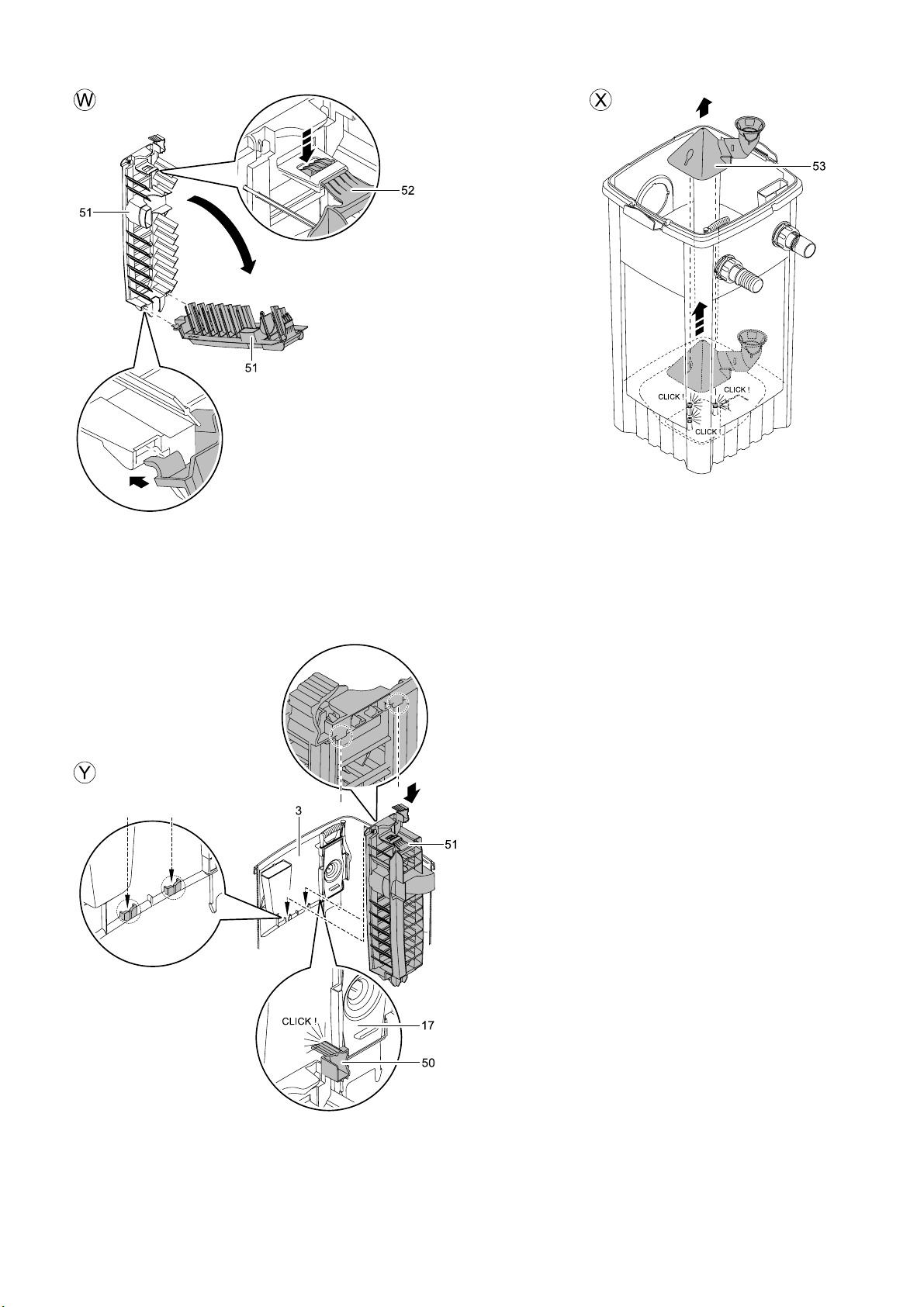
Cleaning the unit
For this purpose, remove the lamella separator (51) and the dirt pyramide (52). To this effect, completely
empty the container and remove the inner cover (47). Please refer to the chapters above.
How to remove and clean the lamella separator
1. Press down the engagement hook (50) and pull the lamella separator (51) upward and out of the the
guide on the container (3) (Figure V).
2. Press in the engagement hook (52) at the lamella separator top (51) and fold out both sections of
the lamella separator (51) (Figure W).
3. Clean both parts using clean water and a soft brush.
4. Reassemble the lamella separator (51) in the reverse order
5. Insert the lamella separator (51) in the container (3) (Figure Y).
− Ensure that the engagement hook (50) engages at the stop valve (17).
How to remove and clean the dirt pyramid (Figure X)
Only remove the dirt pyramid (53) if necessary. A great deal of force is required for disassembly and reassembly.
1. Reach beneath the dirt pyramid (53) and detach the pyramid from the three holders at the container
bottom by vigorously pulling up.
2. Clean the dirt pyramid (53) using water and a soft brush.
3. Wash out the container bottom.
4. Plug the dirt pyramid (53) onto the holders by applying a large amount of pressure.
− The engagement in the holders is audible by a click.
- GB -
An approx. 8 mm spacing is provided between the dirt pyramid (53) and the container bottom. This gap
allows the dirty water pump to pump off the dirt gathered at the container bottom. Take this spacing into
account during assembly. Do not attempt to press the dirt pyramid (53) fully down to the container
bottom by applying excessive force!
35
Page 21

- GB -
11 Wear parts
Wear part Model Ident No.
UVC CWS lamp
Quartz glass tube
Cleaning rotor
Filter cartridges
FiltoMatic CWS 7000 56112
FiltoMatic CWS 14000 56237
FiltoMatic CWS 25000 56237
FiltoMatic CWS 7000 13312
FiltoMatic CWS 14000 13332
FiltoMatic CWS 25000 13332
FiltoMatic CWS 7000 12703
FiltoMatic CWS 14000 12705
FiltoMatic CWS 25000 12705
FiltoMatic CWS 7000 50901 (1×)
FiltoMatic CWS 14000 50904 (1×)
FiltoMatic CWS 25000 50904 (2×)
12 Storage/Over-wintering
Prior to the period of frost starting, store the cleaning units dirty water pump (14), controller (15) and
UVC clarifying unit (16) in a frost-free place.
1. Thoroughly clean all components (see chapter Carry out complete cleaning) and check all
components for damage.
− The container (3) and the foam filters (49) need not be stored frost-free. However, completely
empty the container (3) prior to storing using the pump.
2. Cover the container (3) to prevent the ingress of water.
− The lid (1) being closed is not sufficient, as water can enter the container through the recess
provided for the controller.
OASE recommends the following cover:
− FiltoMatic Cap, size L, for FiltoMatic 7000 CWS and 14000 CWS (OASE Order No. 50268)
− FiltoMatic Cap, size XL, for FiltoMatic 25000 CWS (OASE Order No. 50269)
13 Disposal
Dispose of the unit in accordance with the national legal regulations.
36
Page 22

DE Technische
Daten
Anschlussspannung Leistungsaufnahme UVC-
Vorklärer
GB Technical data Connection voltage Power consumption UVC
clarifying unit
FR Caractéristiques
techniques
NL Technische
gegevens
Tension de
raccordement
Consommation Appareil
de préclarification à UVC
Aansluitspanning Stroomverbruik UVC-
voorzuiveringsapparaat
ES Datos técnicos Tensión de conexión Consumo de potencia
Preclarificador UVC
PT Dados técnicos Tensão eléctrica Consumo de energia
Aparelho de pré-
tratamento UVC
IT Caratteristiche
tecniche
Tensione di attacco Potenza assorbita
Predepuratore UVC
Pompa dell'acqua sporca
DK Tekniske data Tilslutningsspænding Strømforbrug
UVC-forrenseenhed
NO Tekniske data Nettspenning Inngangseffekt
UV-forrenser
SE Tekniska data Anslutningsspänning Effekt
UVC-förrening
FI Tekniset tiedot Liitäntä-jännite Ottoteho
UVC-esipuhdistaja
HU Műszaki adatok Csatlakoztatási
feszültség
PL Dane techniczne Napięcie
przyłączeniowe
Teljesítményfelvétel
UVC előtisztító
Pobór mocy
Osadnik wstępny z lampą
UV
CZ Technické údaje Připojovací napětí Příkon
Předčišťovač UVC
SK Technické údaje Napájacie napätie Príkon
UVBC-odkalovač
SI Tehnični
podatki
Priključna napetost Nazivna moč
UVC predčistilna naprava
HR Tehnički podaci Priključni napon Prijemna snaga
UVC-razbistrivač
RO Date tehnice Tensiune de
conexiune
Putere consumatã
Dispozitivul de pre-
limpezire cu raze
ultraviolete
BG Технически
данни
UA Технічні
характеристики
Напрежение в
точката на
свързване
Напруга мережі
живлення
Потребявана мощност
UVC-устройство за
предварителна очистка
Споживана потужність
Ультрафіолетовий
очисний пристрій
Leistungsaufnahme
Schmutzwasserpumpe
Power consumption
Dirty water pump
Consommation
Pompe à eau sale
Stroomverbruik
Afvalwaterpomp
Consumo de potencia
Bomba de agua sucia
Consumo de energia
Bomba de água suja
Potenza assorbita
Strømforbrug
Spildevandspumpe
Inngangseffekt
Spillvannspumpe
Effekt
Smutsvattenpump
Ottoteho
Likavesipumppu
Teljesítményfelvétel
Szennyvíz szivattyú
Pobór mocy
Pompa brudnej wody
Příkon
Kalové čerpadlo
Príkon
Čerpadlo znečistenej
vody
Nazivna moč
Črpalka za onesnaženo
vodo
Prijemna snaga
Crpka za prljavu vodu
Putere consumatã
Pompa de apă murdară
Потребявана мощност
Помпа за мръсна вода
Споживана потужність
Очисний насос
Leistungsaufnahme
Wassertemperatur Gewicht Länge Anschlussleitung
Steuerung
Control system power
Water temperature Weight Length of connection cable
consumption
Puissance absorbée,
commande
Vermogensopname
Température de l’eau Poids Conduite de raccordement
longue
Watertemperatuur Gewicht Lengte aansluitleiding
besturing
Consumo de potencia
del control
Consumo de energia
sistema de controlo
Potenza assorbita
comando
Strømforbrug af
styring
Temperatura del agua Peso Longitud del cable de
conexión
Temperatura de água Peso Comprimento do cabo de
alimentação
Temperatura
dell'acqua
Peso Lunghezza cavo di
collegamento
Vandtemperatur Vægt Længde på tilslutnings-
ledning
Inngangseffekt styring Vanntemperatur Vekt Lengde stikkledninger
Effektförbrukning
Vattentemperatur Vikt Längd anslutningsledning
styrning
Ottoteho ohjaus Veden lämpötila Paino Liitäntäjohdonpituus
Vezérlő
Vízhõmérséklet Súly Csatlakozóvezeték hossza
teljesítményfelvétel
Pobór mocy
sterowania
Temperatura wody Masa Długość przewodu
przyłączeniowego
Řízení příkonu Teplota vody Hmotnost Délka připojovacího vedení
Príkon riadenia Teplota vody Hmotnost’ Dĺžka prípojného vedenia
Moč krmilnega
Temperatura vode Teža Dolžina priključne vrvice
sistema
Potrošnja energije
Temperatura vode Težina Duljina priključne cijevi
upravljača
Puterea consumată de
sistemul de comandă
Консумация на
мощност управление
Споживана
Temperatura apei Greutate Lungimea cablului de
conexiune
Температурата на
водата
Тегло Дължина свързващ
проводник
Температура води Вага Довжина злучного проводу
потужність
управління
337
Page 23

RU Технические
中文 技术数据 连接电压 紫外线预净化器的消耗功
FiltoMatic
CWS 7000
FiltoMatic
CWS 14000
FiltoMatic
CWS 25000
данные
AC 230 V / 50 Hz
AC 230 V / 50 Hz
AC 230 V / 50 Hz
Напряжение
питающей сети
AC 12 V / 30 VA
AC 12 V / 30 VA
AC 12 V / 30 VA
Потребляемая
мощность
УФ-блок
предварительной
очистки
率
11 W 27 W 2.8 W +4 … +35 °C 9.2 kg 10 m
24 W 27 W 2.8 W +4 … +35 °C 10.3 kg 10 m
24 W 27 W 2.8 W +4 … +35 °C 13.4 kg 10 m
Потребляемая
мощность
Насос для откачки
грязной воды
污水泵的消耗功率 控制器的消耗功率 水温 重量 连接导线长度
Потребляемая
мощность системы
управления
Температура воды Вес Длина
подсоединительного
провода
338
Page 24

DE Technische
Daten
GB Technical
data
FR Caractéristiqu
es techniques
NL Technische
gegevens
ES Datos
técnicos
PT Dados
técnicos
IT Caratteristich
e tecniche
DK Tekniske data Dimensioner Temperatursensors
NO Tekniske data Dimensjoner Målepresisjon
SE Tekniska data Mått Mätprecision
FI Tekniset
tiedot
HU Műszaki
adatok
PL Dane
techniczne
CZ Technické
údaje
SK Technické
údaje
SI Tehnični
podatki
HR Tehnički
podaci
RO Date tehnice Dimensiuni Precizia de măsurre a
Abmessungen Messgenauigkeit
Temperaturfühler
Dimensions Measuring accuracy
of the temperature
sensor
Dimensions Précision de mesure
du thermostat
Afmetingen Meetnauwkeurigheid
temperatuursensor
Dimensiones Exactitud de medición
sensor de
temperatura
Dimensões Precisão de medição
do sensor de
temperatura
Dimensioni Precisione di
misurazione sonda
termica
målenøjagtighed
Temperaturføler
temperaturgivare
Mitoitus Mittaustarkkuus
lämpötilatunnistin
Méretek Hőmérsékletérzékelő
mérési pontossága
Wymiary Dokładność
pomiarowa czujnika
temperatury
Rozměry Přesnost měření
snímače teploty
Rozmery Presnosť merania
snímača teploty
Velikosti Merilna natančnost
temperaturnega tipala
Dimenzije Točnost mjerenja
pipka za temperaturu
senzorului de
temperatură
ohne Fischbesatz
Pond volume w/o
zonder visbestand
Damstørrelse uten
Dammvolym utan
ilman kalajoukkoa
halállomány nélkül
Pojemność stawu
Prostornina ribnika
Teichvolumen
fish population
Volume de
bassin/de l'étang
sans poissons
Vijvervolume
Volumen del
estanque sin
peces
Volume do lago
sem peixes
Volume laghetto
senza patrimonio
ittico
Dammens
volumen, uden
fiskebestand
fiskebestand
fisk
Lammen tilavuus
Tótérfogat
bez zarybienia
Objem jezírka
bez rybí obsádky
Objem záhradnej
nádrže bez
zarybnenia
brez ribjega
staleža
Obujam jezerca
bez oribljenosti
Volumul iazului
fără populaţie
piscicole
Teichvolumen
mittlerer Fischbesatz
Pond volume,
medium fish
population
Volume de bassin/de
l'étang avec quantité
moyenne de poissons
Vijvervolume
gemiddeld visbestand
Volumen del
estanque con
algunos peces
Volume do lago,
número médio de
peixes
Volume laghetto
patrimonio ittico
medio
Dammens volumen,
mellem fiskebestand
Damstørrelse middels
fiskebestand
Dammvolym med
medelstor mängd fisk
Lammen tilavuus
keski-kalajoukolla
Tótérfogat közepes
halállománnyal
Pojemność stawu ze
średnim zarybieniem
Objem jezírka
se střední velká rybí
sádkou
Objem záhradnej
nádrže s priemerným
zarybnením
Prostornina ribnika s
srednje velikim ribjim
staležem
Obujam jezerca s
osrednjom oribljenosti
Volumul iazului cu
populaţie piscicolă
medie
Teichvolumen hoher
Fischbesatz
Pond volume, high
fish population
Volume de bassin/de
l'étang avec quantité
importante de
poissons
Vijvervolume hoog
visbestand
Volumen del
estanque con muchos
peces
Volume do lago, alto
número de peixes
Volume laghetto
notevole patrimonio
ittico
Dammens volumen,
stor fiskebestand
Damstørrelse tett
fiskebestand
Dammvolym med stor
mängd fisk
Lammen tilavuus
korkealla kalajoukolla
Tótérfogat magas
halállománnyal
Pojemność stawu z
wysokim zarybieniem
Objem jezírka
s velkou rybí sádkou
Objem záhradnej
nádrže s vysokým
zarybnením
Prostornina ribnika z
velikim ribjim
staležem
Obujam jezerca s
velikom oribljenosti
Volumul iazului cu
populaţie piscicolă
ridicată
Wasseraufnahme
Behälter
Container water
volume
Volume du
récipient
Wateropname
bak
Volumen de agua
del recipiente
Capacidade do
depósito
Capacità
recipiente
Beholders
vandoptagelse
Tømme beholder Driftstrykk maks. gjenn
Vattenvolym i
behållare
Vedenotto säiliö Käyttöpaine Maks.
Tartály vízfelvétel Üzemi nyomás max.
Pobór wody
zbiornika
Napouštění
nádrže
Zásobník prítoku Prevádzkový
Posoda za vodo Delovni tlak Maks. pretok Min. pretok
Potrošnja vode u
spremniku
Capacitatea
vasului de apă
Betriebsdruck Max.
Operating
pressure
Pression de
service
Bedrijfsdruk max.
Presión de
servicio
Pressão de
serviço
Pressione
d'esercizio
Driftstryk maks.
Drifttryck Max. flöde Min. flöde
Ciśnienie
robocze
Prevádzkový
tlak
tlak
Radni tlak maks.
Presiune de
funcţionare
Durchfluss
Max. flow Min. flow
Débit
maximal
doorstroming
Paso máx. Paso mín.
Caudal
máximo
Portata max. Portata min.
gennemløb
omstrømmin
g
läpivirtaus
átáramlás
maks. natęż
enie
przepływu
max. průtok min. průtok
max. prietok min. prietok
protjecanje
Debitul max. Debitul min.
Min.
Durchfluss
Débit minimal
min.
doorstroming
Caudal
mínimo
min.
gennemløb
min. gjennom
strømming
Min.
läpivirtaus
min.
átáramlás
min. natężeni
e przepływu
min.
protjecanje
339
Page 25

BG Технически
UA Технічні
RU Технические
中文 技术数据 尺寸 温度传感器测量精度 没有鱼时的池塘容量 有中等鱼量时的池塘
FiltoMatic
CWS 7000
FiltoMatic
CWS 14000
FiltoMatic
CWS 25000
данни
характеристи
ки
данные
380 × 380
380 × 380
380 × 580
Размери Измервателна
точност
температурен
датчик
Виміри Точність виміру
датчика
температури
Измерения Точность измерения
датчика
температуры
±2 °C (+4 … +35 °C) 6 m3 3 m3 1.5 m3 20 l max. 0.6 bar 3500 l/h 2500 l/h
× 520 mm
±2 °C (+4 … +35 °C) 12 m3 6 m3 3 m3 35 l max. 0.6 bar 5000 l/h 3500 l/h
× 720 mm
±2 °C (+4 … +35 °C) 24 m3 12 m3 6 m3 65 l max. 0.6 bar 6000 l/h 5000 l/h
× 720 mm
Обем на езерото
без риби
Об'єми ставка без
риби
Объем пруда без
рыбопосадки
Обем на езерото
средно количество
риба
Об'єми ставка із
середньою кількістю
риби
Объем пруда со
средней
рыбопосадкой
容量
Обем на езерото
голямо количество
риба
Об'єми ставка з
великою кількістю
риби
Объем пруда с
большой
рыбопосадкой
有大量鱼时的池塘容
量
Консумация на
вода резервоар
Водопоглинення
резервуара
Емкость
резервуара для
воды
箱体容量 运行压力 最大流量 最小流量
Работно
налягане
Робочий тиск Максимальн
Рабочее
давление
Макс.
разход
е протікання
макс. расход мин. расход
Мин. разход
Мінімальне
протікання
340
Page 26

DE Staubdicht. Wasserdicht bis 2 m
GB Dust tight. Submersible to 2 m
FR Imperméable aux poussières.
NL Stofdicht. Waterdicht tot een diepte
ES A prueba de polvo. Impermeable al
PT À prova de pó. À prova de água até
IT A tenuta di polvere. Impermeabile
DK Støvtæt. Vandtæt ned til 2 m
NO Støvtett. Vanntett ned til
SE Dammtät. Vattentät till
FI Pölytiivis. Vesitiivis 2 m syvyyteen
HU Portömített. Vízálló 2 m-es
PL Pyłoszczelny. Wodoszczelny do
CZ Prachotěsný. Vodotěsný do
SK Prachotesný. Vodotesný do hĺbky
SI Ne prepušča prahu. Ne prepušča
HR Ne propušta prašinu. Ne propušta
RO Etanş la praf. Etanş la apă, până la
BG Защитено от прах. Водоустойчив
UA Пилонепроникний.
RU Пыленепрониц. Водонепрониц.
CN
Tiefe.
depth.
Etanche à l'eau jusqu'à une
profondeur de 2 m.
van 2 m.
agua hasta 2 m de profundidad.
2 m de profundidade.
all'acqua fino a 2 m di profondità.
dybde.
2 m dyp.
2 m djup.
asti
mélységig.
2 m głębokości.
hloubky 2 m.
2 m.
vode do globinen 2 m.
vodu do 2 m dubine.
o adâncime de 2 m.
до дълбочина 2 м.
Водонепроникний до 2 м.
на глубине до 2 м.
防尘。至 2 米深防水。 注意!
Achtung!
Gefährliche UVC-Strahlung!
Attention!
Dangerous UVC radiation!
Attention !
Rayonnement UVC dangereux !
Let op!
Gevaarlijke UVC-straling!
¡Atención!
Radiación UVC peligrosa.
Atenção!
Radiação UVC perigosa!
Attenzione!
Pericolosa radiazione UVC!
Fare!
Farlig UVC-stråling!
NB!
Farlig UV-stråling!
Varning!
Farlig UVC-strålning!
Huomio!
Vaarallinen UVC-säteily!
Figyelem!
Veszélyes UVC-sugárzás!
Uwaga!
Niebezpieczne promieniowanie
ultrafioletowe!
Pozor!
Nebezpečné ultrafialové záření.
Pozor!
Nebezpečné ultrafialové žiarenie.
Pozor!
Nevarno UVC-sevanje!
Pažnja!
Opasno UVC zračenje!
Atenţie!
Radiaţii ultraviolete periculoase!
Внимание!
Опасно ултравиолетово лъчение!
Увага!
Небезпечне ультрафіолетове
випромінювання!
Внимание!
Опасное коротковолновое
УФ-излучение!
危险的紫外线照射!
Vor direkter Sonneneinstrahlung
schützen
Protect from direct sun radiation. Remove the unit at temperatures
Protéger contre les rayons directs
du soleil.
Beschermen tegen direct zonlicht. Bij vorst moet het apparaat
Protéjase contra la radiación
directa del sol.
Proteger contra radiação solar
directa.
Proteggere contro i raggi solari
diretti.
Beskyt mod direkte sollys. Afinstaller enheden ved frostvejr! Må ikke bortskaffes med det
Beskytt mot direkte sollys. Demonter apparatet ved frost! Ikke kast i alminnelig
Skydda mot direkt solstrålning. Demontera apparaten innan första
Suojattava suoralta
auringonvalolta.
Óvja közvetlen napsugárzástól. Fagy esetén a készüléket szerelje
Chronić przed bezpośrednim
nasłonecznieniem.
Chránit před přímým slunečním
zářením.
Chránit’ pred priamym slnečným
žiarením.
Zaščitite pred neposrednimi
sončnimi žarki.
Zaštitite od izravnog sunčevog
zračenja.
Protejaţi împotriva razelor directe
ale soarelui.
Да се пази от слънчеви лъчи. При опасност от измръзване
Пристрій повинен бути
захищений від прямого
сонячного випромінювання.
Защищать от прямого
воздействия солнечных лучей.
防止阳光直射。
Bei Frost das Gerät deinstallieren! Nicht mit normalem Hausmüll
below zero (centigrade)!.
Retirer l’appareil en cas de gel ! Ne pas recycler dans les ordures
gedeïnstalleerd worden!
Desinstale el equipo en caso de
heladas.
Em caso de geada, desinstalar o
aparelho!
In caso di gelo disinstallare
l'apparecchio!
frosten!
Laite on purettava ennen pakkasta. Älä hävitä laitetta tavallisen
le!
W razie mrozu zdeinstalować
urządzenie!
Při mrazu přístroj odinstalovat! Nelikvidovat v normálním
Pri mraze prístroj odinštalovať! Nelikvidovať v normálnom
Ob zmrzali demontirajte aparat! Ne zavrzite skupaj z
U slučaju mraza deinstalirajte
uređaj!
La îngheţ dezinstalaţi aparatul ! Nu aruncaţi în gunoiul menajer ! Atenţie !
деинсталирайте уреда!
Перед морозами пристрій
необхідно демонтувати
При наступлении морозов прибор
демонтировать!
在霜冻时
拆卸设备!
entsorgen!
Do not dispose of together with
household waste!
ménagères !
Niet bij het normale huisvuil doen! Let op!
¡No deseche el equipo en la
basura doméstica!
Não deitar ao lixo doméstico! Atenção!
Non smaltire con normali rifiuti
domestici!
almindelige husholdningsaffald.
husholdningsavfall!
Får inte kastas i hushållssoporna! Varning!
talousjätteen kanssa!
A készüléket nem a normál
háztartási szeméttel együtt kell
megsemmisíteni!
Nie wyrzucać wraz ze śmieciami
domowymi!
komunálním odpadu!
komunálnom odpade!
gospodinjskimi odpadki!
Nemojte ga bacati u običan kućni
otpad!
Не изхвърляйте заедно с
обикновения домакински боклук!
Не викидайте разом із
побутовим сміттям!
Не утилизировать вместе с
домашним мусором!
不要与普通的家庭垃圾一起丢弃! 注意!
Achtung!
Lesen Sie die Gebrauchsanleitung
Attention!
Read the operating instructions
Attention !
Lire la notice d'emploi
Lees de gebruiksaanwijzing
¡Atención!
Lea las instrucciones de uso
Leia as instruções de utilização
Attenzione!
Leggete le istruzioni d'uso!
OBS!
Læs brugsanvisningen
NB!
Les bruksanvisningen
Läs igenom bruksanvisningen
Huomio!
Lue käyttöohje
Figyelem!
Olvassa el a használati útmutatót
Uwaga!
Przeczytać instrukcję użytkowania!
Pozor!
Přečtěte Návod k použití!
Pozor!
Prečítajte si Návod na použitie
Pozor!
Preberite navodila za uporabo!
Pažnja!
Pročitajte upute za upotrebu!
Citiţi instrucţiunile de utilizare !
Внимание!
Прочетете упътването
Увага!
Читайте інструкцію.
Внимание!
Прочитайте инструкцию по
использованию
请阅读使用说明书。
341
Page 27

342
Page 28

343
Page 29

344
Page 30

OASE GmbH · www.oase-livingwater.com
Tecklenburger Straße 161 · 48477 Hörstel · Germany
17901/02-14
 Loading...