

Page 1

1
Gebrauchsanweisung
Directions for use
Mode d’emploi
Gebruiksaanwijzing
T 305 844 372 01A/ID.24828/03K
3.000
6.000
11.000
Filtoclear
Page 2

2
Inhalt Deutsch Seite
Symbole 3-4
Auspacken/Lieferumfang/Bestimmungsgemäße Verwendung 4
Sicherheitshinweise 5-7
Funktionsweise des Druckfilters Filtoclear 7-8
Installationshinweise zur Klarwassergarantie 9-10
Druckfilter Filtoclear aufstellen und montieren 10-12
Druckfilter in Betrieb nehmen 12
Reinigung und Wartung vom Filtoclear 13-15
Quarzglasrohr reinigen 15-16
UVC-Lampe austauschen 16
Lagerung/Überwinterung/Entsorgungshinweis/Reparatur/Kabeltausch 17
Störungsbehebung 17-18
Technische Daten 18
Verschleißteile 19
Geräteübersicht 19-21
Garantie 22
Contenu Français Page
Symboles 43-44
Déballage/Fournitures/Domaines d’applications 44
Consignes de sécurité 45-47
Mode de fonctionnement du filtre pression Filtoclear 47-48
Consignes d’installation en rapport avec la garantie d’eau claire 49-50
Installer et monter le filtre pression Filtoclear 50-51
Mettre en service le filtre pression 52
Nettoyage et entretien du Filtoclear 52-55
Nettoyer tube en verre minéral 55
Echange de la lampe UVC 55-56
Entreposage hivernal/Consigne d’élimination des déchets 56
Réparation/Echange des câbles 57
Remèdes aux anomalies 57-58
Caractéristiques techniques/Pièces d’usure 58
Aperçu des appareils 59-61
Garantie 62
Contents English Page
Symbols 23-24
Unpacking/Parts supplied/Appropriate use 24
Safety guidelines 25-26
How the Filtoclear pressure filters works 27-28
Installation guidelines with regard to the clear water guarantee 28-30
Installing and connecting the Filtoclear pressure filter 30-31
Starting up the pressure filter 32
Cleaning and maintenance of the Filtoclear 32-34
Cleaning the quartz tube 35
Replace UVC-lamp 35-36
Storage/winter storage/Advice in disposal/Repair/cable replacement 36
Troubleshooting 37
Technical Data/Wearing parts 38
Product overview 39-41
Guarantee 42
Inhoud Nederlands Pagina
Symbolen 63-64
Uitpakken/Omvang van de levering/Doelmatig gebruik 64
Veiligheidsinstructies 65-66
Werkwijze van de drukfilter Filtoclear 67-68
Installatie-instructies bij de helderwatergarantie 68-69
Drukfilter Filtoclear opstellen en monteren 70-71
Drukfilter in gebruik nemen 72
Reiniging en onderhoud van de Filtoclear 72-73
Reinigen van de filterschuimen door uitwassen 73-75
UVC-lamp vervangen 75-76
Opslag/Overwintering/Verwerkingsinstructie/Reparatie/Kabelvervanging 76
Opheffen van storingen 77
Technische gegevens/Slijtageonderdelen 78
Overzicht van het apparaat 79-81
Garantie 82
Page 3
3
Vor der ersten Benutzung machen Sie sich mit Hilfe dieser
Gebrauchsanweisung mit dem Gerät vertraut. Beachten Sie
unbedingt die Sicherheitshinweise für den richtigen und sicheren
Gebrauch.
Aus Sicherheitsgründen dürfen Kinder und Jugendliche unter 16
Jahren, sowie Personen, die mögliche Gefahren nicht erkennen
können oder die nicht mit dieser Gebrauchsanweisung vertraut
sind, dieses Gerät nicht benutzen!
Bitte bewahren Sie diese Gebrauchsanweisung sorgfältig auf! Bei
Besitzerwechsel geben Sie bitte die Gebrauchsanweisung mit
dem Produkt weiter.
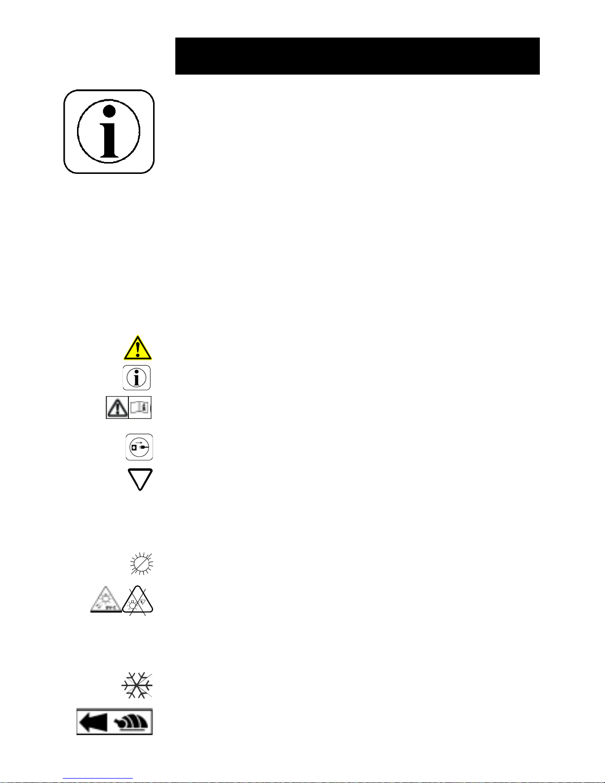
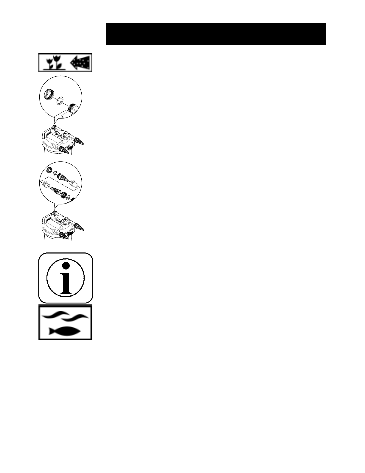
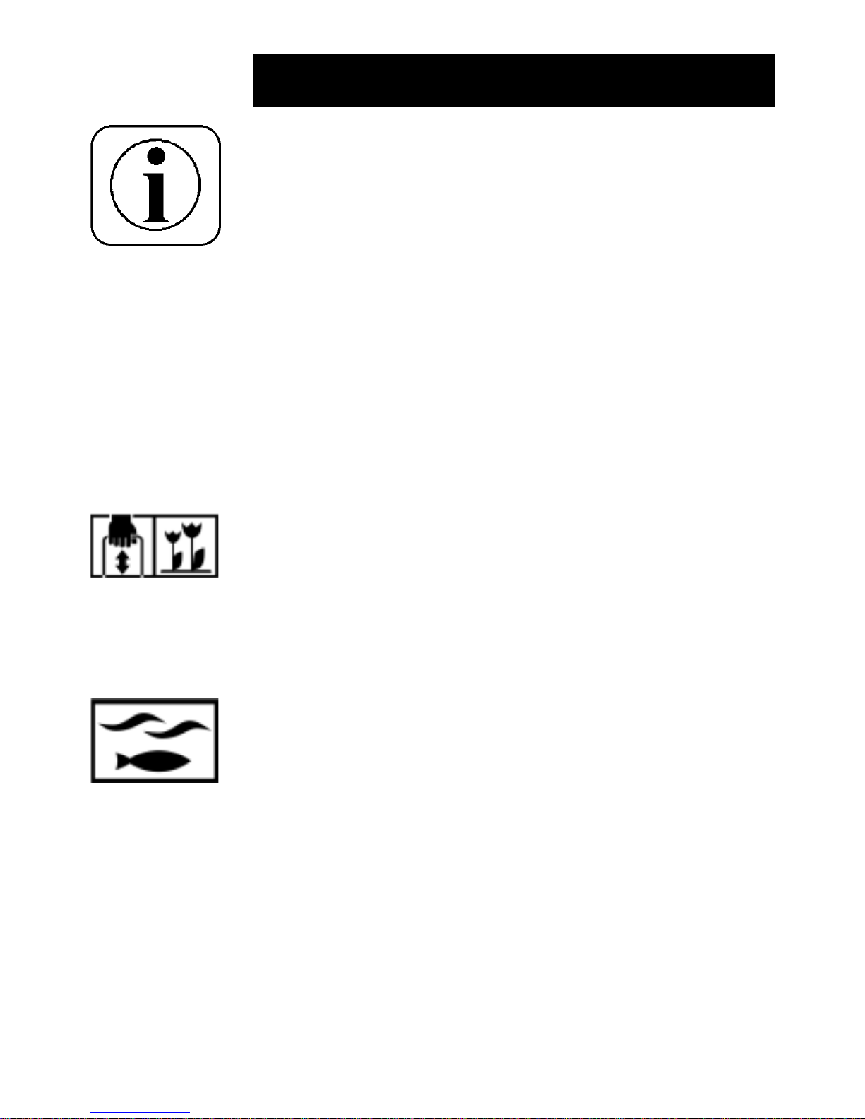
Symbole
Die auf dem Gerät und in dieser Gebrauchsanweisung verwendeten Symbole haben folgende Bedeutung:
Achtung! Wichtiger Hinweis auf Gefahren!
Wichtige Information!
Achtung! Lesen Sie die Gebrauchsanweisung!
Achtung! Ziehen Sie den Netzstecker!
Leuchte ist geeignet zur direkten Befestigung auf normal entflammbaren Befestigungsflächen.
Schutz gegen das Berühren von gefährlichen Teilen mit dem
Finger und Schutz gegen das Eindringen von Spritzwasser.
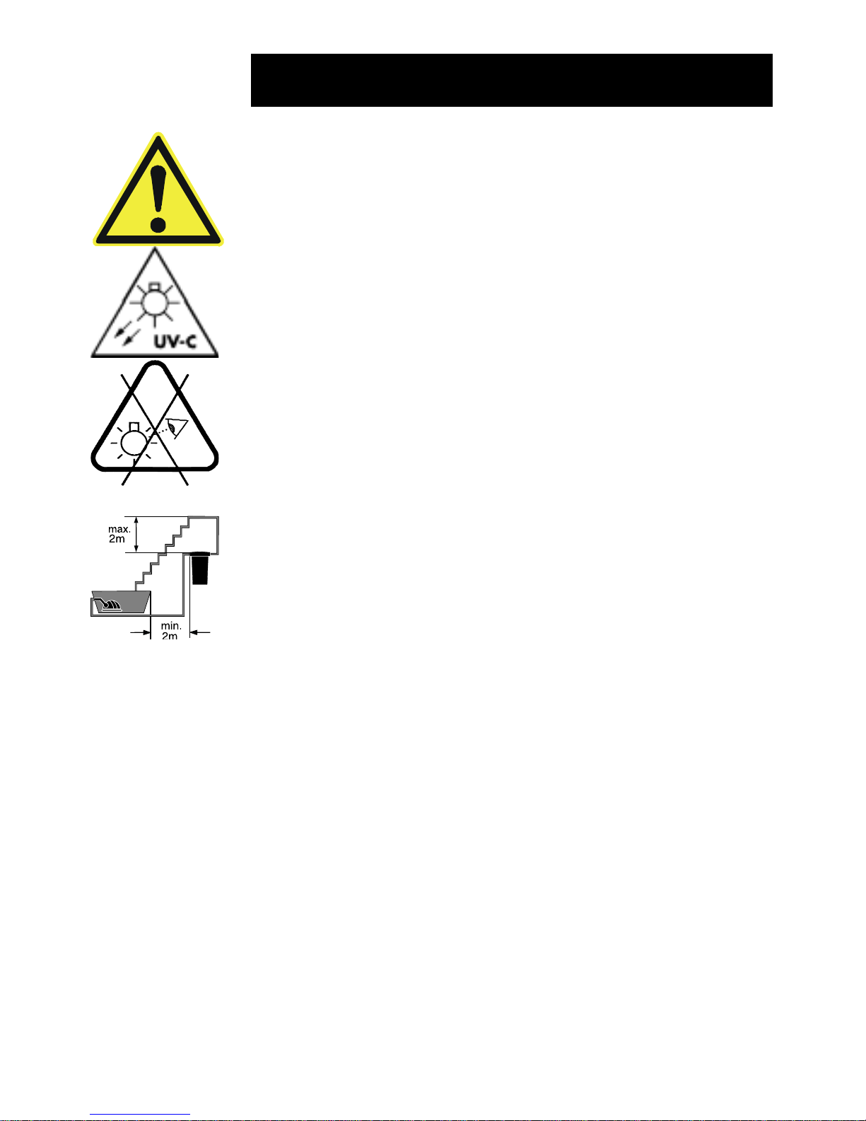
Vor direkter Sonneneinstrahlung schützen!
Achtung! Gefährliche UVC - Strahlen!
Der Filtoclear darf maximal mit einem Druck von 0,2 bar betrieben
werden!
Bei zu erwartenden Frost müssen Sie den Filtoclear deinstallieren!
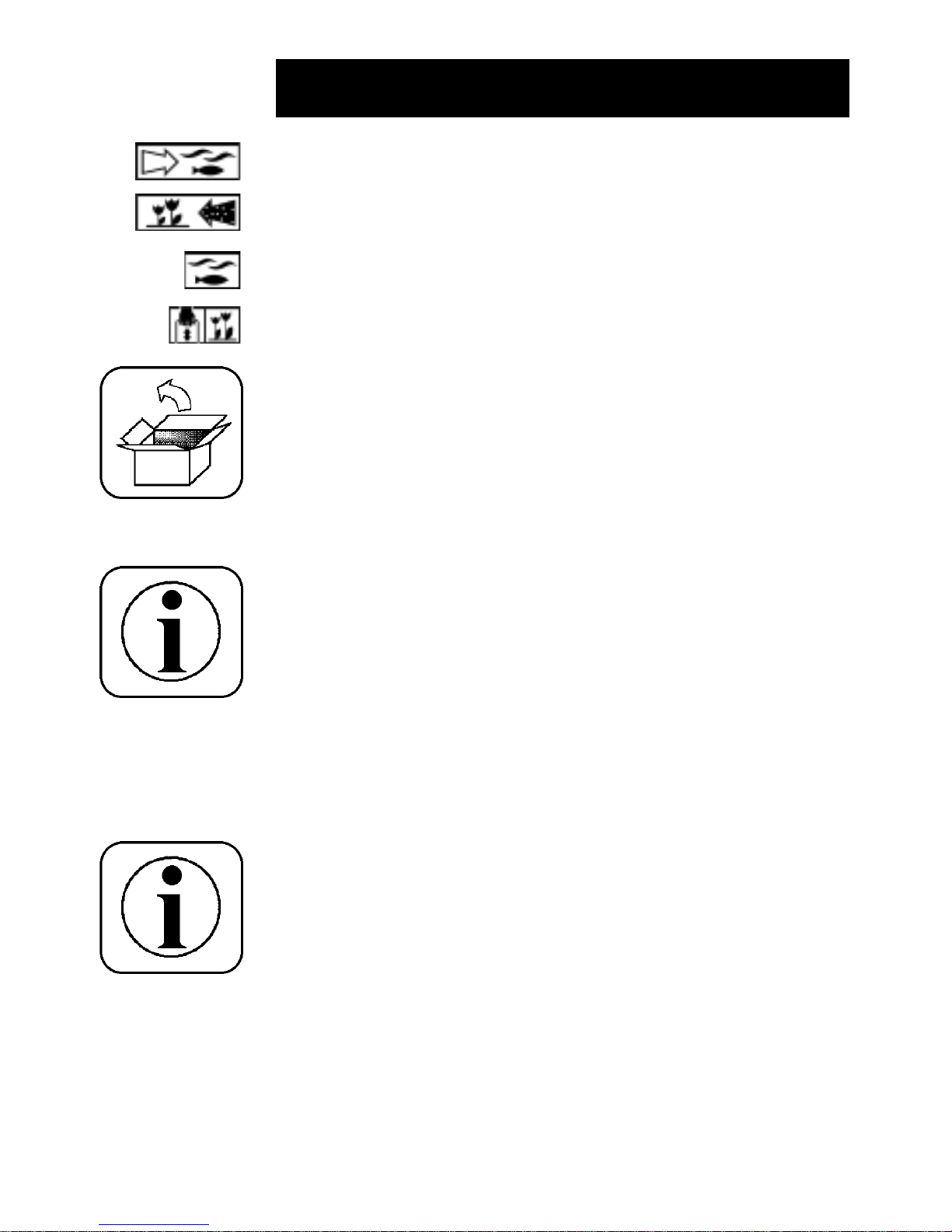
Wassereinlauf von der Pumpe in den Filter.
IP
24
Gebrauchsanweisung
F
P
max
= 0,2 bar
Page 4
4
Auspacken
Sind beim Auspacken äußere Schäden sichtbar, die betriebswichtige Teile in ihrer Funktion beeinträchtigen können, melden
Sie die festgestellten Mängel noch am gleichen Tag dem
Anlieferer und bestehen Sie auf eine schriftliche Tatbestandsaufnahme. Als nächstes setzen Sie sich mit der Lieferfirma in
Verbindung, die dann alles Weitere veranlassen wird.
Wasserauslass von dem Filter in den Teich.
Reinigungsanschluss von dem Filter z.B. in die Kanalisation oder
in das Blumenbeet.
Funktionsschalterstellung „Filtern“.
Funktionsschalterstellung „Reinigen“.
Lieferumfang
1 x Druckfilter Filtoclear mit integriertem UVC
2 x Stufenschlauchspiraltülle1½“, transparent
1 x Stufenschlauchspiraltülle 1½“, schwarz
1 x Stufenschlauchspiraltülle 1½“, mit Gewinde, schwarz
3 x Überwurfmuttern 1½“
2 x Durchflussfahne
1 x Flachdichtung
1 x Gebrauchsanweisung
1 x Garantiekarte Filtoclear
Bestimmungsgemäße Verwendung
Der Filtoclear mit integriertem UVC ist ein geschlossenes Druckfiltersystem für die biologische und mechanische Filterung von
normalem Teichwasser von +4°C bis + 35°C. Dieser Druckfilter
Filtoclear ist ausschließlich für den privaten Einsatz zur Reinigung
von Gartenteichen mit oder ohne Fischbesatz vorgesehen.
In Kombination mit den OASE-Teichpumpen Aquamax wird eine
optimale Reinigung erzielt.
Gebrauchsanweisung
Page 5
5
P
max
= 0,2 bar
Sicherheitshinweise
Druckfilter Filtoclear mit integriertem UVC
- Achtung: Gefährliche ultraviolette Strahlung. Die Strah-
lung der UVC-Lampe ist gefährlich für Augen und Haut!
Betreiben Sie die Lampe des Filtoclear-UVC niemals außer-
halb des Gehäuses!
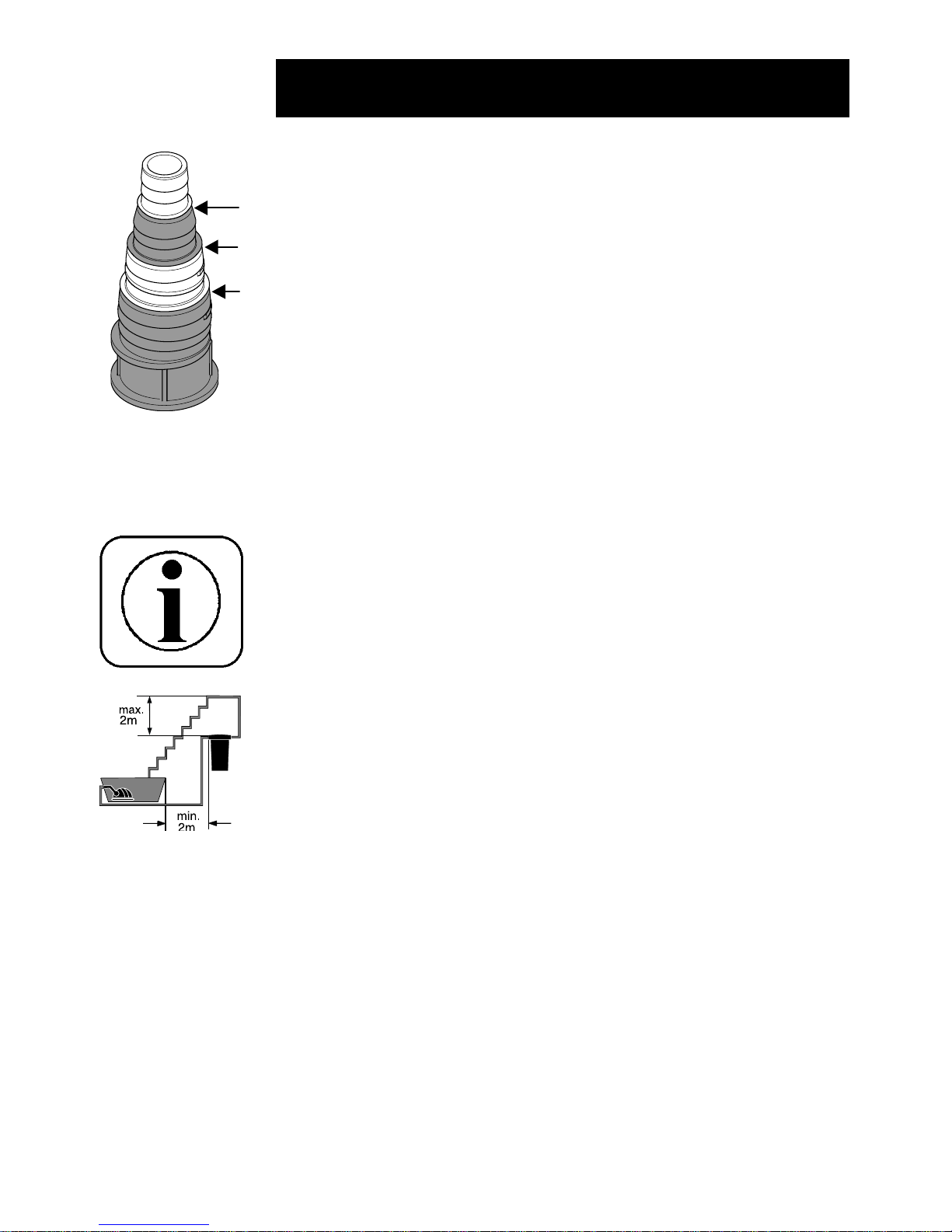
- Stellen Sie den Filtoclear mit integriertem UVC überflutungssicher auf. Schützen Sie Ihren Filtoclear gegen das Hineinfallen
in den Teich. Halten Sie dabei einen Abstand zum Teichrand
von mindestens 2m ein.
- Schalten Sie immer erst die Pumpe ein, bevor Sie den
Filtoclear–UVC in Betrieb nehmen. Die UVC-Lampe darf nicht
ohne Wasserdurchfluss betrieben werden.
- Betreiben Sie den Filtoclear-UVC nicht, wenn das Anschlusskabel,
die UVC-Lampe oder das Gehäuse defekt erscheinen!
- Betreiben Sie den Filtoclear-UVC nicht, wenn sich Personen
im Wasser aufhalten!
- Achtung: Beim Filtoclear-UVC schaltet der eingebaute
Temperaturwächter die UVC-Lampe bei Überhitzung automatisch aus. Nach Abkühlung wird die UVC-Lampe automatisch
wieder eingeschaltet.
- Öffnen Sie niemals das Gehäuse des Filtoclear-UVC oder
deren zugehörigen Teile, wenn nicht ausdrücklich in der
Gebrauchsanweisung darauf hingewiesen wird.
- Vergleichen Sie die elektrischen Daten des Versorgungsnetzes mit denen des Typenschildes. Diese Daten müssen
übereinstimmen.
- Stellen Sie sicher, dass der Filtoclear-UVC über eine Fehler-
strom-Schutzeinrichtung (FI, bzw. RCD) mit einem
Bemessungs-Fehlerstrom von nicht mehr als 30mA versorgt ist.
- Ziehen sie immer den Netzstecker aller im Wasser befindlichen Geräte und vom Filtoclear-UVC, bevor Sie Arbeiten am
Filtoclear durchführen!
- Bei Fragen und Problemen des elektrischen Anschlusses
wenden Sie sich zu Ihrer eigenen Sicherheit an einen Elektro-
fachmann!
- Tauchen Sie das Gerät niemals unter Wasser!
- Betreiben Sie den Filtoclear-UVC nur an einer Steckdose mit
Schutzkontakt. Diese muss nach den jeweils gültigen nationalen Vorschriften (VDE, EN...) errichtet sein. Stellen Sie
sicher, daß der Schutzleiter durchgehend bis zum Filtoclear-
UVC geführt wird.
Gebrauchsanweisung
Page 6
6
Gebrauchsanweisung
- Verwenden Sie niemals Installationen, Adapter, Verlängerungs-
oder Anschlußleitungen ohne Schutzkontakt.
- Netzanschlussleitungen dürfen keinen geringeren Querschnitt
haben als Gummischlauchleitung mit dem Kurzzeichen HO5
RNF. Verlängerungsleitungen müssen der DIN VDE 0620
genügen.
- Elektrische Installationen an Gartenteich und Schwimmbekken müssen den internationalen und nationalen
Errichterbestimmungen entsprechen.
- Halten Sie die Anschlussstellen trocken!
- Tragen oder ziehen Sie den Filtoclear nicht am Anschlusskabel!
Schützen Sie das Anschlusskabel vor Hitze, Öl und scharfen
Kanten.
- Verlegen Sie die Schläuche und die Anschlussleitung so, dass
sie kein Hindernis darstellen und Beschädigungen ausgeschlossen sind!
- Achtung! Unfallgefahr! Betreiben Sie den Druckfilter Filtoclear
mit integriertem UVC niemals mit mehr als 0,2 bar (2mWS)
Wasserdruck! Somit darf der Höhenunterschied zwischen
Filterdeckel und druckloser Auslaufstelle max. 2m betragen.
Der maximale Förderdruck der eingesetzten Pumpe darf 0,5
bar (5mWS) nicht überschreiten.
- Betreiben Sie den Filtoclear nur mit Druckschläuchen, welche
mindestens für 0,2 bar bzw. den maximalen Druck der Pumpe
zugelassen sind.
- Kontrollieren und reinigen Sie den Wasserablauf zum Teich
regelmäßig. Der Ablauf sollte stets frei sein, da der Filter bei
Verstopfung mit einem höherem Betriebsdruck als 0,2 bar
betrieben würde. Dadurch besteht die Gefahr einer Undichtigkeit und somit der vollständigen Teichentleerung.
- Wichtig: Im Filterbetrieb des Filtoclear muss der
Reinigungsanschluss oder ein darauf angeschlossener Ablaufschlauch immer mit der Verschlusskappe und eingelegter
Flachdichtung verschlossen werden, um eine Entleerung des
Teiches zu verhindern. Gleichzeitig dient die Verschlusskappe
als Sicherung, falls der Funktionsschalter ungewollt auf „Reinigen“ verstellt wird.
- Stellen Sie sicher, das der Funktionsschalter bei Betrieb der
Pumpe immer auf „Filtern“ steht. Nur bei der Reinigung der
Filterschäume per Grifffunktion darf der Funktionsschalter auf
„Reinigen“ stehen.
P
max
= 0,2 bar
Page 7
7
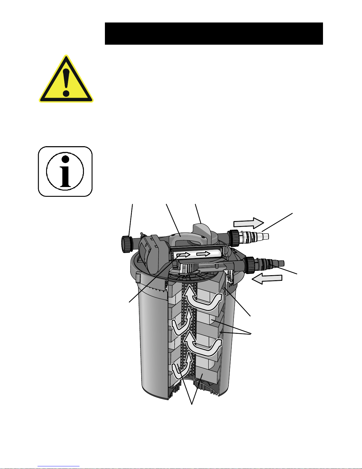
Funktionsweise des Druckfilters Filtoclear
Der Druckfilter Filtoclear mit integriertem UVC ist ein geschlossenes Filtersystem zur biologischen und mechanischen Reinigung
von Teichwasser.
Gebrauchsanweisung
- Kontrollieren Sie vor der Inbetriebnahme den korrekten Sitz der
angeschlossenen Schläuche, der Verschlusskappe und des
Spannrings mit Sicherheitsriegel.
- Fördern Sie niemals andere Flüssigkeiten als Wasser!
- Bei zu erwartenden Frost müssen Sie den Filtoclear mit
integriertem UVC deinstallieren.
- Stellen Sie den Filtoclear so auf, dass er nicht der direkten
Sonneneinstrahlung ausgesetzt ist.
- Bitte beachten Sie die örtlichen Lärmschutzbestimmungen.
A Wassereinlauf
Die Teichpumpe wird mit einem Druckschlauch an den Wassereinlauf angeschlossen.
GIH
F
A
C
D
E
B
Page 8

8
Gebrauchsanweisung
B Vorklärung des Teichwassers
Das einströmende Wasser wird unter der UVC-Lampe kurzwelliger ultravioletter Strahlung ausgesetzt. Dabei werden
Keime und Bakterien abgetötet und es findet eine Verklumpung
von Algen und damit eine Reduzierung des Algenwachstums
statt. Anschließend strömt das Wasser vom Rand her kreisförmig in den Filter.
C Vortex-System (Absetzzone)
Schwebstoffe und Bioschlamm werden durch die Zentrifugalwirkung und Schwerkraft abgeschieden.
D Mechanische Filterung
Schmutzpartikel werden von der äußeren Oberfläche der Filterschäume zurückgehalten, bevor das Wasser über die gesamte
Filterhöhe vom Rand her in den Innenbereich des Filters strömt.
E Biologische Klärung
Die Poren der Filterschäume bilden eine große innere Oberfläche, welche der Siedlungsraum für Mikroorganismen ist. Die
roten und blauen Filterschäume unterscheiden sich im Umfang
und in der Dichte. Dadurch entstehen Zonen in denen das
Wasser unterschiedlich schnell fließen kann. In Zonen mit
hoher Strömungsgeschwindigkeit (blaue Filterschäume) wird
die Besiedlung von Mikroorganismen begünstigt, die eine
Umsetzung von Ammonium über Nitrid zu Nitrat (Nitrifikation)
gewährleisten. In Zonen mit niedriger Strömungsgeschwindigkeit (rote Filterschäume) wird die Besiedlung von anaeroben
Mikroorganismen unterstützt, die eine Reduzierung von Nitrat
zu Stickstoff (Denitrifikation) vornehmen.
F Wasserauslass mit Durchflussanzeige
Am Wasserauslass wird das geklärte Wasser z.B. über einem
Druckschlauch bzw. Bachlauf in den Gartenteich zurückgeführt.
G Reinigungsanschluss
Zum Reinigen des Filters kann am Reinigungsanschluss ein
Ablaufschlauch angeschlossen werden, der beim Reinigen
des Filters das verschmutzte Wasser in die Kanalisation oder
ins Blumenbeet ableitet.
H Funktionsschalter
Der Funktionsschalter dient zum Umschalten zwischen normalem Wasserauslass zum Teich („Filtern“) und dem
Reinigungsanschluss („Reinigen“).
I Reinigung der Filterschäume per Grifffunktion
Die Filterschäume lassen sich im Betrieb vom Filtoclear durch
kräftiges „Pumpen“ am Reinigungsgriff säubern.
Page 9
9
Das Filtersystem mit integriertem UVC muss permanent 24
Stunden im Betrieb sein.
Die UVC-Lampe muss nach 8000 Betriebstunden erneuert werden, um die optimale Leistungsfähigkeit des Filtoclear-UVC zu
erhalten.
Das Filtersystem muss regelmäßig gereinigt werden.
Druckverluste durch Förderhöhe
Die Auswahltabelle berücksichtigt einen maximalen Höhenunterschied von 1 m zwischen Wasseroberfläche und dem höchsten
Punkt des Filterungssystems. Bei einem Höhenunterschied größer 1 m, ist eine entsprechend stärkere Pumpe zu verwenden.
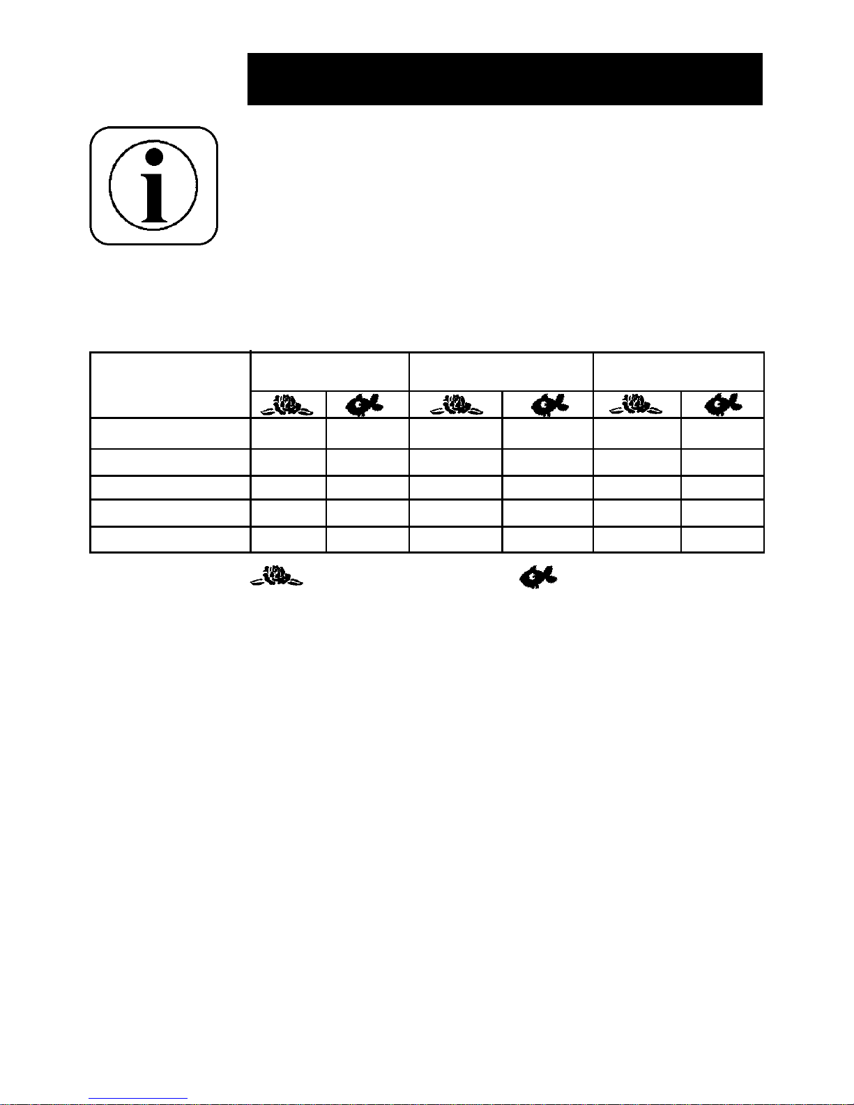
Installationshinweise zur Klarwassergarantie
Um Ansprüche aus der Klarwassergarantie geltend zu machen,
müssen folgende Installationshinweise berücksichtigt werden.
Definition Klarwasser:
Klares Wasser ist erreicht, wenn in einer Tiefe von 1 m die Fische
oder Steine am Bodengrund zu erkennen sind.
Auswahl des richtigen Systems
Filtersystem bitte nach folgender Tabelle auswählen (Auswahlkriterien: Teichgröße und ohne/mit Fischbesatz).
Filtoclear 3.000 Filtoclear 6.000 Filtoclear 11.000
Aquamax 2.000 1.500 l 750 l - - - Aquamax 3.500 2.500 l 1.250 l 3.000 l 1.500 l - Aquamax 5.500 3.000 l 1.500 l 4.000 l 2.000 l 6.000 l 3.000 l
Aquamax 10.000 - - 6.000 l 3.000 l 8.000 l 4.000 l
Aquamax15.000 - - - - 11.000 l 5.500 l
Leichte Teichverschmutzung
ohne Fischbesatz
Starke Teichverschmutzung
mit Fischbesatz
Gebrauchsanweisung
Page 10
10
Druckfilter Filtoclear aufstellen und montieren
Aufstellen des Druckfilters Filtoclear
Wählen Sie einen geeigneten Standort für den Druckfilter. Beachten Sie dabei die Installationshinweise zur Klarwassergarantie
und folgende Hinweise:
– Stellen Sie den Druckfilter Filtoclear mit integriertem UVC
überflutungssicher auf. Schützen Sie Ihren Filtoclear gegen
das Hineinfallen in den Teich. Halten Sie dabei einen Abstand
zum Teichrand von mindestens 2 m ein.
– Stellen Sie den Filter auf einem festen und ebenen Untergrund,
z.B. auf einer Terrassenfliese. Der Filter kann auch bis zur
Stufe am Behälter eingegraben werden.
– Achten Sie bitte auf einen ungehinderten Zugang zum Deckel,
um Arbeiten am Filter z.B. Reinigen der Filterschäume durchführen zu können.
– Betreiben Sie den Druckfilter Filtoclear mit integriertem UVC
niemals mit mehr als 0,2 bar (2mWS) Wasserdruck. Somit
darf der Höhenunterschied zwischen Deckel und druckloser
Auslaufstelle max. 2m betragen.
Gebrauchsanweisung
Druckverluste durch Schläuche
Verwenden Sie möglichst große Schläuche, um die Druckverluste
zu minimieren. Bei Schlauchlängen von bis zu 4 m verwenden Sie
bitte folgende Schlauchdurchmesser:
Filtoclear 3000 1 – 1¼ Zoll
Filtoclear 6000 1 – 1½ Zoll
Filtoclear 11.000 1¼ - 1½ Zoll
Bei Schlauchlängen von über 4 Metern verwenden Sie bitte
grundsätzlich Schläuche die dem oberen Wert der Skalierung
entsprechen.
Um Druckverluste zu vermeiden, sägen Sie die Stufenschlauchspiraltülle an den entsprechenden Stellen für die jeweiligen
Schläuche ab.
Vermeiden Sie unnötige Winkel und Bögen, die zu weiteren
Druckverlusten führen.
1''
1 ¼''
1 ½''
¾“
P
max
= 0,2 bar
Page 11
11
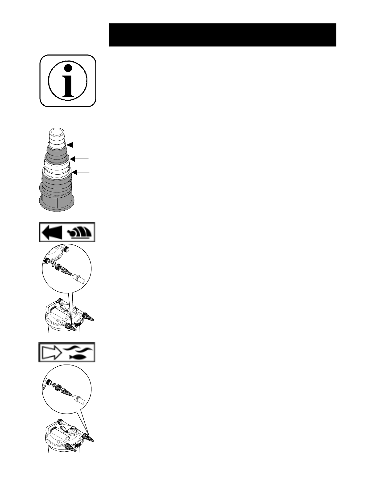
Montage am Wasserauslass
Schieben Sie die Überwurfmutter über die transparente Stufen-
schlauchspiraltülle. Den Schlauch aufschieben bzw. aufdrehen
und mit einer Schlauchklemme sichern. Die grüne Durchflussfahne
in die Überwurfmutter einlegen und fest auf dem Wasserauslassstutzen aufschrauben.
Hinweis: Wir empfehlen Ihnen, den Rücklauf nicht direkt in den
Teich zu leiten, sondern das gereinigte Wasser indirekt, z.B. über
einen kleinen Bachlauf einzuleiten. Dadurch reichert sich das
Wasser zusätzlich mit Sauerstoff an.
Gebrauchsanweisung
Montage am Wassereinlauf
Schieben Sie die Überwurfmutter über die schwarze Stufenschlauchspiraltülle. Den Schlauch aufschieben bzw. aufdrehen
und mit einer Schlauchklemme sichern.
Die Flachdichtung in die Überwurfmutter einlegen und fest auf den
Wassereinlaufstutzen aufschrauben.
1''
1 ¼''
1 ½''
¾“
Schlauchanschlüsse montieren
Stellen Sie fest, welchen Schlauchdurchmesser Sie in Abhängigkeit von der Auswahltabelle und der Schlauchempfehlung laut den
Installationshinweisen zur Klarwassergarantie benötigen (Seite 8
und 9).Betreiben Sie den Filtoclear nur mit Druckschläuchen,
welche mindestens für 0,2 bar bzw. den maximalen Druck der
Pumpe zugelassen sind. Aus dem OASE- Lieferprogramm empfehlen wir den Spiralschlauch grün mit der entsprechenden
Schlauchklemme.
Hinweis: Wir empfehlen den Schlauch mit heißen Wasser zu
erwärmen, auf die Stufenschlauchspiraltülle aufzuschieben bzw.
aufzudrehen und mit einer Schlauchklemme zu sichern. Dadurch
wird die Dichtigkeit am Anschluß erhöht.
Wichtig!: Um Druckverluste zu vermeiden sägen Sie die Stufenschlauchspiraltülle an den entsprechenden Stellen für die jeweiligen
Schläuche ab (siehe Bild).
Page 12
12
Druckfilter in Betrieb nehmen
Wichtig! Vor jeder Inbetriebnahme ist der korrekte Sitz der
angeschlossen Schläuche, der Verschlusskappe und des Spannrings mit Sicherheitsriegel zu kontrollieren. Der Funktionsschalter
muss auf dem Symbol „Filtern“ stehen. Lesen und beachten Sie
unbedingt die Sicherheitshinweise vor der Inbetriebnahme.
1. Zuerst Pumpe einschalten
Achtung! Die UVC-Lampe darf nicht ohne Wasserdurchfluss
betrieben werden.
2. Nach Inbetriebnahme der Pumpe, kontrollieren Sie sämtliche
Anschlüsse auf Dichtheit. Bessern Sie die undichten Stellen nach.
3. Netzstecker vom Filtoclear-UVC einstecken. Kontrolllampe
leuchtet mit einem blauen Lichtschimmer.
Hinweis: Bei einer Neuinstallierung erreicht der Druckfilter
seine vollständige biologische Reinigungswirkung erst nach
einigen Wochen. Eine umfangreiche Bakterientätigkeit ergibt sich erst ab einer Einsatztemperatur von + 10°C.
Gebrauchsanweisung
Montage am Reinigungsanschluss
Am Reinigungsanschluss können Sie dauerhaft einen Ablaufschlauch anschließen. So können Sie das verschmutzte Wasser
direkt z.B. in die Kanalisation oder in ein Blumenbeet leiten.
Wichtig!: Im Filterbetrieb des Filtoclear muss der Reinigungsanschluss oder ein darauf angeschlossener Ablaufschlauch immer
mit der Verschlusskappe und eingelegter Flachdichtung verschlossen werden, um ein Entleeren des Teiches zu verhindern.
Gleichzeitig dient die Verschlusskappe als Sicherung falls der
Funktionsschalter ungewollt auf „Reinigen“ verstellt wird.
Um den Ablaufschlauch zu montieren schieben Sie die Überwurfmutter über die transparente Stufenschlauchspiraltülle. Den
Schlauch aufschieben bzw. aufdrehen und mit einer Schlauchklemme sichern. Die grüne Durchflussfahne in die Überwurfmutter
einlegen und fest auf den Reinigungsanschluss aufschrauben. Um
das offene Ende des Ablaufschlauches mit der Verschlusskappe
verschließen zu können, müssen Sie die schwarze Stufenschlauchspiraltülle mit Gewinde auf den Schlauch aufschieben
bzw. aufdrehen und mit einer Schlauchklemme sichern.Die
Verschlusskappe und eingelegter Flachdichtung fest aufschrauben.
Page 13
13
Reinigen der Filterschäume durch Auswaschen
Ist der Durchfluss aufgrund von verschmutzten Filterschäumen zu
gering und lässt er sich nicht durch die Reinigung per Grifffunktion
verbessern, müssen die Filterschäume ausgewaschen bzw. erneuert werden.
Hinweis: Verwenden Sie keine chemischen Reinigungsmittel, damit
die Mikroorganismen in den Filterschäumen nicht abgetötet werden.
Reinigung und Wartung vom Filtoclear
Der Druckfilter Filtoclear ist weitgehend wartungsfrei. Die Filterschäume sollten aber regelmäßig gereinigt werden.
Reinigung der Filterschäume per Grifffunktion
In den Filterschäumen lagern sich mit der Zeit Schwebeteile und
Schmutz ab. Diese Ablagerungen vermindern die Filterwirkung, so
dass die Filterschäume regelmäßig z.B. alle zwei Wochen gereinigt werden sollten.
Hinweis: Die Filterschäume sollten gereinigt werden, wenn
aus dem Wasserauslass trübes oder sogar schmutziges
Wasser in den Gartenteich zurückgeleitet wird.
Sie können den Verschmutzungsgrad vom Filter an der
transparenten Stufenschlauchspiraltülle mit der grünen
Durchflussfahne am Wasserauslass kontrollieren.
1. Verschlusskappe am Reinigungsanschluss bzw. am Ablaufschlauch, welcher am Reinigungsanschluss angeschlossen
ist, abdrehen. Achtung: Ein geringer Wasserausfluss fließt.
2. Funktionsschalter leicht hoch ziehen und durch drehen im Uhrzeigersinn bis zur Rastung bzw. Anschlag auf „Reinigung“ einstellen.
3. Kräftig am Reinigungsgriff ziehen und mehrmals „pumpen“. Die
Filterschäume werden zusammengedrückt und so mechanisch gereinigt.
4. Reinigungsgriff bis auf Anschlag auf den Deckel herunter
drücken. Die beiden O-Ringe klemmen merkbar ein.
5. Der Filter wird nun klar gespült. Sobald nur noch sauberes
Wasser durch die transparente Stufenschlauchspiraltülle am
Reinigungsanschluss zu sehen ist, den Funktionsschalter
leicht hochziehen und durch drehen gegen den Uhrzeigersinn
bis zur Rastung bzw. Anschlag auf „Filtern“ umstellen.
6. Die Verschlusskappe mit der eingelegten Flachdichtung auf den
Reinigungsanschluss bzw. auf dem Ablaufschlauch, welcher am
Reinigungsanschluss angeschlossen ist, fest aufschrauben.
7. Der Filter ist nun wieder im Betrieb. Kontrollieren Sie den
Wasserzufluss zum Teich, anhand der grünen Durchflussfahne.
Gebrauchsanweisung
Page 14

14
Gebrauchsanweisung
6. Obere Filterscheibe durch Lösen der zwei Schrauben abschrauben.
7. Filterschäume abziehen und unter fließendem Wasser reinigen. Die Filterschäume dabei kräftig zusammendrücken.
8. Untere Filterscheibe abziehen.
9. Behälter, Deckel mit Gitterrohr, beide Filterscheiben und
Spannring mit einem Wasserschlauch sauber abspritzen.
10 .Bypassventil anheben und den Zulaufkamm vom Filtoclear-
UVC reinigen (siehe Bild).
11.Deckeldichtring und Behälterrand reinigen.
12 .Eine Filterscheibe mit dem Kragen nach oben auf das Gitter-
rohr und die Reinigungsstangen aufschieben (siehe Bild).
13.Die Filterschäume werden beginnend mit einem großen blauen
Filterschaum immer abwechselnd mit einem kleinen roten
Filterschaum vom Gehäusedeckel her aufgeschoben. Die
Reinigungsstangen liegen in den beiden Ausbrüchen vom
großen Loch der Filterschäume.
1. Netzstecker vom Filtoclear-UVC ziehen.
2. Pumpe ausschalten und gegen unbeabsichtigtes Einschalten
sichern.
3. Alle Schläuche durch abdrehen der Überwurfmuttern entfernen.
4. Spannring abnehmen. Dazu den Sicherungsriegel zurückziehen, den Verschlusshaken nach innen drücken und den
Spannring öffnen.
5. Deckel mit Filterschaumpaket abheben. Den Deckel mit dem
Kopf auf eine weiche saubere Unterlage legen. Die Filterschäume liegen mit der Filterscheibe nach oben.
Verschleißmarkierung:
Die Filterschäume werden unter Vorspannung eingesetzt.
Durch die mechanische Beanspruchung und durch die gewöhnliche Alterung können die Filterschäume zusammenfallen.
Dadurch kann ein Kurzschluss im Filter entstehen.
Zur Überprüfung der Filterschäume müssen diese ohne
„Luftspalt“ untereinander auf der unteren Filterscheibe aufliegen. Die Filterschäume müssen ersetzt werden, wenn
die Verschleißmarkierung der oberen Scheibe komplett zu
sehen ist (siehe Bilder)
Page 15

15
Gebrauchsanweisung
14.Filterscheibe mit dem Kragen nach unten aufsetzen.Die
Reinigungsstangen mit den zwei Schrauben bündig an die
Filterscheibe anschrauben.
Wichtig: Können die Reinigungsstangen durch die Löcher der
Filterscheibe durchgeschoben werden, muss die Filterscheibe
um 90° auf das andere Lochbild gedreht werden. Das Gitterrohr
muss komplett im Kragendurchmesser liegen.
15 .Deckeldichtung auf den oberen Rand vom Behälter auflegen
(siehe Bild).
16 .Deckel mit Filterschaumpaket auf den Behälter aufdrücken.
17.Spannring auf den Rand des Behälters und Deckels auflegen,
auf den Deckel druck ausüben und den Verschluss einrasten.
Sicherungsriegel einschieben. Achtung: Kabel vom FiltoclearUVC nicht einklemmen!
Quarzglasrohr reinigen
1. Netzstecker von Filtoclear-UVC ziehen.
2. Pumpe ausschalten und gegen unbeabsichtigtes Einschalten
sichern.
3. Die vier Schrauben vom Filtoclear-UVC lösen und den
Leuchtkörper vorsichtig aus dem Deckel des Filters ziehen.
Hinweis: Um ein hohes Drehmoment aufbringen zu können,
sind die Schrauben sehr tief (ca. 17 mm) verschraubt.
4. Quarzglasrohr mit einem feuchten Tuch reinigen.
18 .Alle Schläuche durch festes Aufdrehen der Überwurfmuttern
mit Flachdichtung bzw.Durchflussfahne an die entsprechenden Anschlüsse anbringen.
19. Druckfilter wieder in Betrieb nehmen. (siehe „Druckfilter in
Betrieb nehmen“)
Page 16

16
Gebrauchsanweisung
UVC-Lampe austauschen
Die UVC-Lampe muss nach ca. 8000 Betriebsstunden erneuert
werden um die optimale Leistungsfähigkeit des Filtoclear-UVC zu
erhalten.
1. Netzstecker vom Filtoclear-UVC ziehen.
2. Pumpe ausschalten und gegen unbeabsichtigtes Einschalten
sichern.
3. Die vier Schrauben vom Filtoclear-UVC lösen und den
Leuchtkörper vorsichtig aus dem Deckel des Filters ziehen.
Hinweis: Um ein hohes Drehmoment aufbringen zu können,
sind die Schrauben sehr tief (ca. 17 mm) verschraubt.
4. Klemmschraube gegen den Uhrzeigersinn abschrauben und
Quarzglasrohr mit O-Ring abnehmen.
5. UVC-Lampe heraus ziehen und ersetzen.
Hinweis: Aufgrund eines eingebauten Sicherheitsschalter
leuchtet die UVC-Lampe erst nach der vollständigen Montage vom Filtoclear. Es dürfen nur Lampen vom Typ TUV
PL-S 9/11W verwendet werden.
6. Quarzglaserohr mit einem feuchten Tuch reinigen.
7. Quarzglasrohr und O-Ring auf Beschädigung überprüfen und
ggf. austauschen.
8. Klemmschraube mit Quarzglasrohr und O-Ring im Uhrzeigersinn fest aufschrauben.
9. Flachdichtung und Schutzrohr zwischen Deckel und FiltoclearUVC herausziehen und mit Wasser reinigen. Teile auf
Beschädigungen überprüfen und ggf. austauschen. Flachdichtung unter den Ring vom Schutzrohr aufziehen (siehe Bild)
und zusammen in den Deckel einsetzen.
10.Filtoclear-UVC in den Deckel des Filters einsetzen und mit vier
Schrauben handfest (2 Nm) verschrauben.
11. Druckfilter wieder in Betrieb nehmen (siehe „Druckfilter im
Betreib nehmen“).
5. Flachdichtung und Schutzrohr zwischen Deckel und FiltoclearUVC herausziehen und mit Wasser reinigen. Teile auf
Beschädigungen überprüfen und ggf. austauschen. Flachdichtung
unter den Ring vom Schutzrohr aufziehen (siehe Bild) und
zusammen in den Deckel einsetzen.
6. Filtoclear-UVC in den Deckel des Filters einsetzen und mit vier
Schrauben handfest (2 Nm) verschrauben.
7. Druckfilter wieder in Betrieb nehmen (siehe Kapitel „Druckfilter
in Betrieb nehmen“)
Page 17

17
Gebrauchsanweisung
Lagerung / Überwinterung
Bei zu erwartendem Frost müssen Sie den Filtoclear mit integriertem UVC deinstallieren! Führen Sie eine gründliche Reinigung
durch (siehe Reinigung und Wartung vom Filtoclear). Überprüfen
Sie den Filtoclear mit integrierten UVC auf Beschädigungen.
Lagern Sie den Filtoclear mit integriertem UVC trocken und
frostfrei. Der Aufbewahrungsort muss für Kinder unzugänglich sein.
Entsorgungshinweis
Entsorgen Sie ihren Filtoclear mit integriertem UVC bitte umweltfreundlich. Informieren Sie sich bei Ihrer örtlichen Müllabfuhr über
die Entsorgung.
UVC-Lampen dürfen nicht in den Hausmüll! Entfernen Sie die
UVC-Lampe aus dem Gerät und geben Sie die UVC-Lampe bei
einer Sammelstelle zurück, damit sie einer umweltgerechten
Entsorgung zugeführt werden kann.
Reparatur / Kabeltausch
Zur Reparatur / Kabeltausch schicken Sie den defekten Filtoclear
mit integriertem UVC direkt an den Lieferanten / Hersteller.
Erhältliche Ersatzteile sind der Geräteübersicht zu entnehmen.
Störung
Wasser wird nicht
klar
Mögliche
Ursache
Gerät noch nicht
lange im Betrieb
Pumpenleistung
nicht passend
Wasser ist extrem
verschmutzt
Fisch- und Tierbestand zu hoch
Filterschäume sind
verschmutzt
Quarzglasrohr ist
verschmutzt
Massnahme
Die vollständige biologische
Reinigungswirkung wird erst
nach einigen Wochen erreicht
Pumpenleistung neu einstellen
Algen und Blätter aus dem Teich
entfernen, Wasser tauschen
Richtwert: ca.60 cm Fischlänge
auf 1 m3 Teichwasser
Filterschäume reinigen
Filtoclear-UVC ausbauen und
Quarzglasrohr reinigen
Störungsbehebung
Page 18

18
Gebrauchsanweisung
Störung
Anzeige UVCLampe leuchtet
nicht
Kein Wasseraustritt
aus Teicheinlauf
Mögliche
Ursache
Netzstecker vom
Filtoclear-UVC nicht
angeschlossen
UVC-Lampe defekt
Anschluss defekt
UVC-Lampe hat keine Leistung mehr
Schutzrohr nicht eingebaut
Filtoclear-UVC überhitzt
Funktionsschalter
steht auf „Reinigen“
Netzstecker der
Pumpe nicht angeschlossen
Teicheinlauf verstopft
Massnahme
Netzstecker vom Filtoclear-UVC
anschließen
UVC-Lampe austauschen
Elektrischen Anschluss überprü-
fen
Die Lampe muss nach ca. 8000
Betriebsstunden erneuert werden
Siehe UVC-Lampe austauschen
Nach Abkühlung automatische
Einschaltung vom UVC
Funktionsschalter auf „Filtern“
umstellen
Netzstecker der Pumpe anschließen
Teicheinlauf reinigen
Störungsbehebung
Technische Daten
Filtoclear 3000 6000 11000
Abmessungen in mm (ØxH) Ø 380 x 310 Ø 380 x 430 Ø 380 x 550
Zulauf und Ablauf ¾“ bis 1½“ ¾ „bis 1½“ ¾“ bis 1½“
Filtervolumen in Liter 5 9 14
Kristalliene Filteroberfläche in m² 5,3 10,5 15,8
Integrierter UVC-Vorklärer 9 W 11 W 11W
Nennspannung UVC 230V/50Hz 230V/50Hz 230V/50Hz
Lampenbestückung UVC TUV PL-S 9W TUV PL-S 11W TUV PL-S 11W
Kabellänge in m 5 5 5
Gewicht in kg 5 5, 5 6
Page 19

19
Gebrauchsanweisung
Verschleißteile
Filtoclear 3000: Ersatz-UVC-Lampe 9W ID-Nr. 54984
Ersatzfilterset Filtoclear 3000 ID-Nr. 56109
Ersatzset Dichtungen ID-Nr. 34581
Filtoclear 6000: Ersatz-UVC-Lampe 11W ID-Nr. 56112
Ersatzfilterset Filtoclear 6000 ID-Nr. 56110
Ersatzset Dichtungen ID-Nr. 34581
Filtoclear 11000 Ersatz-UVC-Lampe 11W ID-Nr. 56112
Ersatzfilterset Filtoclear 11000 ID-Nr. 56111
Ersatzset Dichtungen ID-Nr. 34581
Geräteübersicht
1 Behälter Filtoclear 3000 ID. 24460
2 Behälter Filtoclear 6000 ID. 24461
3 Behälter Filtoclear 11000 ID. 24462
4 Deckel Filtoclear ID. 24459
5 Innendeckel Filtoclear ID. 24457
6 Ersatz-UVC-Lampe 9W ID. 54984
7 Ersatz-UVC-Lampe 11W ID. 56112
8 Filtoclear-UVC 230V/50Hz ID. 24925
9 Quarzglasrohr ID. 22622
10 Gitterrohr Filtoclear 3000 ID. 24853
11 Gitterrohr Filtoclear 6000 ID. 24854
12 Gitterrohr Filtoclear 11000 ID. 24852
13 Schutzrohr Filtoclear-UVC ID. 34521
14 Ersatzset Bedienelemente Filtoclear ID. 34579
15 Ersatzset Schraubelemente Filtoclear ID. 34580
1 6 Ersatzset Dichtungen Filtoclear ID. 34581
1 7 Ersatzfilterset Filtoclear 3000 ID. 56109
1 8 Ersatzfilterset Filtoclear 6000 ID. 56110
1 9 Ersatzfilterset Filtoclear 11000 ID. 56111
20 Reinigungsstangen Filtoclear 3000 ID. 24749
21 Reinigungsstangen Filtoclear 6000 ID. 24748
22 Reinigungsstangen Filtoclear 11000 ID. 24747
23 Beipack Filtoclear 3000/6000/11000 ID. 34561
24 Spannring Filtoclear ID. 34578
Page 20

20
Gebrauchsanweisung
4
5
6 / 7
8
9
15
15/16
23
16/23
14
14/16
14(2x)/15(12x)
23
16/23
15(12x)
16
15
15
16
15
15/16
15
16
13
16
16
Page 21

21
Gebrauchsanweisung
1 / 2 / 3
10 / 11 / 12
14/15
14
17/18/19
16
20/21/22
17/18/19
16
24
14/16
15
Page 22

22
Gebrauchsanweisung
Garantie
Auf dieses OASE-Gerät gewähren wir eine Garantie von
24 Monaten. Der Garantieschutz beginnt mit dem Tage des
Verkaufs oder vorher mit dem Tage der ersten Inbetriebnahme. Die
Garantie-Urkunde gilt nur in Verbindung mit dem Verkaufsbeleg.
Unsere Garantieleistung erstreckt sich auf Material- oder Fertigungsfehler. Beanstandungen, deren Ursachen auf Einbau und
Bedienungsfehler sowie mangelnde Pflege,Frosteinwirkung, Kalkablagerungen oder unsachgemäße Reparaturversuche
zurückzuführen sind, fallen nicht unter unseren Garantieschutz.
In unserer Fertigung wird ausschließlich Qualitätsmaterial verarbeitet. Sollte dennoch das Gerät Anlaß zu einer berechtigten
Beanstandung geben, so haben Sie entsprechend nach unserer
Wahl Anspruch auf kostenlose Nachbesserung oder Ersatz der
defekten Teile.
Eine Berechnung der Montagekosten behalten wir uns vor. Grundsätzlich werden Garantie-Reparaturen nur von uns oder einem von
uns genehmigten Reparaturbetrieb durchgeführt.
Müssen Sie unseren Garantieschutz einmal in Anspruch nehmen,
dann senden Sie an uns frachtfrei das beanstandete Gerät oder
Geräteteil mit Ihrem Kaufbeleg, dieser Garantie-Urkunde und der
Angabe des beanstandeten Fehlers ein.
Für die nicht von uns hergestellten Teile (z.B. Leuchtmittel) gelten
die Garantiebestimmungen der Herstellerwerke.
Wir haften nicht für Folgeschäden, die durch Ausfall eines Gerätes
entstehen.
Reklamationen auf Grund von Transportschäden können wir nur
weiterleiten, wenn der Schaden bei Zustellung der Ware von der
Spedition, Bahn oder Post festgestellt und bestätigt wird. Nur
dann ist es möglich, Ansprüche gegenüber der Spedition, Bahn
oder Post geltend zu machen.
Page 23

23
Use these instructions to familiarise yourself with the device before
you use it for the first time. It is imperative that you observe the
safety guidelines on the proper and safe use of this device.
For safety reasons, children and young people under 16 years of
age, as well as people who cannot recognize potential hazards or
who are not familiar with these instructions, must not use this
device!
Please keep these instructions in a safe place! In the event of a
change of ownership, please pass these instructions on to the new
owner along with the product.
Symbols
The symbols used on the device and in these instructions have the
following meanings:
Caution! Important advice about hazards!
Important information!
Caution! Refer to the instructions!
Caution! Disconnect the mains plug!
Lamp is suitable for direct attachment to surfaces with normal
flammability.
Protection against fingers coming into contact with dangerous
parts and protection against water getting in.
Keep away from direct sunlight!
Caution! Dangerous UVC radiation!
The Filtoclear may be used with a maximum pressure of 0.2 bar!
The Filtoclear must be removed when frost is expected!
Water inlet from the pump into the filter.
IP
24
Instruction for use
F
Pmax = 0,2 bar
Page 24

24
Unpacking
When unpacking, if external damage is visible which could impair
the functioning of important parts of the equipment, please inform
the carrier of the defects immediately, on the same day if possible,
and insist on the facts being recorded in writing. Then contact your
supplier who will take care of everything else.
Parts supplied
1 x Filtoclear pressure filter with integrated UVC
2 x spiral stepped hose adapter ½“, transparent
1 x spiral stepped hose adapter 1½“, black
1 x spiral stepped hose adapter 1½“, threaded, black
3 x union nuts 1½“
2 x flow vane
1 x flat seal
1 x instructions
1 x Filtoclear guarantee card
Appropriate use
The Filtoclear with integrated UVC is a sealed pressure filter
system for biological and mechanical filtering of normal pond water
with a temperature of +4°C to + 35°C. This Filtoclear pressure filter
is intended exclusively for private use for cleaning garden ponds
with or without pond fish.
Optimum cleaning is achieved in combination with the OASE
Aquamax pumps.
Instruction for use
Water outlet from the filter into the pond.
Cleaning outlet from the filter into the sewerage system or onto a
flower bed, for example.
Function switch setting “Filter“.
Function switch setting “Clean“.
Page 25

25
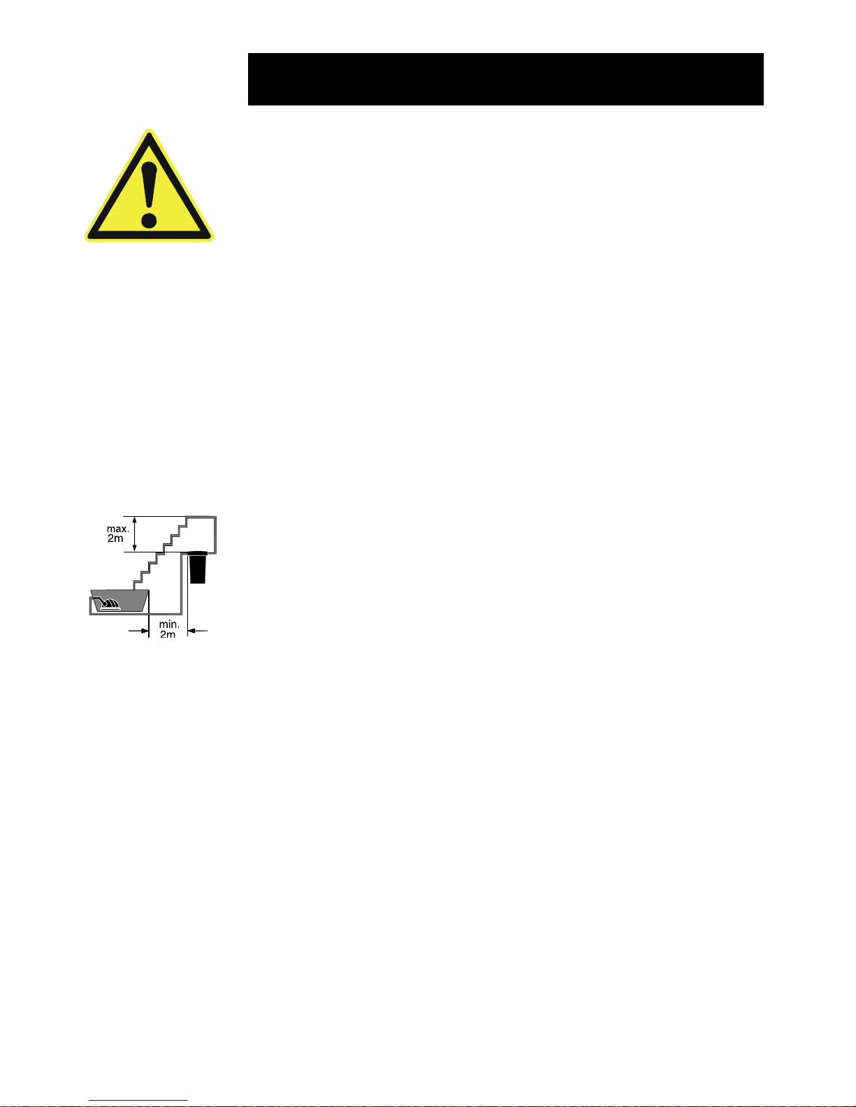
Safety guidelines
Filtoclear pressure filter with integrated UVC
- Caution: Dangerous ultraviolet radiation. The rays from
the UVC lamp are harmful to your eyes and skin! Never
operate the lamp of the Filtoclear UVC outside the casing!
- Set up the Filtoclear with integrated UVC so that it is safe from
flooding. Secure your Filtoclear so that it will not fall into the pond.
It should be placed at least 2m from the edge of the pond.
- Always turn the pump on first before starting up the Filtoclear
UVC. The UVC lamp must not be operated without water
flowing through it.
- Do not use the Filtoclear UVC if the connecting lead, UVC lamp
or casing appear to be defective!
- Do not use the Filtoclear UVC when there are people in the
water!
- Caution: The built-in temperature monitor in the Filtoclear
UVC automatically switches off the UVC lamp if it overheats.
After it has cooled down, the UVC lamp is automatically
switched back on again.
- Never open the casing of the UVC or its accessories unless
expressly directed to do so in the instructions.
- The electrical data of the supply grid must correspond to the
data on the type label.
- Make sure that the Filtoclear UVC is supplied with a measured
fault current not greater than 30mA via a fault current
protection switch (FI or RCD).
- Always disconnect the plugs of the Filtoclear UVC and of all
devices that are in the water before you carry out any work on
the Filtoclear!
- For your own safety, contact an electrician if you have any
questions or problems regarding the electrical connection!
- Never immerse the device in water!
- Only operate the Filtoclear UVC from a safety socket. This
must be installed in accordance with the relevant national
regulations (VDE, EN ...). Make sure that the ground conductor
is securely installed all the way to the Filtoclear UVC.
- Never use installations, adapters, extension or connecting
cables without a safety contact.
- Mains power cables must have a cross-section not less than
that of a rubber hose line with the code HO5 RNF. Extension
cables must comply with the standard DIN VDE 0620.
Instruction for use
P
max
= 0,2 bar
Page 26

26
Instruction for use
- Electrical installations near garden ponds and swimming pools
must comply with international and national installation
guidelines.
- Keep the connecting points dry!
- Do not carry or pull the Filtoclear by its connecting lead!
Protect the connecting lead from heat, oil and sharp edges.
- Lay the hoses and connecting lead in such a way that they are
not an obstacle and do not become damaged!
- Caution! Danger! Never operate the Filtoclear pressure filter
with integrated UVC with a water pressure greater than 0.2 bar
(2mwh)! The height difference between the filter lid and the
pressure-free outlet point can therefore be 2m max. The
maximum delivery pressure of the pump being used must not
exceed 0.5 bar (5mwh).
- Only operate the Filtoclear with pressure hoses that are
approved for at least 0.2 bar, i.e. the maximum pressure of the
pump.
- Check and clean the water outlet to the pond on a regular basis.
The outlet should always be clear, as any blockage would
result in the filter being operated at a pressure greater than 0.2
bar. This in turn would lead to the risk of leaking and therefore
of the pond emptying completely.
- Important: When the Filtoclear is being used in ‘filter’ mode,
the cleaning connection or any drainage hose connected to it
must always be sealed with the sealing cap and inserted flat
seal in order to prevent the pond from emptying. At the same
time the sealing cap acts as a safeguard in case the function
switch is accidentally set to ‘Clean’.
- Make sure that the function switch is always set to ‘Filter’ when
the pump is in operation. The function switch may only be set
to ‘Clean’ when cleaning the filter sponges with the handle
function.
- Before starting up the Filtoclear, check that the connected
hoses, the sealing cap and the tension ring with safety latch are
sitting correctly.
- Never pump any liquids other than water!
- When frost is expected, you must remove the Filtoclear with
integrated UVC.
- Install the Filtoclear where it will not be exposed to direct
sunlight.
- Please observe the local noise protection regulations.
P
max
= 0,2 bar
Page 27

27
How the Filtoclear pressure filter works
The Filtoclear pressure filter with integrated UVC is a sealed filter
system for the biological and mechanical cleaning of pond water.
Instruction for use
A Water inlet
The pump is connected to the water inlet with a pressure hose.
B Pre-clarifying of pond water
As the water flows in, it is briefly exposed to ultraviolet radiation
under the UVC lamp. This kills off germs and bacteria and
inhibits algae growth. The water subsequently flows from the
edge into the filter in a circular fashion.
C Vortex system (settling zone)
Suspended matter and bio-sludge are precipitated by the
centrifugal effect and gravity.
D Mechanical filtering
Dirt particles are trapped by the outer surface of the filter
sponges before the water flows the entire height of the filter from
the edge into the inner chamber of the filter.
GIH
F
A
C
D
E
B
Page 28

28
Installation guidelines with regard to the
clear water guarantee
In order to make any claims on the basis of the clear water
guarantee, the following installation guidelines must be observed.
Definition of clear water:
Clear water is achieved if the fish or stones at the bottom of the
pond can be seen at a depth of 1 m.
Selecting the right system
Please select the filter system using the following table (selection
criteria: pond size and with/without fish population).
Instruction for use
E Biological clarifying
The pores of the filter sponges form a large inner surface which
microorganisms can colonise. The red and blue filter sponges
differ in size and density. This creates zones in which the water
can flow at different speeds. Zones with a high flow speed (blue
filter sponges) favour the colonisation of microorganisms which
convert ammonium to nitrate via nitride (nitrification). Zones
with a low flow speed (red filter sponges) support the colonisation of anaerobic microorganisms which reduce nitrate to
nitrogen (denitrification).
F Water outlet with flow indicator
At the water outlet, the clarified water is fed back into the
garden pond via a pressure hose or a watercourse etc.
G Cleaning connection
When cleaning the filter, a drainage hose can be connected to
the cleaning connection which diverts the dirty water into the
sewerage system or onto a flower bed.
H Function switch
The function switch is used to switch between normal water
discharge into the pond (“Filter“) and the cleaning connection
(“Clean“).
I Cleaning the filter sponges with the handle function
The filter sponges can be cleaned while the Filtoclear is
operational through hard “pumping” by pressing the cleaning
handle.
Page 29

29
Pressure loss due to hoses
Use large hoses if possible in order to minimise pressure loss.
Please use the following hose diameters for hoses up to 4 m in
length:
Filtoclear 3000 1 – 1¼ inches
Filtoclear 6000 1 – 1½ inches
Filtoclear 11,000 1¼ - 1½ inches
For hoses that are longer than 4 m, please always use hoses that
correspond to the upper value of the scale.
In order to avoid pressure loss, cut the spiral stepped hose adapter
at the relevant points for each hose.
Avoid unnecessary corners and bends which contribute to further
pressure loss.
1''
1 ¼''
1 ½''
¾“
The filter system with integrated UVC must be running permanently,
24 hours a day.
The UVC lamp must be replaced after 8,000 hours of operation in
order to ensure that the Filtoclear UVC continues to operate with
optimum effectiveness.
The filter system must be cleaned regularly.
Pressure loss due to height difference
The selection table allows for a maximum height difference of 1 m
between the surface of the water and the highest point of the
filtering system. If the height difference is greater than 1 m, you
should use a correspondingly more powerful pump.
Filtoclear 3.000 Filtoclear 6.000 Filtoclear 11.000
Aquamax 2.000 1.500 l 750 l - - - Aquamax 3.500 2.500 l 1.250 l 3.000 l 1.500 l - Aquamax 5.500 3.000 l 1.500 l 4.000 l 2.000 l 6.000 l 3.000 l
Aquamax 10.000 - - 6.000 l 3.000 l 8.000 l 4.000 l
Aquamax15.000 - - - - 11.000 l 5.500 l
Slight pollution of pond
without fish population
Heavy pollution of pond
with fish population
Instruction for use
Page 30

30
Instruction for use
Installing and connecting the Filtoclear
pressure filter
Installing the Filtoclear pressure filter
Choose a suitable location for the pressure filter. Please note the
installation guidelines regarding the clear water guarantee as well
as the following guidelines:
– Install the Filtoclear pressure filter with integrated UVC so that it
is safe from flooding. Secure your Filtoclear so that it will not fall into
the pond. It should be placed at least 2m from the edge of the pond.
– Place the filter on a firm and level base, e.g. on a slab. The filter
can also be dug in up to the step on the filter box.
– Please ensure that there is unhindered access to the lid in
order to be able to carry out work on the filter, e.g. cleaning the
filter sponges.
– Never operate the Filtoclear pressure filter with integrated
UVC with a water pressure greater than 0.2 bar (2mwh). The
height difference between the lid and pressure-free outlet can
therefore be a maximum of 2m.
Connecting hoses
Decide which hose diameter you need based on the selection
table and the recommended hose according to the installation
guidelines for the clear water guarantee (page 8 and 9). Only
operate the Filtoclear with pressure hoses that are approved for a
pressure of at least 0.2 bar, i.e. the maximum pressure of the
pump. From the OASE range, we recommend the green spiral
hose with the corresponding hose clip.
Note: We recommend warming the hose with hot water, pushing
/ twisting it onto the spiral stepped hose adapter and securing it
with a hose clip. This makes the connection more watertight.
Important!: To avoid pressure loss, cut the spiral stepped hose
adapter at the relevant point to fit each hose (see illustration).
1''
1 ¼''
1 ½''
¾“
Connection at water inlet
Push the union nut onto the black spiral stepped hose adapter.
Push / twist the hose on and secure with a hose clip.
Insert the flat seal into the union nut and screw tight onto the
water inlet nozzle:
P
max
= 0,2 bar
Page 31

31
Instruction for use
Connection at water inlet
Push the union nut onto the black spiral stepped hose adapter.
Push / twist the hose on and secure with a hose clip.
Insert the flat seal into the union nut and screw tight onto the
water inlet nozzle:
Connecting to cleaning connection
You can have a drainage hose permanently connected to the
cleaning connection. This allows you to drain the dirty water
directly into the sewerage system or onto a flower bed.
Important!: When the Filtoclear is being used in ‘filter’ mode, the
cleaning connection or any drainage hose connected to it must
always be sealed with the sealing cap and inserted flat seal in order
to prevent the pond from emptying. At the same time the sealing
cap acts as a safeguard in case the function switch is accidentally
set to ‘Clean’.
To connect the drainage hose, push the union nut onto the
transparent spiral stepped hose adapter. Push / twist the hose
on and secure with a hose clip. Insert the green flow vane into the
union nut and screw tight onto cleaning connection. In order to be
able to seal the open end of the drainage hose with the sealing cap,
you need to push / twist the black spiral stepped hose adapter with
thread onto the hose and secure it with a hose clip. Screw the
sealing cap and inserted flat seal on tight.
Connection to water outlet
Push the union nut onto the transparent spiral stepped hose
adapter. Push / twist the hose on and secure with a hose clip.
Insert the green flow vane into the union nut and screw tight onto
the water outlet nozzle.
Note: We recommend diverting the cleaned water via a small
watercourse, for example, instead of feeding it directly back into
the pond. This enriches the water with additional oxygen.
Page 32

32
Instruction for use
Starting up the pressure filter
Important! Before each start-up, you should check that the
connected hoses, the sealing cap and the tension ring with safety
latch are sitting correctly. The function switch must be set to the
“Filter“ symbol. It is imperative that you read and follow the safety
guidelines before start-up.
1. First switch on the pump
Caution! The UVC lamp must not be operated without water
flowing through it.
2. After starting up the pump, check that all the connections are
watertight. Improve those that are not.
3. Plug the Filtoclear UVC into the mains. The power indicator
lights up with a blue shimmer.
Note: In the case of a new installation, the pressure filter
only reaches its full biological cleaning effectiveness after
a few weeks. Extensive bacterial activity only starts at
temperatures of + 10°C or above.
Cleaning and maintenance of the Filtoclear
The Filtoclear pressure filter is largely maintenance-free. The filter
sponges should, however, be cleaned regularly.
Cleaning the filter sponges with the handle function
Suspended matter and dirt are deposited in the filter sponges over
time. These deposits reduce the effectiveness of the filter, so the
filter sponges should be cleaned regularly, e.g. every two weeks.
Note: The filter sponges should be cleaned when cloudy or
even dirty water flows out of the water outlet and back into
the pond.
You can check how dirty the filter is at the transparent spiral
stepped hose adapter with the green flow vane at the water
outlet.
1. Twist off the sealing cap at the cleaning connection or at the
drainage hose that is connected to the cleaning connection.
Caution: There will be a small flow of water.
2. Pull the function switch up slightly and turn clockwise until it
clicks into the “Clean” position.
3. Pull the cleaning handle hard and “pump” several times. This
squeezes the filter sponges and cleans them mechanically.
4. Press the cleaning handle down until it hits the lid. The two Orings clearly clamp into position.
Page 33

33
Instruction for use
5. The filter will now be rinsed clean. As soon as only clean water
can be seen through the transparent spiral stepped hose adapter
at the cleaning connection, pull the function switch up slightly and
turn anti-clockwise until it clicks into the “Filter” position.
6. Screw the sealing cap with the inserted flat seal tight onto the
cleaning connection or the drainage hose that is connected to
the cleaning connection.
7. The filter is now operational again. Check the water flow into the
pond at the green flow vane.
Washing the filter sponges
If the water flow is too small due to dirty filter sponges and cannot
be improved through cleaning with the handle function, then the
filter sponges must be washed or replaced.
Note: Do not use any chemical cleaning agents so as not to kill
off the microorganisms in the filter sponges.
1. Disconnect the mains plug of the Filtoclear UVC.
2. Switch off the pump and ensure that it cannot be switched on
unintentionally.
3. Remove all hoses by unscrewing the union nuts.
4. Remove the tension ring. To do this, pull back the safety latch,
push in the fastening hook and open the tension ring.
5. Lift off the lid with the filter sponge assembly. Place the lid
upside down on another clean surface. The filter sponges are
lying with the filter plate facing up.
Wear marking:
The filter sponges are pre-stressed. The filter sponges can
fall apart due to the mechanical strain and due to normal
ageing. This can result in a short-circuit in the filter.
To check the filter sponges, they must lie on top of each
other on the lower filter plate without any “air gaps”. The filter
sponges must be replaced if the wear marking on the upper
plate is completely visible (see illustrations)
6. Remove upper filter plate by unscrewing the two screws.
7. Pull off the filter sponges and clean under flowing water. Give
the filter sponges a good squeeze.
Page 34

34
Instruction for use
8. Pull off the lower filter plate.
9. Clean the filter box, the lid with lattice pipe, both filter plates and
the tension ring by spraying them with a water hose.
10.Lift the bypass valve slightly and clean the inlet comb of the
Filtoclear UVC (see illustration).
11.Clean the lid sealing ring and the edge of the filter box.
12.Push one filter plate, with the collar facing up, onto the lattice
pipe and the cleaning rods.
13.The filter sponges are pushed on from the casing lid, starting
with a large blue filter sponge and always alternating with a
small red filter sponge. The cleaning rods lie in the two
openings of the large chamber of the filter sponges.
14.Put the filter plate on with the collar facing down. Fasten the
cleaning rods flush to the filter plate using the two screws.
Important: If the cleaning rods can be pushed through the
holes of the filter plate, the filter plate must be turned 90° onto
the other set of holes. The lattice pipe must be completely
covered by the collar diameter.
15.Place the lid seal onto the upper edge of the filter box (see
illustration).
16.Press the lid with the filter sponge assembly onto the filter box.
17.Place the tension ring onto the edge of the filter box and lid,
press down on the lid and click the fastening into place. Push
the safety latch in. Caution: Do not jam the cable of the
Filtoclear UVC!
18.Fasten all hoses with flat seals or flow vane to the corresponding
connections by screwing the union nuts on tight.
19.Start the pressure filter up again. (see “Starting up the pressure
filter“)
Page 35

35
Replace UVC lamp
The UVC lamp must be replaced after 8,000 hours of operation in
order to ensure that the Filtoclear UVC continues to operate with
optimum effectiveness.
1. Disconnect the mains plug of the Filtoclear UVC.
2. Switch off the pump and make sure that it cannot be switched
on unintentionally.
3. Unscrew the four screws of the Filtoclear UVC and carefully pull
the lamp from the lid of the filter. Note: The screws are screwed
in very deep (approx. 17 mm) in order to allow greater torque to
be applied.
4. Unscrew the clamping screw in an anti-clockwise direction and
remove the quartz tube with O-ring.
5. Pull out the UVC lamp and replace it.
Note: Due to a built-in safety switch the UVC lamp only
works after complete assembly of the Filtoclear. Only
lamps of the type TUV PL-S 9/11W may be used.
6. Clean the quartz tube with a damp cloth.
7. Check the quartz tube and O-ring for damage and replace if
necessary.
8. Screw the clamping screw with quartz tube and O-ring on tight
in a clockwise direction.
Cleaning the quartz tube
1. Disconnect the mains plug of the Filtoclear UVC.
2. Switch off the pump and make sure that it cannot be switched
on unintentionally.
3. Unscrew the four screws of the Filtoclear UVC and carefully
pull the lamp from the lid of the filter. Note: The screws are
screwed in very deep (approx. 17 mm) in order to allow greater
torque to be applied.
4. Clean the quartz tube with a damp cloth.
5. Pull out the flat seal and the protective tube between the lid and
the Filtoclear UVC and clean with water. Check the parts for
damage and replace if necessary. Fit the flat seal under the ring
of the protective tube (see illustration) and insert in lid together.
6. Insert the Filtoclear UVC in the lid of the filter and screw the four
screws on tight by hand (2 Nm).
7. Start the pressure filter up again. (see “Starting up the
pressure filter“)
Instruction for use
Page 36

36
Instruction for use
9. Pull out the flat seal and the protective tube between the lid and
the Filtoclear UVC and clean with water. Check the parts for
damage and replace if necessary. Fit the flat seal under the ring
of the protective tube (see illustration) and insert in lid together.
10.Insert the Filtoclear UVC in the lid of the filter and screw the four
screws on tight by hand (2 Nm).
11.Start the pressure filter up again. (see “Starting up the
pressure filter“).
Storage / winter storage
When frost is expected, you must remove the Filtoclear with
integrated UVC! Clean it thoroughly (see Cleaning and maintenance
of the Filtoclear). Check the Filtoclear with integrated UVC for any
damage. Store the Filtoclear with integrated UVC in a dry and frostfree place. The place of storage must be inaccessible to children.
Advice on disposal
Please dispose of your Filtoclear with integrated UVC in an
environmentally friendly way. Contact your local refuse department
for advice on disposal.
UVC lamps must not be disposed of with domestic waste! Remove
the UVC lamp from the unit and take it to a collection point, so that
it can be disposed of in an environmentally responsible way.
Repair / cable replacement
For repair / cable replacement please send the defective Filtoclear
with integrated UVC directly to the supplier / manufacturer.
Available spare parts are listed under Product overview.
Page 37

37
Instruction for use
Fault
Water not
getting clear
UVC lamp indicator
is not on
No water discharge
from pond inlet
Possible
causes
Unit not been used
for long
Inappropriate pump
capacity
Water is extremely
dirty
Fish and animal
population too large
Filter sponges are
dirty
Quartz tube is dirty
Mains plug of
Filtoclear UVC not
connected
Defective UVC lamp
Faulty connection
Lamp has no UVC
output
Protective tube not
fitted
Filtoclear UVC overheating
Function switch set
to “Clean”
Mains plug of pump
not connected
Pond inlet blocked
Measures
Full biological cleaning effectiveness is only reached after a
few weeks.
Reset pump capacity
Remove algae and leaves from
the pond, change the water
Guideline: approx. 60 cm fish
length to every 1,000 l of pond
water
Clean the filter sponges
Remove the Filtoclear UVC and
clean the quartz tube
Connect the mains plug of the
Filtoclear UVC
Replace the UVC lamp
Check the electrical connection
The lamp should be replaced
after approx. 8,000 hours of
operation
See Replace UVC lamp
After cooling down, UVC
switched on automatically
Reset function switch to “Filter”
Connect the mains plug of the
pump
Clean pond inlet
Troubleshooting
Page 38

38
Technical data
Filtoclear 3000 6000 11000
Dimensions in mm (ØxH) Ø 380 x 310 Ø 380 x 430 Ø 380 x 550
Inlet and outlet ¾“ to 1½“ ¾” to 1½“ ¾“ to 1½“
Filter volume in litres 5 9 1 4
Crystalline filter surface in m² 5. 3 10.5 15.8
Integrated UVC clarifier 9 W 11 W 11W
Nominal voltage UVC 230V/50Hz 230V/50Hz 230V/50Hz
Lamp components UVC TUV PL-S 9W TUV PL-S 11W TUV PL-S 11W
Cable length in m 5 5 5
Weight in kg 5 5.5 6
Instruction for use
Wearing parts
Filtoclear 3000: Spare UVC lamp 9W ID No. 54984
Spare filter set Filtoclear 3000 ID No. 56109
Spare set of seals ID No. 34581
Filtoclear 6000: Spare UVC lamp 11W ID No. 56112
Spare filter set Filtoclear 6000 ID No. 56110
Spare set of seals ID No. 34581
Filtoclear 11000 Spare UVC lamp 11W ID No. 56112
Spare filter set Filtoclear 11000 ID No. 56111
Spare set of seals ID No. 34581
Page 39

39
Instruction for use
Product overview
1 Filter box Filtoclear 3000 ID. 24460
2 Filter box Filtoclear 6000 ID. 24461
3 Filter box Filtoclear 11000 ID. 24462
4 Lid Filtoclear ID. 24459
5 Inner lid Filtoclear ID. 24457
6 Spare UVC lamp 9W ID. 54984
7 Spare UVC lamp 11W ID. 56112
8 Filtoclear UVC 230V/50Hz ID. 24925
9 Quartz tube ID. 22622
1 0 Lattice pipe Filtoclear 3000 ID. 24853
1 1 Lattice pipe Filtoclear 6000 ID. 24854
1 2 Lattice pipe Filtoclear 11000 ID. 24852
1 3 Protective tube Filtoclear UVC ID. 34521
1 4 Spare set of control elements Filtoclear ID. 34579
1 5 Spare set of screw elements Filtoclear ID. 34580
1 6 Spare set of seals Filtoclear ID. 34581
1 7 Spare filter set Filtoclear 3000 ID. 56109
1 8 Spare filter set Filtoclear 6000 ID. 56110
1 9 Spare filter set Filtoclear 11000 ID. 56111
20 Cleaning rods Filtoclear 3000 ID. 24749
21 Cleaning rods Filtoclear 6000 ID. 24748
22 Cleaning rods Filtoclear 11000 ID. 24747
23 Additional pack Filtoclear 3000/6000/11000 ID. 34561
24 Tension ring Filtoclear ID. 34578
Page 40

40
Instruction for use
4
5
6 / 7
8
9
15
15/16
23
16/23
14
14/16
14(2x)/15(12x)
23
16/23
15(12x)
16
15
15
16
15
15/16
15
16
13
16
16
Page 41

41
Instruction for use
1 / 2 / 3
10 / 11 / 12
14/15
14
17/18/19
16
20/21/22
17/18/19
16
24
14/16
15
Page 42

42
Guarantee
A function guarantee of 24 months is given on this OASE
equipment. The guarantee is effective from the original date of
purchase from an OASE dealer. If the equipment is resold, the
guarantee period does not therefore run from the beginning again.
The guarantee certificate is only valid together with the receipt of
purchase. This manufacturer’s guarantee is independent of any
existing guarantee-related claims by the customer against a party
to a contract.
Our guarantee covers faults in material defects or defects in
fabrication. Our guarantee does not apply to claims resulting from
incorrect installation and operation as well as lack of maintenance,
improper use, the effects of frost, furring or inexpert repair attempts.
Wearing parts, such as rotors / light bulbs, are not covered by this
guarantee. A precise definition of the wearing parts is contained in
these instructions, which form part of these guarantee conditions.
Our manufacturing department exclusively uses quality materials.
Should the equipment, in spite of this, give rise to a justified claim,
you will be entitled to have it repaired or the defective parts
replaced free of charge, in accordance with what we deem to be
appropriate.
We reserve the right to charge assembly costs. All guarantee
repairs are carried out by us or by a repair shop authorised by us.
If work is carried out within the framework of the guarantee, in
particular a replacement of parts, this does not mean that the
guarantee period will start from the beginning again.
Should you ever have to make a guarantee claim, please send the
whole unit or component together with your receipt, this guarantee
card and specification of the defect to us, freight prepaid.
We do not accept liability for subsequent damage resulting from
the failure of a piece of equipment.
Complaints due to damage in transit can only be accepted if the
damage was ascertained and confirmed on receipt of the goods
from the forwarding agent, the railway or post office. Only then is
it possible to lodge claims against the forwarding agent, railway or
post office.
Instruction for use
 Loading...