

OARTEC Rowing Simulator Operation Manual
OPERATION MANUAL

CONTENTS
1. ASSEMBLY
Attaching the Seat Rail•
2. OPERATION
Getting Started•
Folding•
Unfolding•
Changing the Resistance•
Adjusting the Feet Height•
Moving the Footstretcher•
Changing the Oar Handles•
Feathering the Oar•
Changing the Oar Pivot Span Positions•
Changing the Oar Height•
Moving•
Storage•
3. WORKOUT MONITOR
Operating Instructions
On/Off•
Setting the Time•
Setting the Distance•
Speed•
Average Data•
Stroke Count•
Technical Data•
Memory•
Heart Rate Monitoring•
Ports•
Batteries•
4. MAINTENANCE
Troubleshooting•
Tensioning the Return Bungy•
Replacing the Drive Straps•
Tools Required•
6. SPECIFICATIONS
Dimensions•
Rigging•
7. CONTACT DETAILS
8. WARRANTY
Thankyou for purchasing the Oartec Rowing Simulator.
Please read this manual carefully to understand the operating procedures, features, functions and maintenance requirements to ensure long term reliability and enjoyment of the Oartec.
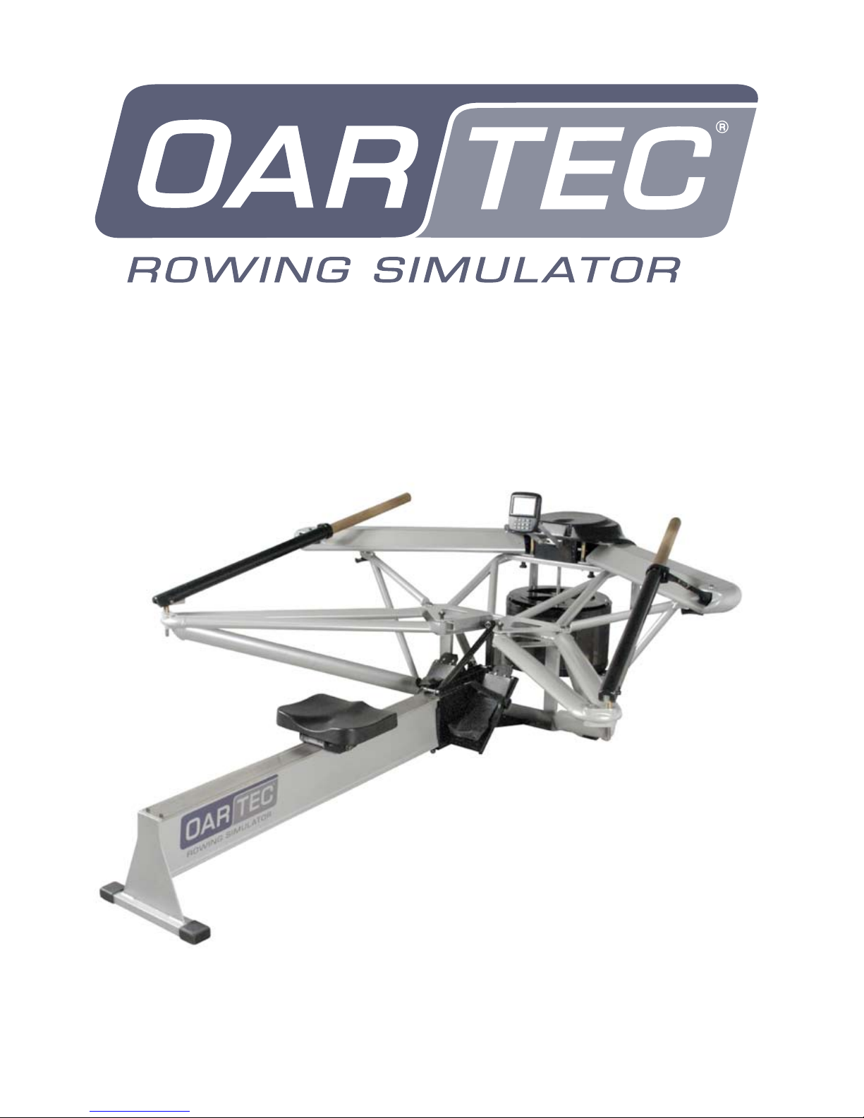
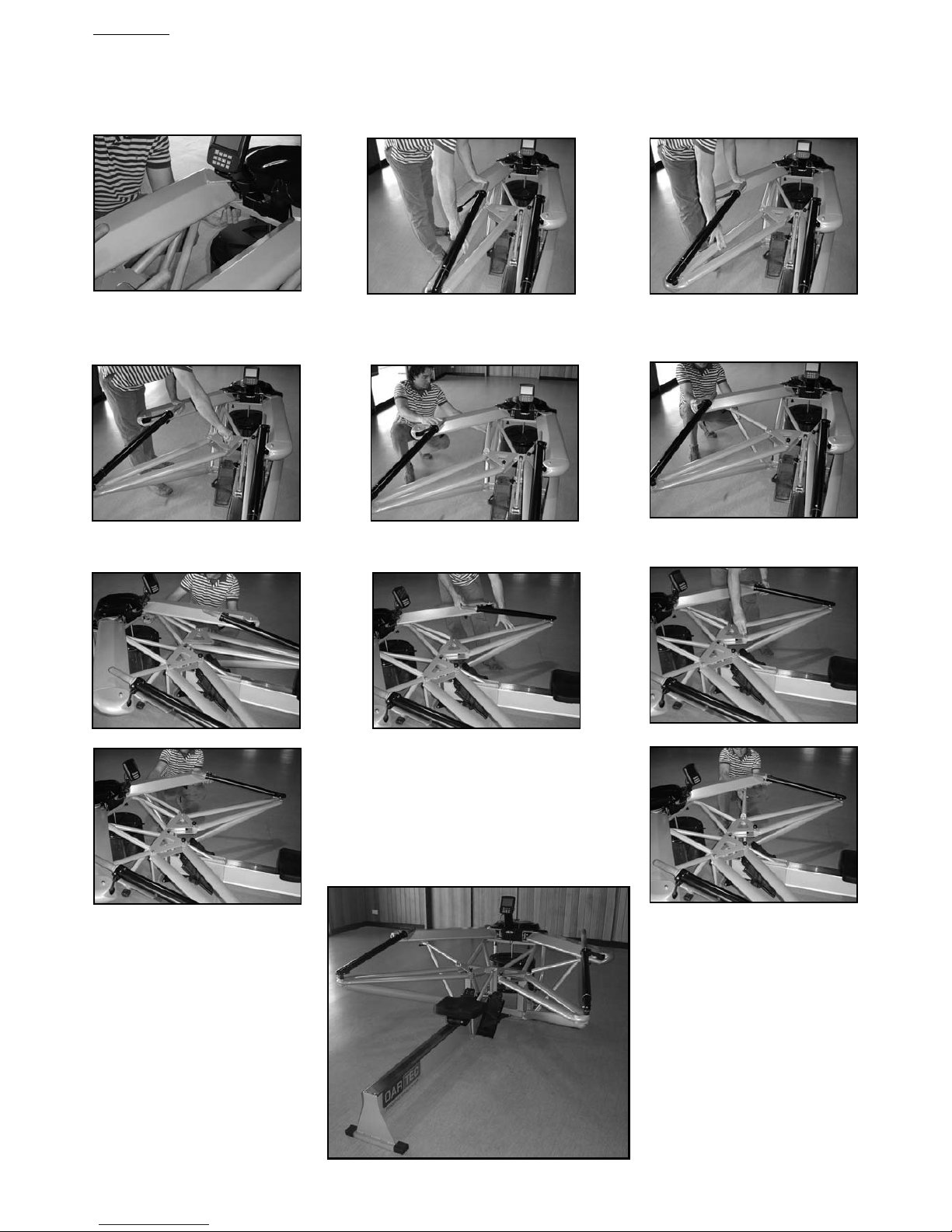
ATTACHING THE SEAT RAIL
Remove the packaging surrounding the Oartec front assembly and unpack the seat rail assembly from
the box. The front assembly can remain upright on the base of the box until the seat rail is attached.
WARNING: When the Oartec is in an upright (vertical) position there is the potential for the machine
to topple over and possibly cause injury. Make sure the Oartec is placed on level ground and is well
positioned away from other objects or persons during the assembly process.
Carefully pick up the rear seat rail section and place vertically onto the frame of the front assembly. It is
recommended to place a piece of cardboard or other padding to protect the coating on the frame from
scratching or being chipped during the assembly.
ASSEMBLY
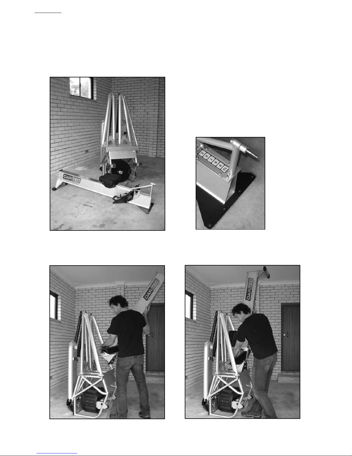
Insert the long bolt through the top
of the seat rail frame. Place the
spacer on the bolt so that it will be
between the seat rail and frame
when connected.
ATTACHING THE SEAT RAIL
Line up the holes on the joining plates and using the bolts provided, insert the bolts into the holes. It is
best to insert the outer bolts first to locate the frame plate and seat rail plate together which will hold the
seat rail stable in this vertical position.
Place the nuts and washers on the outer bolts ready for tightening. Insert the 2 inner bolts through the
remaining holes, thread the nuts and washers on the bolts and then firmly tighten the lock nuts to secure
each of the four bolts.
Insert the long bolt through the seat rail gusset, spacer and frame. When the bolt protrudes through
the other side of the frame, place the washer and nut onto the bolt and tighten using a 17mm hex head
socket ratchet or spanner.
Carefully lower the machine horizontally to the floor and recheck
that the bolts are tight and secure.
Unfold the arms and outriggers (See Unfolding) and the machine
is ready to use.
ASSEMBLY

GETTING STARTED
Once the Oartec seat rail and front assembly are connected, the machine now only needs to be unfolded
(see Unfolding in the Operation section of the manual) and it is then ready to row.
The Oartec is shipped in the sculling configuration but if sweep rowing is the preferred configuration, the
oar handles and pivot position need to be changed accordingly (see Changing the Handles and Changing
the Oar Pivot Span Position in the Operation section of the manual). The sweep handles are shipped in the
large box packaging the front assembly.
Move the footstretcher to the preferred position for either sweep or sculling (see Moving the
Footstretcher). The positions are numbered for quick reference and most users will have a different
footstretcher position for sweep and sculling.
Take a few easy and slow strokes to get used to the feel of the machine. If sculling, the oar heights can
be configured to have Left over Right clearance between the handles, which makes it easier to move the
hands through the crossover during the recovery (see Changing the Oar Height). Choose between having
the oar handles free to rotate in the oar shaft to simulate feathering or keep them in the locked position.
The resistance is changed by moving the lever at the top front of the flywheel housing and the positions
are numbered for quick reference (see Changing the Resistance). Note that the recommended
resistance range for rowing and sculling differ.
The workout monitor takes 4 AA batteries to power the display and needs to be manually turned on by
pressing the On/Off button (for more information and functions see the Workout Monitor section of the
manual).
When the Oartec is assembled in the factory prior to shipping, the bungy tension is set to compensate
for the initial stretch of the bungy. After shipping and initial use of the machine the bungy will stretch and
then settle in but this tension might have to be retuned for optimal performance. This is a simple
procedure and will only need adjustment in small increments (for more information see Adjusting the
Bungy Tension in the Maintenance section of the manual)
OPERATION
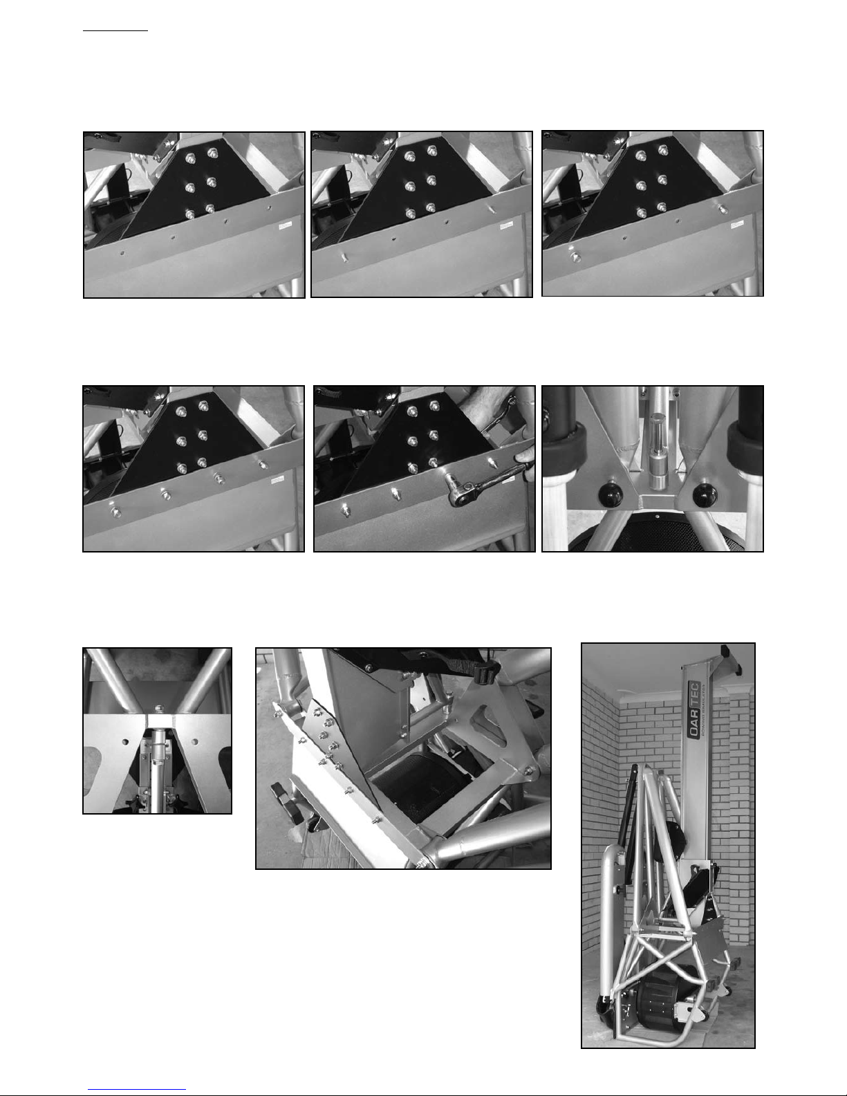
FOLDING
The Oartec Rowing Simulator has been designed to allow the outriggers and drive arms to fold inwards
and reduce the overall width of the simulator when not in use by two thirds for easy relocation, storage
or space saving. This is a simple process and should take less than 1 minute to complete.
To fold down the Oartec follow the procedure set out below.
Loosen the T Knob that connects the drive arm with the brace arm. Pull the brace arm from under the
drive arm and fold inwards toward the flywheel.
Remove the outrigger locking pin and push the drive arm and outrigger inwards simultaneously until the
drive arm locks into position and the outrigger is parallel with the seat rail.
Repeat the process with the opposite side
Place the outrigger locking pin in the frame plate hole
to secure the outriggers when in the folded position.
OPERATION
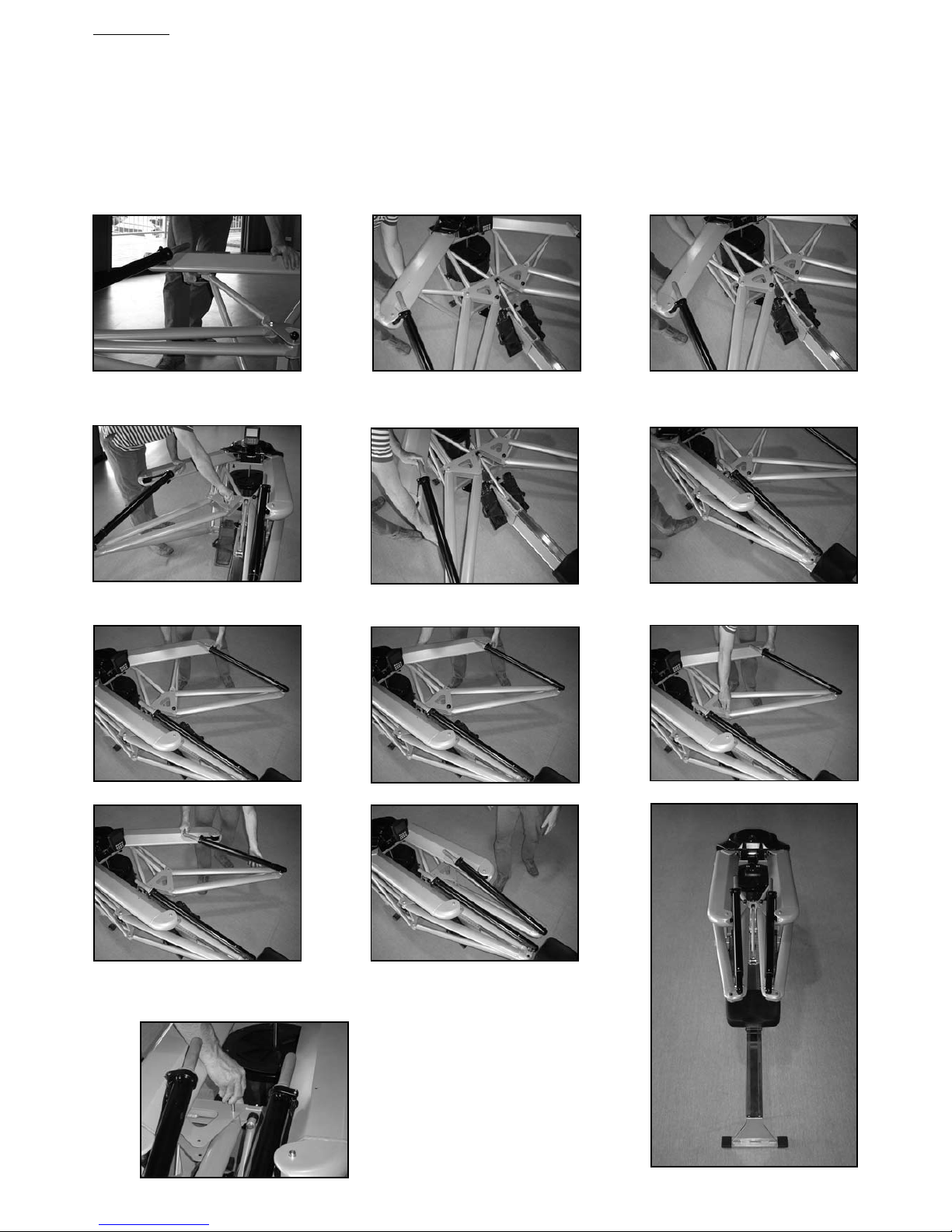
UNFOLDING
Pull the indexing plunger underneath the drive assembly plate to release the drive arm and remove the
outrigger locking pin to free the outrigger. Swing both the arm and outrigger outwards simultaneously.
Insert the outrigger locking pin to lock the outrigger in the operational position. Swing the brace arm into
position and connect with the drive arm.
Repeat the unfolding procedure for the opposite side.
OPERATION

CHANGING THE RESISTANCE
The resistance on the Oartec is provided solely by air resistance and is increased or decreased by
changing the amount of air that enters the flywheel housing system. A shutter mechanism is used to
open or close the air intake area and control the air flow. To adjust the resistance, simply the move the
lever at the front of the shutter mechanism to the left or right.
The total range of resistance is numbered for quick reference and the recommended resistance for
rowing is between positions 10 and 6 and between positions 1 and 5 for sculling. The higher the number
the harder the resistance.
ADJUSTING THE FEET HEIGHT
The feet height on the footstretcher can be easily adjusted higher or lower to a preferred height setting.
To adjust the feet height, pull the top of the plastic Heelflex until it releases from the locking buttons and
slide the Heelflex up or down through the foot bracket into position. Check that both left and right feet
heights are the same by counting the holes above the foot bracket.
The holes are also numbered for quick reference.
OPERATION
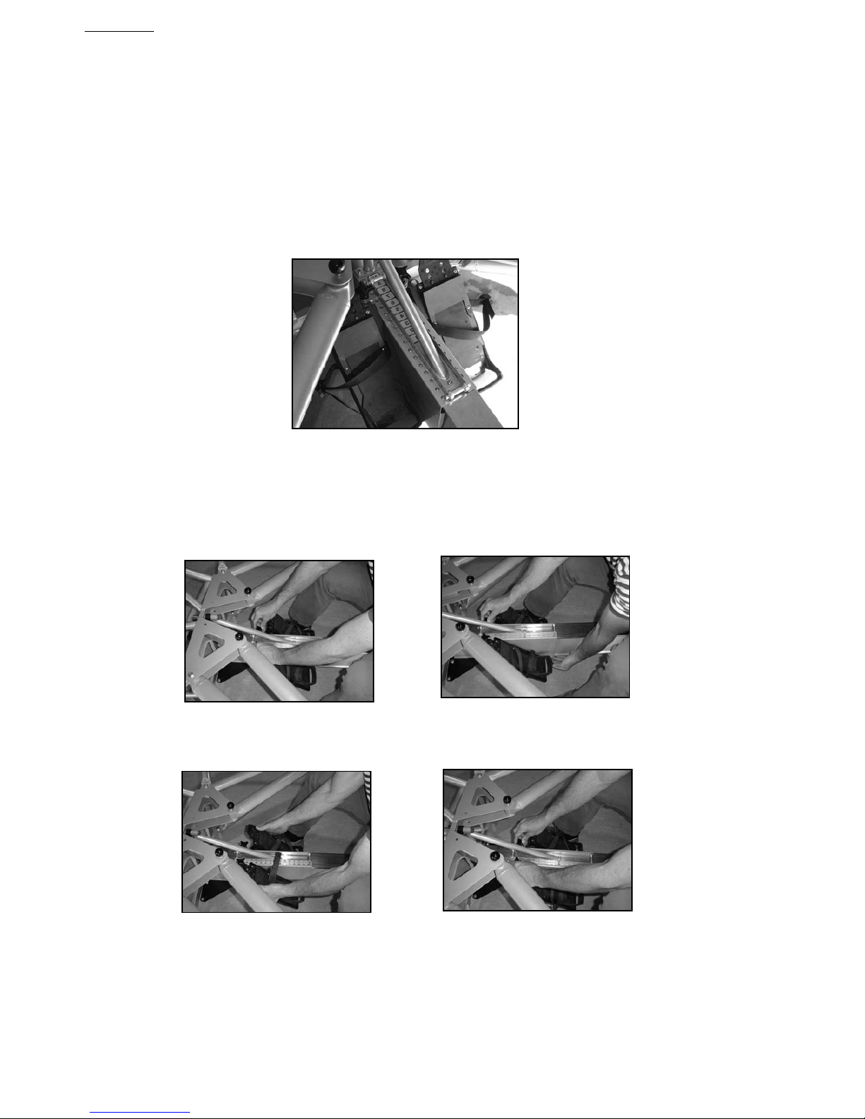
MOVING THE FOOTSTRETCHER
The footstretcher can be moved forward or back along the seat rail to allow for all sizes of rower,
correct position of the handles at the finish or a preferred set up. The positions are numbered for
quick reference.
For sweep rowing it is recommended to begin with the footstretcher in the middle of the adjustment
range (position 5) to be the right distance ‘behind the pin’, and then adjust the footstretcher to the
preferred setting according to height and leg length of the rower.
For sculling the position of the footstretcher will be determined by the leg length of the rower and the
preferred separation of the oar handles at the finish of the stroke. Taller rowers (+6ft) will need the
footstretcher set between positions 6 - 10 and shorter rowers positions 2 - 6 as a rough starting guide.
The footstretcher is secured in place on the seat rail by 2 clamping knobs at top front and 1 clamping
lever underneath at the rear of the centre box. To move the footstretcher, follow the procedure set out
below.
Loosen the clamping knobs located at the top front of the footstretcher center box.
Loosen the locking lever located underneath the seat rail by rotating anticlockwise 3 to 4 turns.
Lift the footstretcher assembly high enough to clear the bolt heads on the seat rail cover plate.
Move the footstretcher assembly forward or back along the rail to the desired position.
Make sure the holes on the footstretcher center box line up with the button heads before securing the
top knobs and bottom lever firmly but not overtight.
OPERATION
 Loading...