

OARTEC DX User Manual
USER MANUAL
DYNAMIC ROWING MACHINE
Introduction
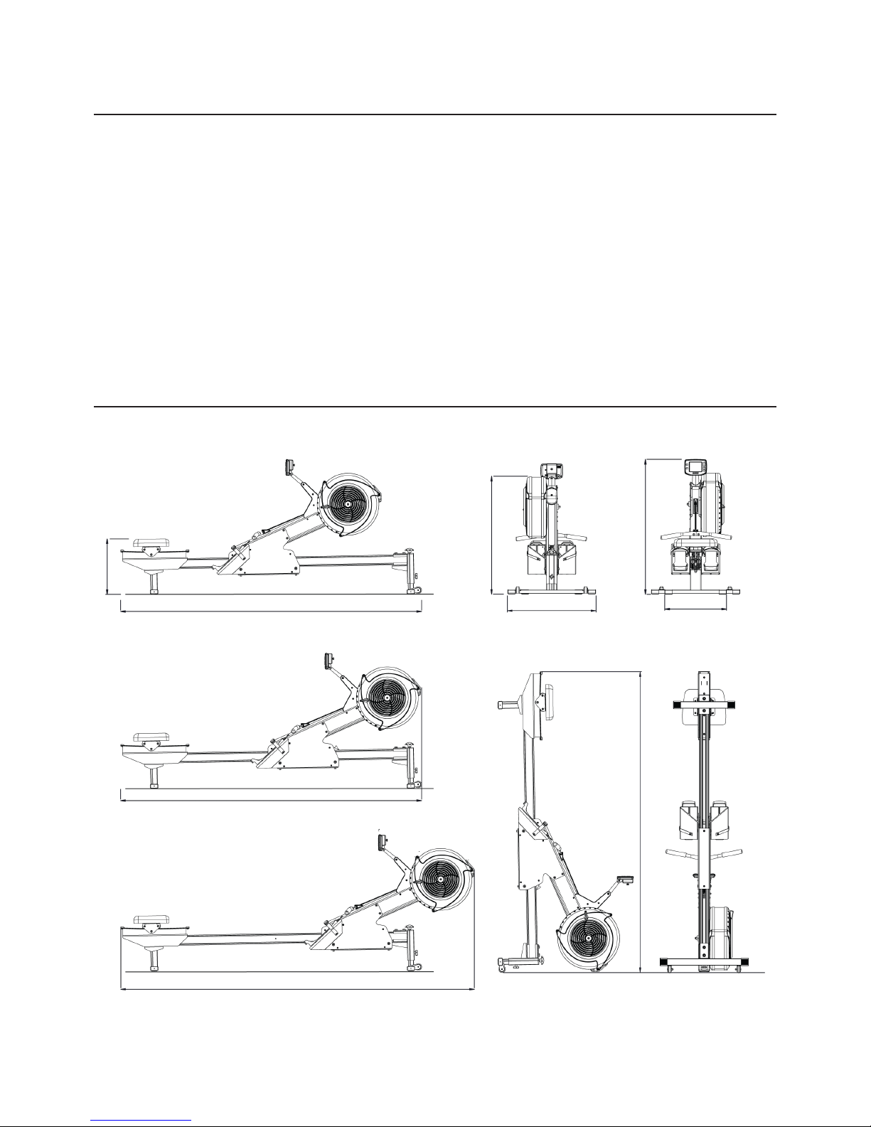
Base length
2.23m/7’4”
Seat height
41cm/16”
Front leg width
66cm/26”
Flywheel height
90cm/35”
Thankyou for purchasing the Oartec DX.
Indoor rowing is one of the best overall fitness exercises for the body.
Dynamic indoor rowing makes it even better because you are achieving the
same workout but without the wear and tear on the body, lower back and joints.
We are proud to be helping you achieve your fitness goals.
Please read the DX user manual carefully, following the procedures to assemble,
set up and maintain you DX in optimal working condition.
Enjoy your rowing!
Rear leg width
45cm/18”
Overall height
101cm/40”
Length locked
2.23m/7’4”
Maximum overall length
2.62m/8’7”
Length upright
2.23m/7’4”
Dimensions

Table of Contents
1. Assembly 3
Unpacking the box 3
Box contents 3
Step 1: Attaching rear leg, seat base to rail assembly 4
Step 2: Building front leg assembly 5
Step 3: Front assembly to rail assembly 6
Step 4: Front leg to rail assembly 7
Step 5: Seat to seat base 7
2. Getting Started 8
Adjusting the bottom roller wheels 8
Setting the front leg height 9
Locking the rolling frame 10
Storing the DX upright 10
Adjusting the feet height 11
Adjusting the footstraps 12
Storing the handle 12
Adjusting the resistance 13
Ready to row 13
3. Oartec Training Monitor OTM-2 14
Installing the batteries 14
Setting the date and time 14
Quick start guide 15
Setting workouts 16
Memory/Rerow 16
4. Maintenance 17
Cleaning the rails 17
Cleaning the seat track and wheels 17
Oiling the chain 17
Adjusting the bottom roller wheels 18/19
Cleaning the flywheel and flywheel housing 20
5. Troubleshooting 21
6. Warranty 22
2
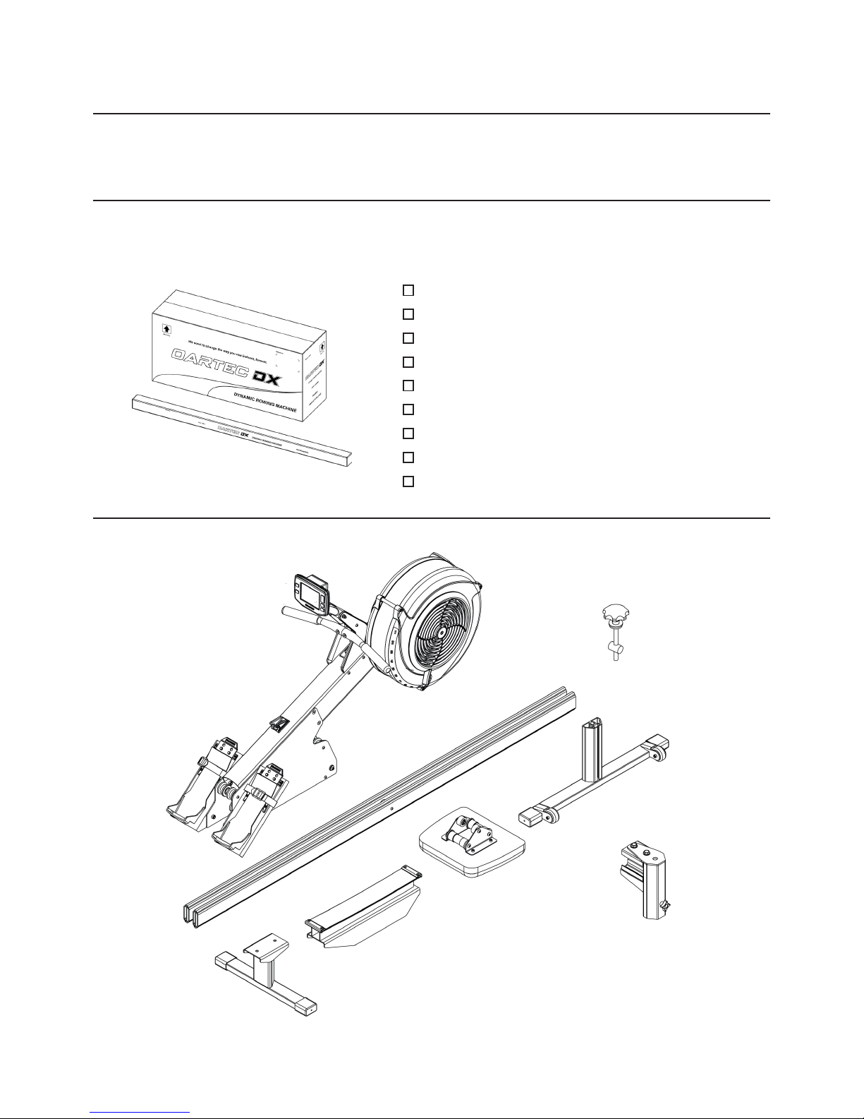
Box Contents
Unpacking the Box
1. ASSEMBLY
Please follow the assembly procedures below.
Assembly should take approximately 20 minutes and if possible get the help of a second person for the lifting.
Carefully unpack the box contents and lay out on the floor. With the help of a second person remove the front
assembly first. If assembling on a hard surface, use a drop sheet or blanket to protect the parts from damage
during assemblly. Check the contents of the box against the checklist below.
Front assembly
Seat assembly
Rail assembly
Front leg inner
Front leg outer
Rear leg
Seat base
Height adjuster assembly
Too l s
3
Front assembly
Rail assembly
Rear Leg
Seat Base
Seat assembly
Front leg inner
Front leg outer
Height adjuster
assembly
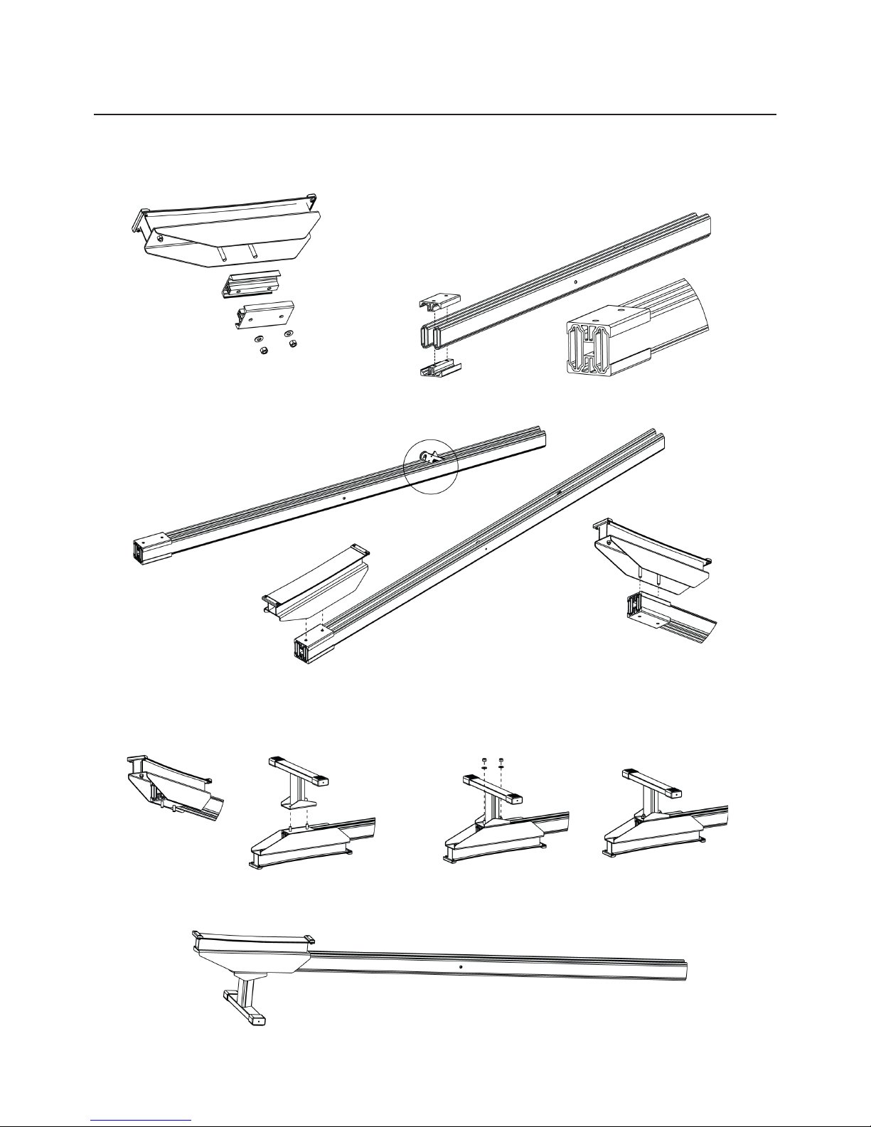
Step 1: Rear Leg and Seat Base to Rails
Tools required: 17mm wrench
4
1. Remove the rear extrusion mounts from the seat
base bolts.
5. Carefully roll the assembly over and rest on floor.
Attach the rear leg to the seat base bolts.
7. Turn assembly over and rest on floor.
4. Insert the seat base bolts
through the top extrusion mount.
IMPORTANT
3. Check that the locking latch opens on the top
rail edge. If it opens to the bottom, simply roll the rail
assembly over to orientate correctly.
2. Attach the extrusion mounts to the top and bottom
of the rear of the rail assembly, with the latch at the
front.
6. Add washers and nuts and firmly tighten with
17mm wrench but do not ovetighten.
Rear
Top
Front
Bottom

Tools required: 17mm wrench
Step 2: Assemble Front Leg
5
1. Remove all parts from height adjuster threaded
axle assembly.
2. Insert the 20mm pin into the inner front leg hole
with the thread aligned vertically.
3. Screw the threaded flange into and
through the threaded pin by about 25mm/1”.
Add M16 washer.
4. Loosen the clamping knob.
Align the clamping plate square in the
slot as the outer front leg slides over
the inner leg.
5. Slide the outer leg down until
the axle protrudes through the top
plate.
6. Thread the M10 half nut and
knob onto the top of the height
adjuster thread.
7. While holding the knob, tighten
the nut with the 17mm wrench up
against the knob to secure in position.

Step 3: Front Assembly to Base Rails
No tools required
6
2. Carefully lift the front assembly and align the rail
ends with the gap between the top and bottom rollers.
** If available, get the help of a second person.
Slide the front assembly onto the rails until the rails
protrude through the other side.
3. While continuing to support the weight
of the front assembly, slide the front assembly
down the rails until it meets the box.
4. Lift the front assembly and rails over the box so
the front assembly can continue to slide down the
rails and rest touching the seat base. Once clear of the
box underneath, place the front of the rails back down
onto the seat box.
5. Check again that the rails and front assembly are
balanced and stable before leaving.
1. Place the empty seat box on the floor. Rest the
rail on the top of the seat box about along the rail
length toward the front. Check that it is stable before
leaving.
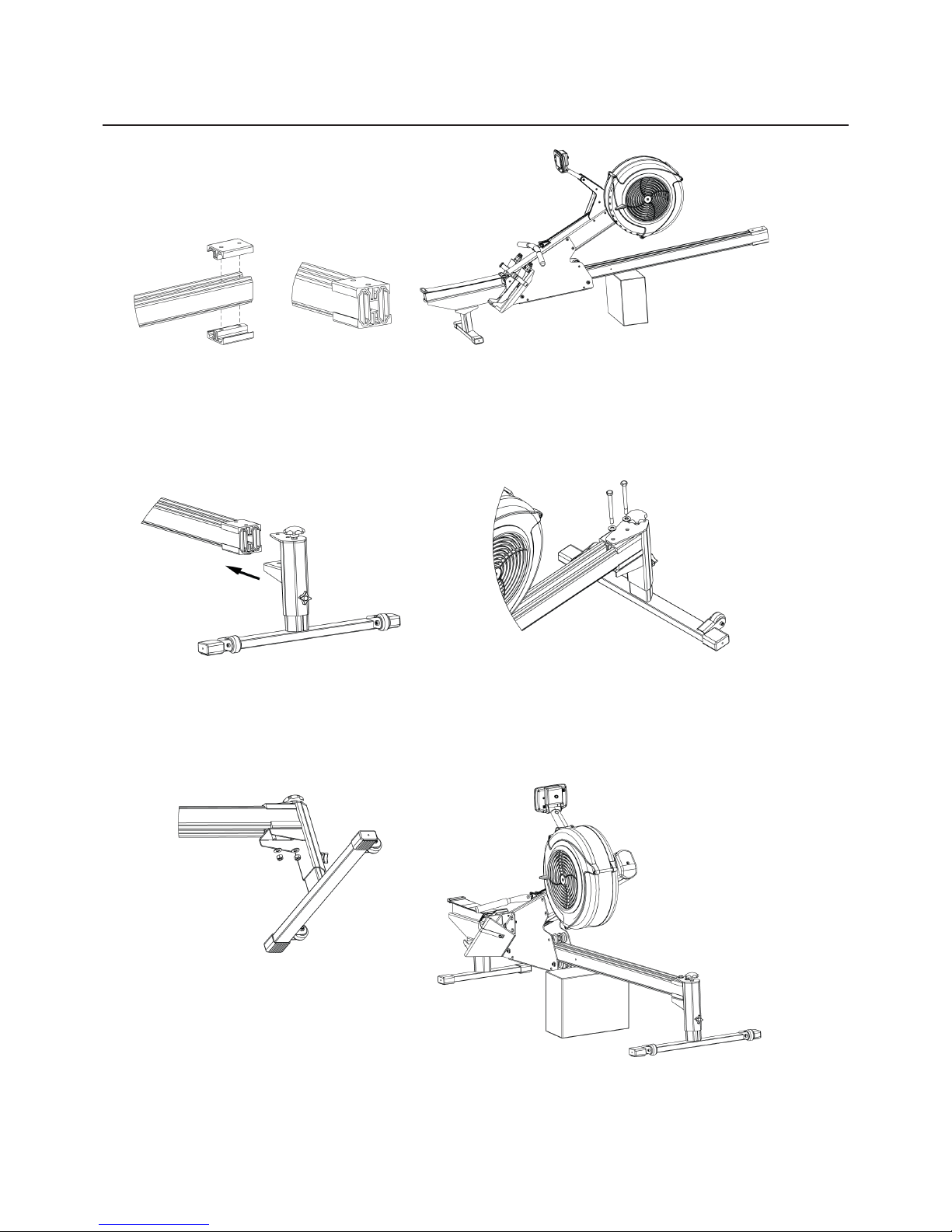
Step 4: Front Leg to Base Rails
7
Tools required: 16mm and 17mm wrench
1. Align the front extrusion mounts to the top and
bottom of the rails. Push the mounts tight onto the rails
and level with the end of rails.
2. Slide the front leg bracket over the
extrusion mounts and align bracket holes with
the extrusion mount holes.
3. Place washers over the bracket holes and insert
bolts through washers and the top and bottom
extrusion mounts. Gently tap or shake the front leg to
help the bolts through the holes.
4. Add washers and nuts to the underside
bolts and tighten with the 16mm and 17mm
spanners.
5. Remove the seat box from underneath the
rails and place front leg on floor.
 Loading...