

INSTRUCTION MANUAL
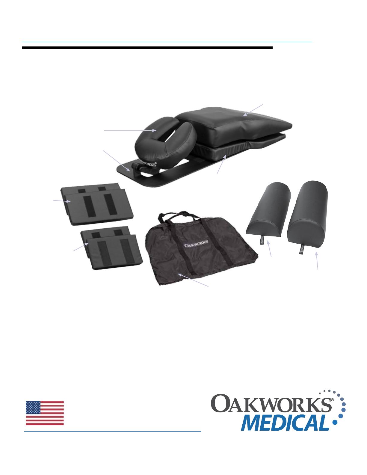
SPINE POSITIONING SYSTEM
(1) CresCent
FaCe rest Pad
(1) radioluCent
Frame With
adjustable
FaCe rest
(2) Contoured
torso Wedges
pictured here with
(2) 8” x 16”
reCtangular
adjuster Pads
small wedge
(1) Contoured
torso suPPort Pad
(2) 7” x 12”
reCtangular
adjuster Pads
made in the USA
with US & imported parts
(1) Carry Case
(1) 8” halF
round
bolster
(1) 8” semi
round
bolster

© Copyright 2010
Oakworks® Medical Equipment,
a division of Oakworks®, Inc.
REGULATORY
FDA Listed
Printed in U.S.A.
All rights are reserved. No part of this
document may be photocopied, reproduced
or translated to another language without
prior written consent of O
Medical Equipment, a division of
Oakworks®, Inc.
Oakworks® is a registered trademark
of Oakworks®, Inc.
akworks
®
Notice
The information contained in this document
is subject to change without notice and
should not be construed as a commitment
by Oakworks®, Inc.
Oakworks®, Inc. assumes no responsibility
for any errors that may appear in this
document nor does it make expressed
or implied warranty of any kind with
regard to this material, including, but not
limited to, the implied warranties of
merchantability and fitness for a particular
purpose.
Oakworks®, Inc. shall not be liable for
incidental or consequential damages in
connection with or arising out of the
furnishing, performance, or use of this
document and the program material
which it describes.

TABLE OF CONTENTS
IntroductIon ......................................................................... 2
WarnIngs & cautIons .................................................2 - 3
symbol IdentIfIcatIon ........................................................ 4
descrIptIon of components ...................................5 - 7
dIrectIons for use ......................................................8 - 15
maIntenance & servIce........................................17 - 21
• cleaning & disinfecting ...................................17
• maintenance .................................................... 18-19
• list of parts ...........................................................20
• specifications ........................................................ 21
• warranty ................................................................ 21
• contact information ................. back cover
TABLE OF CONTENTS
1

INTRODUCTION / INDICATIONS / WARNINGS
INTRODUCTION
The Spine Positioning System is an integral component of the pain management
uoroscopy suite. With this system procedural set up time is reduced, patient comfort
is enhanced and unwanted movement is minimized. Most importantly, the target anatomy is more readily visualized which allows the physician to perform spine procedures
in a more efcient and secure manner. In collaboration with leading pain management
physicians, Oakworks designed the Spine Positioning System in an effort to achieve the
critical balance between optimal imaging and patient comfort. The radiolucent adjustable
frame and versatile padding system provide a metal free imaging support platform capable
of quickly positioning a wide variety of patient physiques for extended periods of time.
The adjustable face rest position provides individualized positioning for all types of cervical
procedures and anatomy. The contoured torso support pad is complimented by a host of
uniquely shaped and sized adjuster pads and wedges that enable a multitude of positioning
combinations for ideal patient comfort and imaging needs for all spinal column procedures.
INDICATIONS
The Oakw ork s® Spine Positioning System is a patient cradle device for use in
diagnostic and therapeutic procedures of the spine. It is intended to be used solely for
the purpose of aiding in patient positioning and comfort during non-surgical
imaging or spinal injection procedures. It may also be used during minimally
invasive surgical procedures such as vertebroplasty or kyphoplasty. The Spine
Positioning System, its secondary components and optional components are
suitable for use in fluoroscopy suites.T
WARNING
WARNINGS
A patient safety strap is required during all procedures. Follow normal and required
safety protocol for all procedures where the patient is in an elevated position for the
procedure (straps, attendants, etc.). Always be certain that attending staff is aware of
the patient’s position while the device is in use. Reposition the patient if necessary
to promote stability. Due to the increased distance between the patient and the table
surface, additional safety measues are recommended when the table top is not used
in a level position due to the risk of the patient falling off the table.
The Oakw ork s® Spine Positioning System is not designed for use with diagnostic x-ray systems where the x-ray generator is located above the radiographic table
and the film cassette or image intensifier is located below the radiographic table.
The X-Ray generator MUST BE located below the radiographic table. The Spine
Positioning System is not designed for use with magnetic resonance imaging systems. The Spine Positioning System is not intended for use in cranial procedures.
Do not overhang the platform frame beyond the warning line on the frame.
Operate the C-arm of the fluoroscopy system with the Spine Positioning System
in place before using the device with a patient for the first time. Make sure there is
adequate clearance to permit free C-arm rotation for both the patient and the positioning device.
Do not permit the patient to push down on the Crescent Face Cushion in an effort
to lift themselves up while dismounting the platform and/or the
fluoroscopy table.
The Spine Positioning System should generally not be used when a patient is under general
anesthesia, especially when prolonged cases are performed. This will reduce
the risk of ocular or facial nerve injury.
2

CAUTION
CAUTIONS
The cushioning foam contained within the Torso Support will lose its ability to
spring back to the original position over time and the amount of foam compression will
increase. Therefore, the Torso Support should be replaced periodically to ensure the
device functions as intended.
To prevent the potential of cross-contamination, it is strongly advised to use barrier techniques when the device is in use. A disposable or laundered patient gown, or disposable pad
are satisfactory for use as a barrier for the Torso Support and other components and accessories, except when the patient presents with pathology that would indicate otherwise. A
disposable face rest cover should be used to cover the Face Rest Cushion. Contact Oakworks
for ordering information. Barrier techniques should be used in addition to disinfection procedures,
not in lieu of them.
Be sure to support the weight of the patient’s head while making adjustments to the cervical
positioning feature of the Platform Frame. Make sure all cam locks are secure before
relinquishing support of the positioning assembly.
The Cervical Support System (see page 5) has metal parts that can cause back scatter of x-rays.
When x-rays are present, wear a suitable radiation barrier.
The Spine Positioning System is constructed using metal pins in the Quick Cam Locks and
aluminum tubing in the support structure. These are out of the field of view in most A-P and
oblique tilted views. Place the positioning assembly according to the recommendations in the
directions for use to eliminate, or reduce any artifacts. If artifacts still remain to the extent that
they would compromise the efficacy of needle placement, discontinue use of the device during the affected procedure.
CAUTIONS
All materials used in the construction of the device and accessories are safe for
temporary and moderately frequent human contact. The device is not intended
for prolonged contact.
Do not use the Face Rest Support Arms as a handle to carry the Spine Positioning System.
Follow maintenance instructions found near the end of this manual. Mechanical components
should be checked periodically to insure that they are functioning properly to insure the safety
of the patient.
3
SYMBOL IDENTIFICATION
SYMBOL IDENTIFICATION
This symbol, when used in this manual and on product labels, represents a caution
warning. Be sure to read and comply with all precautions and warnings.
This symbol, when used in this manual and on product labels, indicates the
potential of exposure to harmful x-rays. Be sure to read and comply with all
warnings.
This symbol, when used in this manual and on product labels, indicates that the
table and components are a Type B Applied Part pursuant to IEC 601.1 and EN
60601-1: 1990.
This symbol when used in this manual or on product labels, warns that when
stacking containers during transport and storage, there should be do not stack
more than 5 containers high.
This symbol, when used in this manual or on product labels, indicates that the
product should be protected from moisture. The humidity specifications for
Transport & Storage are listed on page 23.
This symbol, when used in this manual or on product labels, indicates that
information is given regarding the recommended temperature limits during
transport and storing.
This symbol, when used in this manual or on product labels, indicates
the date of manufacture of the device.
4
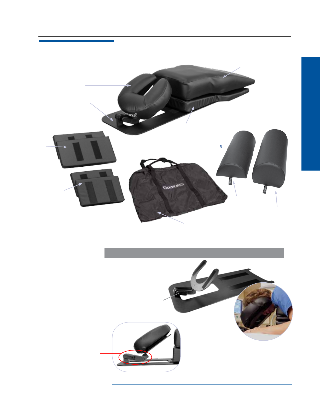
DESCRIPTION OF COMPONENTS
(2) 8” x 16”
reCtangular
adjuster Pads
Pn 0552-06
(2) 7” x 12”
reCtangular
adjuster Pads
Pn 4402-06
(1) CresCent
FaCe rest Pad
Pn em2410-sP
(1) radioluCent
Frame With
adjustable
FaCe rest
Pn 64878
(2) Contoured
torso Wedges
Pn 0550-06 (small)
Pn 0554-06 (large)
large not shown
(1) Carry Case
Pn 64705
(1) Contoured
torso suPPort Pad
Pn 0546-06
(1) 8” halF
round
bolster
Pn 1581-06
DESCRIPTION OF COMPONENTS
(1) 8” semi
round
bolster
Pn 5932-06
64878- RADIOLUCENT FRAME
Used to support the Torso
support and Crescent face
rest pad. One cam lock
facilitates cervical flexion
and extension.
Cervical
Support
System
See Caution on page 3.
cam lock
Adequate free
space under see
through face section
for aeration, supplemental O2, jaw/face
contact as necessary; prevents
patient overheating, can more
easily communicate with the
patient without sound mufing.
5
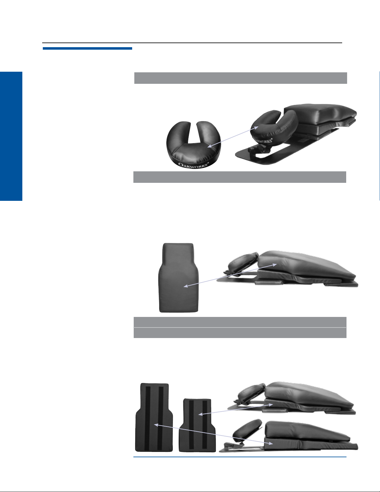
DESCRIPTION OF COMPONENTS - CONTINUED
EM2410-SP - CRESCENT FACE REST PAD
The Crescent Face Rest Pad supports the patient’s face in a prone position without compromising air space for breathing. The face pad can be moved caudad
in situations to prevent imaging of the locking mechanism
when performing upper cervical procedures
that require substantial imaging angulation.
0546-06 CONTOURED TORSO SUPPORT PAD
DESCRIPTION OF COMPONENTS
The Contoured Torso Support is constructed of dense foam in the center,
flanked by softer foam and covered in a fabric designed to withstand today’s
disinfectants. The softer foam accommodates to the patient’s shoulders and/or
breasts to maximize comfort. This helps provide enhanced patient stability while
allowing for the shoulders to decend for optimal cervical and thoracic imaging.
The distal end of the torso support pad is hollowed out under the abdomen to
enhance patient comfort and stability. Additionally, the distal end of the torso
support pad is wider to enhance patient stability by reducing sway while in the device.
0550-06 SMALL CONTOURED TORSO WEDGE
0554-06 LARGE CONTOURED TORSO WEDGE
The Contoured Torso Wedge is constructed of dense foam and covered in a fabric
designed to withstand today’s disinfectants. This provides enhanced patient stability
and conveniently reduces shoulder interference during cervical procedures. For faster
set up, the larger torso wedge can replace the combination of the smaller wedge and
rectangular adjuster pads as shown here.
Large wedge
Small wedge
6

DESCRIPTION OF COMPONENTS - CONTINUED
4402-06 7” X 12” RECTANGULAR ADJUSTER PAD
The 7” x 12” Rectangular Adjuster pads are used either individually or combined to
reduce lumbar lordosis and/or increase chest height to allow for shoulders to naturally decend out of the plane of the cervical and thoracic spine. These pads offer a wide
range of flexibility for general patient positioning and stabilization.
0552-06 8” X 16” RECTANGULAR ADJUSTER PAD
The wider 8” x 16” Rectangular Adjuster pad can be used either individually or
combined to allow those with a shorter humerus to allow the forearm and elbow
to rest and stabilize on a flat surface. Additionally, these can be used as the 7” x
12 adjuster pads are utilized, with a wider support.
DESCRIPTION OF COMPONENTS
1581-06 8” X 26” HALF ROUND BOLSTER
5932-06 8” X 26” SEMI-ROUND BOLSTER
These bolsters may be placed under the patient’s ankles to enhance positioning stability. Two different bolster sizes are provided to allow for patient comfort.
8” halF
round
bolster
8” semi
round
bolster
7

DIRECTIONS FOR USE
DIRECTIONS FOR USE
PREPARATION FOR USE
Unpack and inspect all components. Identify the components and their use with the pictures located in the
Description Section of these instructions.
All components are shipped in a clean but not sterile condition. If the Spinal Imaging Platform will be used for
an indicated surgical procedure, be sure to disinfect the components prior to use. Disinfectants that can be used
are described in the Cleaning & Disinfecting Section of these instructions.
CAUTION - Do not overhang the platform frame beyond the warning line on the frame.
WARNING - A patient saftey strap is recommended during all procedures. A patient saftey strap must be used
during procedures where lateral roll function is used.
FACE REST PLATFORM ADJUSTMENT
Step 1 - open cam Step 2 - Grasp platform and raise to
desired position
Step 4 - Continue to close cam. Step 4 - Force will increase as cam
is near nal position. Close cam to
the nal position
Step 3 - Begin to close cam making
sure that the small locking pins enter
corresponding positioning holes
(Minor platform “rocking” may be
necessary for the pins to enter the
holes). The cam should move freely
at this point (Do not force the cam)
Step 5 - Double check platform by
applying downward force (platform
will easily support over 80 lbs.).
Your face rest platform is now
securely locked.
8

DIRECTIONS FOR USE
SAFE TRANSPORT OF YOUR SPINE POSITIONING SYSTEM
Use the supplied carry case.
Open the cam lock on the adjustable face rest and rotate
the facerest flat against the base frame. This will protect the
facerest support platform during transport.
DIRECTIONS FOR USE
When placing the Spine Positioning System in the bag, put some
pads, wedges or bolsters on both sides of the base frame.
Spine Positioning System Pads
Spine Positioning System Pads
Spine Positioning System
Radiolucent Frame
9

DIRECTIONS FOR USE
FACTITIOUS PATIENTS
The following eight scenarios in factitious patients will demonstrate:
1. Various body types using the Spine Positioning System
2. Their positioning and specific configurations of the SPS used in particular clinical situations
3. Various fluoroscopic images of these factitious patients that exemplify the value of the SPS
DIRECTIONS FOR USE
WARNING
See warnings on page 2.
patIent - alIcIa
Alicia
A patient safety strap must be used for all procedures.
components used: Platform Frame (1), Crescent Face Cushion (1),
Contoured Torso Support Pad (1), Small Contoured Torso Wedge (1),
7” x 12” Rectangular Adjuster Pad (1), 8” Semi-Round Bolster (1)
Alicia in the SPS while obtaining
a C3 pillar view.
Demonstrates the generous amount
of space under the head/face while
laying comfortably in the SPS.
Lateral view of
the cervical spine.
The C2-3 to C7T1 interspaces are
easily visualized
for all posterior
approach cervical
procedures.
10
Right C3 and C4
pillar view of
Alicia. The target
articular pillars
are visualized
for posterior
approach facet/
medial branch
procedures.

DIRECTIONS FOR USE
WARNING
A patient safety strap must be used for all procedures.
See warnings on page 2.
patIent - don
components used: Platform Frame (1), Crescent Face Cushion (1), Contoured Torso Support Pad (1),
Small Contoured Torso Wedge (1), 8” x 16” Rectangular Adjuster Pad (2), 8” Half Round Bolster (1)
Don
Don in the SPS while obtaining an
oblique image of the lumbar spine.
SPS congured with two extra adjuster pads under the
lumbar spine as a method to reduce lumbar lordosis
and enhance comfort.
DIRECTIONS FOR USE
Lateral image of the
lumbar spine.
Right oblique image of the
lumbar spine.
AP image of the lumbar spine.
11

DIRECTIONS FOR USE
WARNING
See warnings on page 2.
patIent - lIz
components used: Platform Frame (1), Crescent Face Cushion (1), Contoured Torso Support Pad (1),
Small Contoured Torso Wedge (1), 7” x 12” Rectangular Adjuster Pad (1), 8” x 16” Rectangular Adjuster Pad (1),
8” Semi-Round Bolster (1)
DIRECTIONS FOR USE
A patient safety strap must be used for all procedures.
Liz
Liz in the SPS while obtaining an AP
image of the upper thoracic spine.
Liz in the SPS while obtaining a
lateral image of the upper thoracic
spine.
Conguration of the SPS for positioning Liz.
AP image visualizing the T1-2
interlaminar space.
optIonal set up:
Platform Frame (1), Crescent Face Cushion (1)
Contoured Torso Support Pad (1), Large
Contoured Torso Wedge (1), 8” Semi-Round
Bolster (1)
Lateral image primarily through the
C7—T2 segments.
Contralateral oblique showing the
upper thoracic facet joints.
12

DIRECTIONS FOR USE
WARNING
A patient safety strap must be used for all procedures.
See warnings on page 2.
patIent - mary
components used: Platform Frame (1), Crescent Face Cushion (1), Contoured Torso Support Pad (1),
Small Contoured Torso Wedge (1), 7” x 12” Rectangular Adjuster Pad (1), 8” Half Round Bolster (1)
Mary
Mary in the SPS while
obtaining an AP image
through the C1-2 segment.
AP image through the
C1-2 joints.
Lateral image through the
C1-3 segments.
DIRECTIONS FOR USE
patIent - suzIe
components used: Platform Frame (1), Crescent Face Cushion (1), Contoured Torso Support Pad (1),
Small Contoured Torso Wedge (1), 8” Half Round Bolster (1)
Suzie
Suzie in the SPS while
obtaining a lateral image
through the C7-T1 segment.
AP image visualizing the
C6-7 and C7-T1
interlaminar spaces.
Lateral image visualizing
the C6-7 and C7-T1
interspaces.
13

DIRECTIONS FOR USE
DIRECTIONS FOR USE
WARNING
A patient safety strap must be used for all procedures.
See warnings on page 2.
patIent - carl
components used: Platform Frame (1), Crescent Face Cushion (1), Contoured Torso Support Pad (1), Small Contoured
Torso Wedge (1), 7” x 12” Rectangular Adjuster Pad (1), 8” x 16” Rectangular Adjuster Pad (2), 8” Semi-Round Bolster (1)
Carl
AP image of the mid-thoracic spine.
Conguration of the SPS for positioning Carl.Carl in the SPS while obtaining an
AP image of the mid-thoracic spine
for planning the trajectory for a left
thoracic facet injection.
Contralateral oblique showing the
trajectory for targeting the midthoracic facet joint.
14
Right thoracic oblique image to visualize the
trajectory for a transforaminal injection.

DIRECTIONS FOR USE
WARNING
See warnings on page 2.
patIent - debbIe
components used: Platform Frame (1), Crescent Face Cushion (1), Contoured Torso Support Pad (1),
Small Contoured Torso Wedge (1), 7” x 12” Rectangular Adjuster Pad (1), 8” x 16” Rectangular Adjuster
Pad (1), 8” Semi-Round Bolster (1)
A patient safety strap must be used for all procedures.
Debbie
Debbie in the SPS while obtaining a
lateral cervical image.
Conguration of the SPS for positioning Debbie.
DIRECTIONS FOR USE
AP image of the cervical spine
while imaging through the C7-T1
interlaminar space.
optIonal set up:
Platform Frame (1)
Crescent Face Cushion (1)
Contoured Torso Support Pad (1)
Large Contoured Torso Wedge (1)
8” Semi-Round Bolster (1)
Complete lateral image of the
cervical spine including the
C7-T1 segment.
Contralateral oblique of the
cervical spine.
15

DIRECTIONS FOR USE
DIRECTIONS FOR USE
WARNING
See warnings on page 2.
patIent - Jane
components used: Platform
Frame (1), Crescent Face Cushion (1),
Contoured Torso Support Pad (1),
Small Contoured Torso Wedge (1),
7” x 12” Rectangular Adjuster Pad (1),
8” x 16” Rectangular Adjuster Pad (1),
8” Semi-Round Bolster (1)
A patient safety strap must be used for all procedures.
Jane
Jane in the SPS while obtaining a
lateral image of the cervical spine.
optIonal set up:
Platform Frame (1)
Crescent Face Cushion (1)
Contoured Torso Support Pad (1)
Large Contoured Torso Wedge (1)
8” Semi-Round Bolster (1)
16
Lateral collimated image of the
cervical spine. The C6-7-T1
interspaces are appreciated for
all posterior approach cervical
procedures such as interlaminar
epidural steroid injections, facet
injections, medial branch blocks
and medial branch radiofrequency
neurotomy.
The lower cervical interlaminar spaces are seen
without visualization of the
mandible over the target
interspaces.

CLEANING/DISINFECTING
Cleaning:
All components may be cleaned with a mild detergent solution. Be sure to
remove excess solution and dry thoroughly. TerraTouch™ is a PVC free fabric
that is both durable and supple. The following disinfectants can safely be used:
Protex, MadaCide - FD, MadaWipe - FDN, Accel - Virox
Disinfecting:
All components may be disinfected using a 10% sodium hydrochlorite (bleach)
solution. Be sure to to remove excess solution and dry thoroughly.
All fabric covered components may be disinfected using phenols, gluteraldehydes
(if not contraindicated), and quartenary ammonium compounds. Avoid contact
of these materials with the Spine Positioniing System Frame, as deterioration
will occur. Use only a 10% sodium hypochlorite solution for disinfection of the
Frame.
NOTE: Use of Isopropyl Alcohol is not recommended.
MAINTENANCE & SERVICE
17

MAINTENANCE
MAINTENANCE:
Inspect Torso Support Pad monthly to be sure that the foam has not lost shape or
firmness to the extent that patient support would be compromised.
Inspect the base and components monthly to ensure that they have not been
damaged. Replace any damaged or worn components.
Inspect face rest platform locking mechanism weekly. Use the following procedure:
MAINTENANCE & SERVICE
Step 1 - Lock the platform cam Step 2 - Rock platform up & down
Gently rock platform up and down and note any “looseness” (some exing
is normal). Look for gaps between the aluminum parts. If you feel “loose-
ness” or see gaps, cam tightening is required.
Inspect joints Bad (gap)
Good (no gap)
Face rest platform locking mechanism adjustment is
continued on the next page.
18

MAINTENANCE
MAINTENANCE:
An alternative method to test the face rest platform
locking mechanism is to simply put a thin piece of
paper between the 2 pivot parts (avoiding the pins)
and pull on the paper. If the paper pulls out, cam
tightening is required.
Insert paper between
pins & lock cam.
Pull paper.
CAM TIGHTENING (IF REQUIRED)
Use 1/2” socket wrench to
grasp locknut.
Hold cam with other hand.
Tighten cam until there is no
gap between the 2 metal parts.
MAINTENANCE & SERVICE
Bad (gap) Good (no gap)
19

LIST OF PARTS
FLUOROSCOPY TABLE
Part No. Description
Spine Positioning System
64878 Platform Frame (1)
EM2410-SP Crescent Face Cushion (1)
MAINTENANCE & SERVICE
0546-06 Contoured Torso Support Pad (1)
0550-06 Small Contoured Torso Wedge (1)
0554-06 Large Contoured Torso Wedge (1)
4402-06 7” x 12” Rectangular Adjuster Pad (2)
0552-06 8” x 16” Rectangular Adjuster Pad (2)
1581-06 8” Half Round Bolster (1)
5932-06 8” Semi-Round Bolster (1)
64705 Carry Case
20

SPECIFICATIONS
Specifications
Aluminum Equivalence (maximum) of x-ray attenuation:
64878 Platform Frame 1.20 mm @ 100 kVp & HVL of 3.6mm
EM2410-06 Crescent Face Cushion .72 mm @ 100 kVp & HVL of 3.6mm
0546-6 Contoured Torso Support Pad 1.10 mm @ 100 kVp & HVL of 3.6mm
0550-06 Small Contoured Torso Wedge .50 mm @ 100 kVp & HVL of 3.6mm
0554-06 Large Contoured Torso Wedge .70 mm @ 100 kVp & HVL of 3.6mm
4402-06 7” x 12” Adjuster Pad .35 mm @ 100 kVp & HVL of 3.6mm
0552-06 8” x 16” Adjuster Pad .35 mm @ 100 kVp & HVL of 3.6mm
Dimensions
64878 Platform Frame (1) 12” x 34”
MAINTENANCE & SERVICE
EM2410-06 Crescent Face Cushion (1) 12” Diameter
0546-06 Contoured Torso Support Pad (1) 5.5” x 16” x 27”
0550-06 Small Contoured Torso Wedge (1) 2.5” x 16” x 23”
0554-06 Large Contoured Torso Wedge (1) 3.5” x 16” x 29”
4402-06 7” x 12” Rectangular Adjuster Pad (2) 1” x 7” x 12”
0552-06 8” x 16” Rectangular Adjuster Pad (2) 1” x 8” x 16”
1581-06 8” Half Round Bolster (1) 4” x 8” x 26”
5933-06 8” Semi-Round Bolster (1) 6” x 8” x 26”
64705 Carry Case
Storage &
Transport
Temperature: -10º C - 60º C Humidity: 60% relative humidity Pressure: no limitations known
During transport, DO NOT stack containers more than 5 high.
WARRANTY
Please reference our website www.oakworks.com for current warranty information.
21

INSTRUCTION MANUAL
SPINE POSITIONING SYSTEM
CONTACT INFORMATION:
Oak wo rks® Medical
923 East Wellspring Road
New Freedom, PA 17349
Phone: 717-235-6807
FAX: 717-235-6798
www.oakworksmed.com
European Authorized
Representative
Molenstraat 15
The Hague, 2513 BH Netherlands
Tel: +31 70 3458570
Fax: +31 70 3467299
FDA Listed
Manual Part # MMMNUP0002 rev. 05.10.12
Edition 1, March 2010
Edition 2, May 2010
English
Printed in U.S.A.
 Loading...