

USER MANUAL
OAKWORKS®
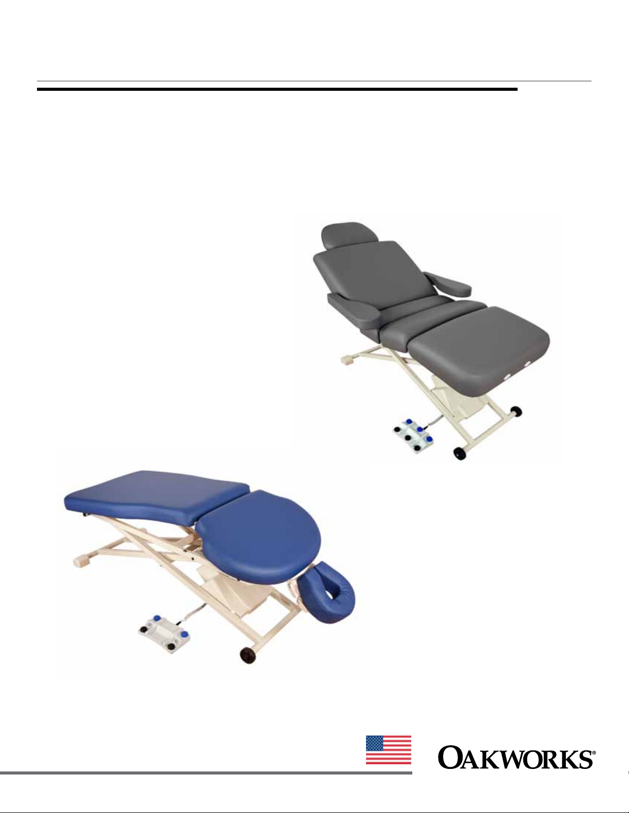
PX & PT Tables
PT Series
made in the USA
with US & imported parts
PX Series
www.oakworksmed.com · 717.235.6807

© Copyright 2013
Oakworks® , Inc.
Printed in U.S.A.
All rights are reserved. No part
of this document may be
photocopied, reproduced or
translated to another language
without prior written consent
akworks
of O
O
akworks
trademark of O
®
, Inc.
®
is a registered
akworks
®
, Inc.
Notice
The information contained in this
document is subject to change
without notice and should not
be construed as a commitment by
O
akworks
®
, Inc.
Oakworks®, Inc. assumes no
responsibility for any errors that
may appear in this document nor
does it make expressed or implied
warranty of any kind with regard
to this material, including, but not
limited to, the implied warranties
of merchantability and fitness for
a particular purpose.
Oakworks®, Inc. shall not be liable
for incidental or consequential
damages in connection with or
arising out of the furnishing,
performance, or use of this
document and the program
material which it describes.

TABLE OF CONTENTS
Product Use Description .....................................................................................................1
Important Safety Instructions
Symbol Identification .................................................................................................... 1
Safety Instructions .....................................................................................................1-2
Product Description & Photo
PX100 ..............................................................................................................................3
PX150 ..............................................................................................................................4
PX300 ..............................................................................................................................5
PT100 ..............................................................................................................................6
PT150 ..............................................................................................................................7
PT200 ..............................................................................................................................8
PT250 ..............................................................................................................................9
PT300 ............................................................................................................................10
PT400 ............................................................................................................................11
PT400M ........................................................................................................................ 12
Orthopedic Hi-Lo Casting Table ................................................................................ 13
Installation
Grounding .................................................................................................................... 14
Directions for Use
Control Operations
All Tables Except - PT400, PT400M & PX300 .................................................. 15
PT400 & PT400M .......................................................................................... 16-17
PX300 ............................................................................................................. 18-19
Adjusting the Back Rest ............................................................................................. 20
Optimal Positioning for PT400 Tables ...................................................................... 20
Articulating Head Rest Use ....................................................................................... 21
Side Rails Use ............................................................................................................. 21
PT400M - Rotating Arm Rests Use ........................................................................... 22
PT400M - Removable Extension Pad Use ................................................................. 22
Moving the table ..........................................................................................................23
Dual Locking Casters Use .......................................................................................... 23
Table Extender Use .................................................................................................... 24
QuickLock Face Rest Use ........................................................................................... 24
Adjustable Arm Rest Installation and Adjustment ................................................. 25
Cleaning & Disinfection ................................................................................................... 26
Inspections & Maintenance ............................................................................................ 26
Warranty Information ........................................................................................................ 26
Model Number & Serial Number
PX Series ....................................................................................................................... 27
PT Series ....................................................................................................................... 28
Specifications
Product Specifications ................................................................................................ 29
Environmental Conditions ........................................................................................ 29
Electrical Specifications ............................................................................................. 29
Guidance and manufacturer’s declaration -
Electromagnetic emissions......................................................................................... 30
Recommended separation distances ......................................................................... 30
Guidance and manufacturer’s declaration -
Electromagnetic immunity ................................................................................... 31-32
Contact Information ......................................................................................... back cover
PRODUCT USE DESCRIPTION / IMPORTANT SAFETY INSTRUCTIONS
PRODUCT USE DESCRIPTION
The Oakworks PX & PT Tables are used to support the patient during examinations and procedures.
They are intended to be operated by a healthcare professional in a medical environment. No special
training is required but a review of the following Safety Instructions is important for the safety of
the operator and patient. The healthcare professional should read and understand this entire manual
before use with a patient. There are no known contradictions to the use of this equipment.
SYMBOL IDENTIFICATION
This symbol, when used in this manual and on product labels, represents a caution
warning. Be sure to read and comply with all precautions and warnings.
This symbol, when used in this manual and on product labels, warns against an
electrical shock hazard. Be sure to observe and comply with all warnings.
This symbol, when used in this manual or on product labels, indicates a Protective Earth
(Ground) Terminal.
This symbol, when used in this manual and on product labels, indicates that the table
and components are a Type B Applied Part pursuant to IEC 60601-1: 2005.
This symbol, when used in documentation on this product, indicates alternating
~
----
current (AC).
This symbol, when used in documentation on this product, indicates direct current
(DC).
This symbol is used to indicate that the operator should consult the user manual.
IMPORTANT SAFETY INSTRUCTIONS
CAUTION
The use of accessories, transducers, and cables other than those specified by the manufacturer, may result in increased emissions or
decreased immunity of the table.
The Table should not be used adjacent to or stacked with other equipment and that if adjacent or stacked use is necessary, the table should
be observed to verify normal operation in the configuration in which it will be used.
The Table is designed to be a stand-alone table. This table must not be modified or incorporated into any other equipment.
As with any moving mechanism there are potential pinch points around and underneath the table. It is the responsibility
of the operator of this equipment to insure that bystanders are not in the area below or around this equipment during operation.
Proper operation of this equipment is very important for the safety of the operator, patient, and any other individuals in the
area of this equipment. Directions for use of this equipment are described in this manual. The operator should read these sections
carefully.
READ AND SAVE THESE INSTRUCTIONS
1

IMPORTANT SAFETY INSTRUCTIONS
Weight Limit: (patient and accessories) 550 lbs. (250 kg) Do not exceed.
The Back Rest and Leg Rest sections are not designed to support the entire weight of the patient. Do not sit on
the Back Rest or Leg rest sections.
Be certain that the table is completely lowered without any tilt being present prior to discharging an ambulatory
patient. The patient may lose balance and fall.
This table is not suitable for use in the presence of flammable anesthetic mixture with air or oxygen or nitrous oxide.
Do not lift table by the table top. This can damage the table.
When lowering the table, make sure there is nothing underneath the table top that can impede motion (like stools, cabinets, accessory parts, cleaners, etc)
Use this furnishing only for its intended use as described in these instructions. Do not use attachments not recommended by the manufacturer.
Close supervision is necessary when this furnishing is used near children or disabled persons.
WARNING
To reduce the risk of burns, fire, electric shock or injury to persons:
1. Unplug this furnishing from the electrical outlet before cleaning.
2. Unplug from outlet before adding or removing parts.
3. Never operate this furnishing if it has a damaged cord or plug, if it is not working properly, if it has been dropped
or
damaged, or dropped into water. Contact Oakworks Customer Service before use.
4. Keep the cord away from heated surfaces.
5. Never drop or insert any object into any opening.
6. Do not use outdoors.
7. Do not operate where aerosol (spray) products are being used or where oxygen is being administered.
DANGER
Risk of electric shock - Connect this furnishing to a properly grounded outlet only. See Grounding Instructions in
this manual.
Electrical Shock Hazard. The power supply/control module is located under the table seat. No user serviceable parts
are inside the control box. Refer servicing to qualified personnel. Unplug wall plug prior to contact with any cables
connected to the power supply.
2
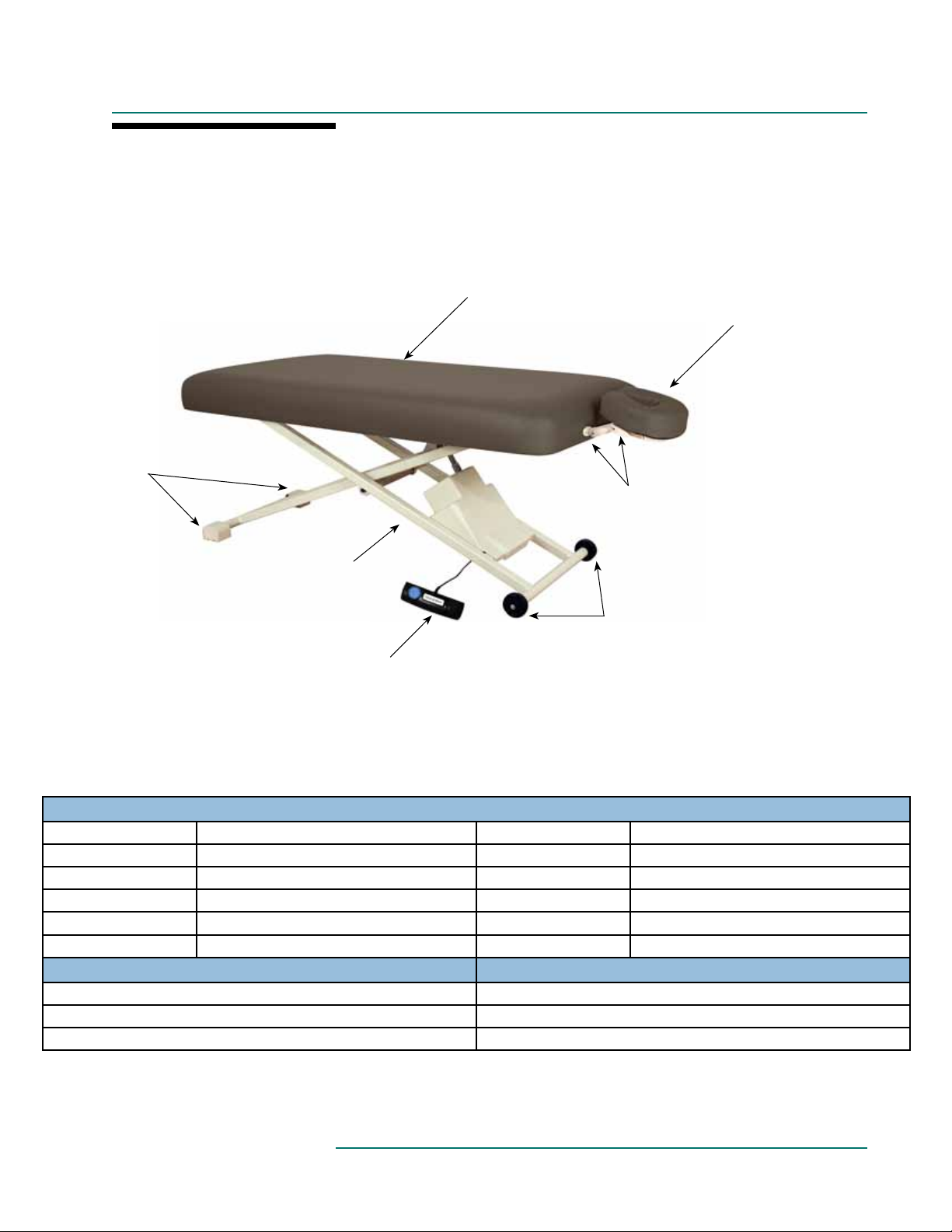
PRODUCT DESCRIPTION
PX100
Self-locking
molded rubber
feet (2)
Upholstered Top
QuickLock™ Face
rest with Boiance™
Crescent
Accessory attachment
outlets
Steel Scissor-style
powder-coated base
with dual crossbeams (1)
Wheels (2)
Foot Control
STANDARD SPECIFICATIONS
Height Range Powered 18”-35” (46-89 cm.) Length 73” (185 cm.)
Foot Control Height Motion Padding 3” (8 cm.) Comfort Foam
Table Voltage Options 120V/60Hz or 230V/50Hz Upholstery Terra Touch
Table Capacity 550 lbs. (250 kg.) (patient and accessories) Table Weight
*
170 lbs. (70 kg.)
™
Widths 29” (74 cm.) or 31” (79 cm.) Warranty 3 year parts, 1 year labor
Safety Listings FDA, cETLus, CE marked
OPTIONS ACCESSORIES
Dual Locking Casters QuickLock Face Rest
2 Button Hand Control Table Extender
Second Foot Control
For electrical specs, see Specifications section.
3
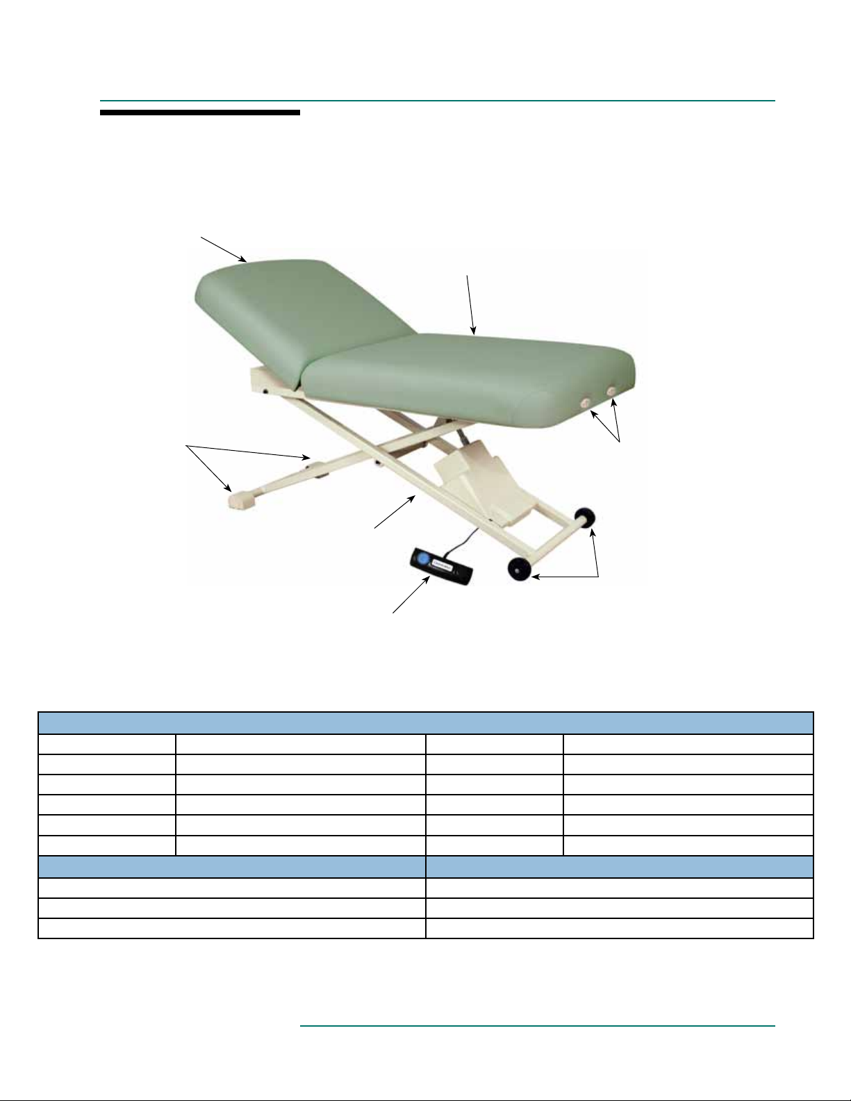
PRODUCT DESCRIPTION
PX150
Manual Lift-Assist
Back Rest control
Self-locking
molded rubber
feet (2)
Upholstered Top
Accessory attachment
outlets
Steel Scissor-style
powder-coated base
with dual crossbeams (1)
Wheels (2)
Foot Control
STANDARD SPECIFICATIONS
Motion 1 Powered 21”-38” (55-97 cm.) Height Range Length 73” (185 cm.)
Motion 2 Manual 0º - 79º Backrest Padding 3” (8 cm.) Comfort Foam
Foot Control Height Motion Upholstery Terra Touch
Table Voltage Options 120V/60Hz or 230V/50Hz Table Weight
*
170 lbs. (70 kg.)
™
Table Capacity 550 lbs. (250 kg.) (patient and accessories) Warranty 3 year parts, 1 year labor
Widths 29” (74 cm.) or 31” (79 cm.) Safety Listings FDA, cETLus, CE marked
OPTIONS ACCESSORIES
Dual Locking Casters QuickLock Face Rest
2 Button Hand Control Table Extender
Second Foot Control
For electrical specs, see Specifications section.
4
PRODUCT DESCRIPTION
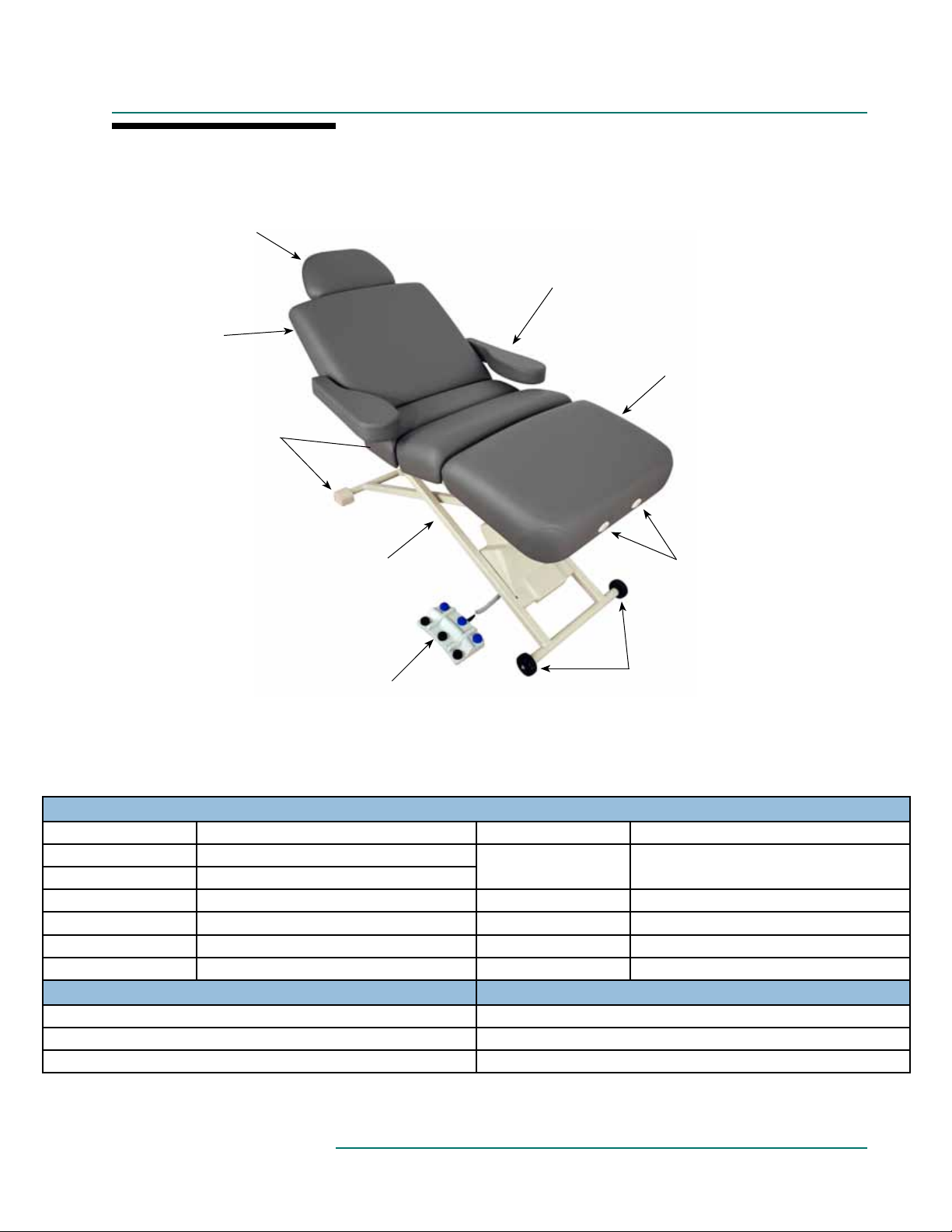
PX300
Table Extender
(accessory)
Manual Lift-Assist
Back Rest control
Self-locking
molded rubber
feet (2)
Adjustable
Arm Rests (2)
(accessory)
Upholstered Top
Steel Scissor-style
powder-coated base
with dual crossbeams (1)
Multi-function
Foot Control
Accessory attachment
outlets
Wheels (2)
STANDARD SPECIFICATIONS
Motion 1 Powered 21”-38” (55-97 cm.) Height Range Motion 3 Powered 0º - 51º Thigh / 0º - 19º Footrest
Motion 2 Powered 0º - 53º Backrest
Table Voltage Options 120V/60Hz or 230V/50Hz
Table Capacity 550 lbs. (250 kg.) (patient and accessories) Upholstery Terra Touch
Widths 29” (74 cm.) or 31” (79 cm.) Table Weight
Multi-function Foot
Control
*
All powered motions
™
202 lbs. (92 kg.)
Length 73” (185 cm.) Warranty 3 year parts, 1 year labor
Padding 4” (10 cm.) Comfort Foam Safety Listings FDA, cETLus, CE marked
OPTIONS ACCESSORIES
Dual Locking Casters QuickLock Face Rest
6 Button Hand Control Table Extender
Adjustable Side Arm Rests
For electrical specs, see Specifications section.
5
Wheels (2)
Foot Control
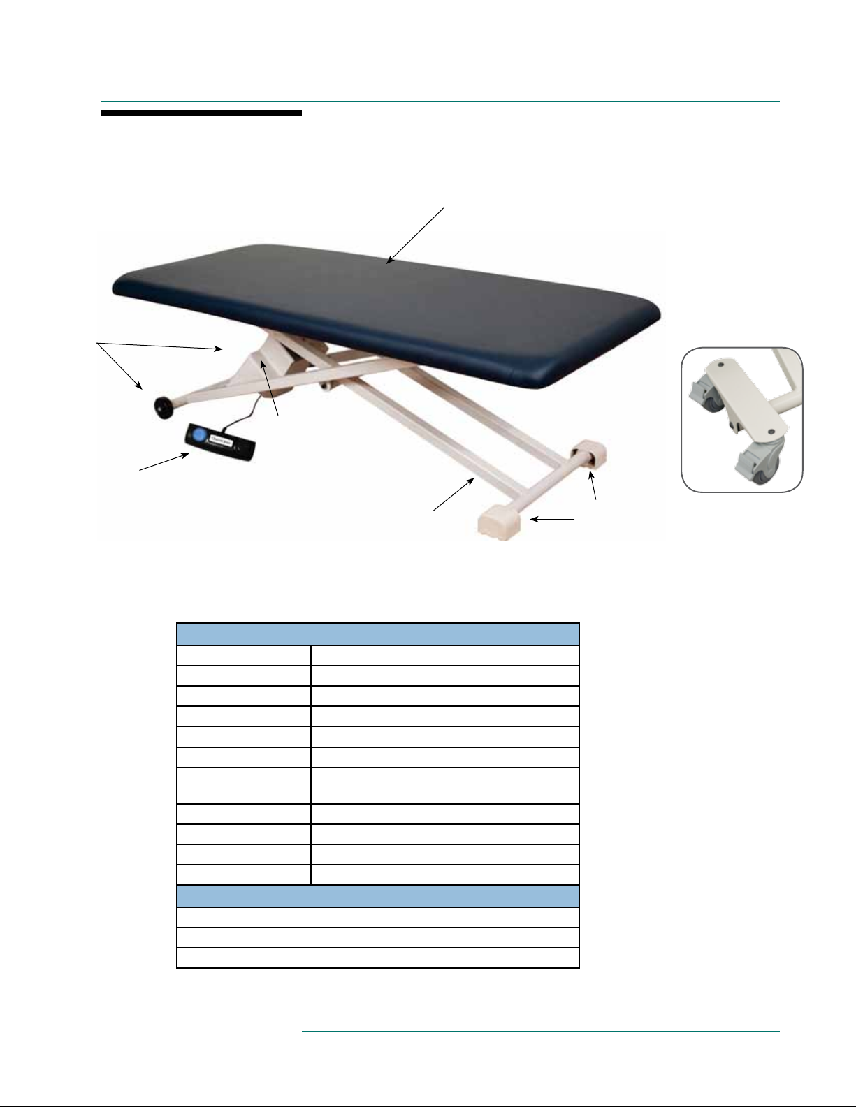
PRODUCT DESCRIPTION
PT100
Upholstered Top
Single 24v motor
with cover
Steel Scissor-style
powder-coated base
with dual crossbeams (1)
STANDARD SPECIFICATIONS
Height Range Powered 16”-34” (40-86 cm.)
Foot Control Height Motion
Table Voltage Options 120V/60Hz or 230V/50Hz
Table Capacity 550 lbs. (250 kg.) (patient and accessories)
Widths 27” (69 cm.) or 29” (74 cm.)
Length 73” (185 cm.)
Padding
1.75” (4.4 cm.) Firm Response
2.5” (6.4 cm.) Comfort Foam
Upholstery Terra Touch
Table Weight
*
155 lbs. (70 kg.)
™
OR
Warranty 3 year parts, 1 year labor
Safety Listings FDA, cETLus, CE marked
OPTIONS
Dual Locking Casters
2 Button Hand Control
Second Foot Control
Self-locking
molded rubber
feet (2)
Optional Dual
Locking Casters
For electrical specs, see Specifications section.
6
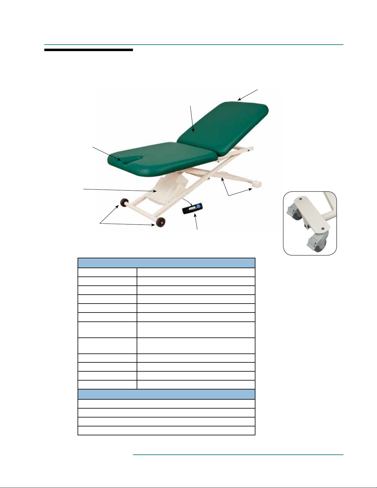
PRODUCT DESCRIPTION
PT150
Seat section with
Integrated Face
Rest
Single 24v Motor
with cover
Wheels (2)
Manual Lift-Assist
Back Rest control
Upholstered Top
Steel Scissor-style
powder-coated base
with dual crossbeams (1)
Self-locking
molded rubber
feet (2)
Foot Control
STANDARD SPECIFICATIONS
Motion 1 Powered 16”-34” (40-86 cm.) Height Range
Motion 2 Manual 0º - 90º Fowler Backrest
Foot Control Height Motion
Table Voltage Options 120V/60Hz or 230V/50Hz
Table Capacity 550 lbs. (250 kg.) (patient and accessories)
Widths 29” (74 cm.) or 31” (79 cm.)
Length - 2 Section top
Padding
Upholstery Terra Touch
Table Weight
*
39” (99 cm.) Backrest section
36” (92 cm.) Seat section
1.75” (4.4 cm.) Firm Response
2.5” (6.4 cm.) Comfort Foam
™
160 lbs. (73 kg.)
OR
Warranty 3 year parts, 1 year labor
Safety Listings FDA, cETLus, CE marked
OPTIONS
Dual Locking Casters
2 Button Hand Control
Second Foot Control
(1) or (2) Side Rails (31” width only)
Optional Dual
Locking Casters
For electrical specs, see Specifications section.
7
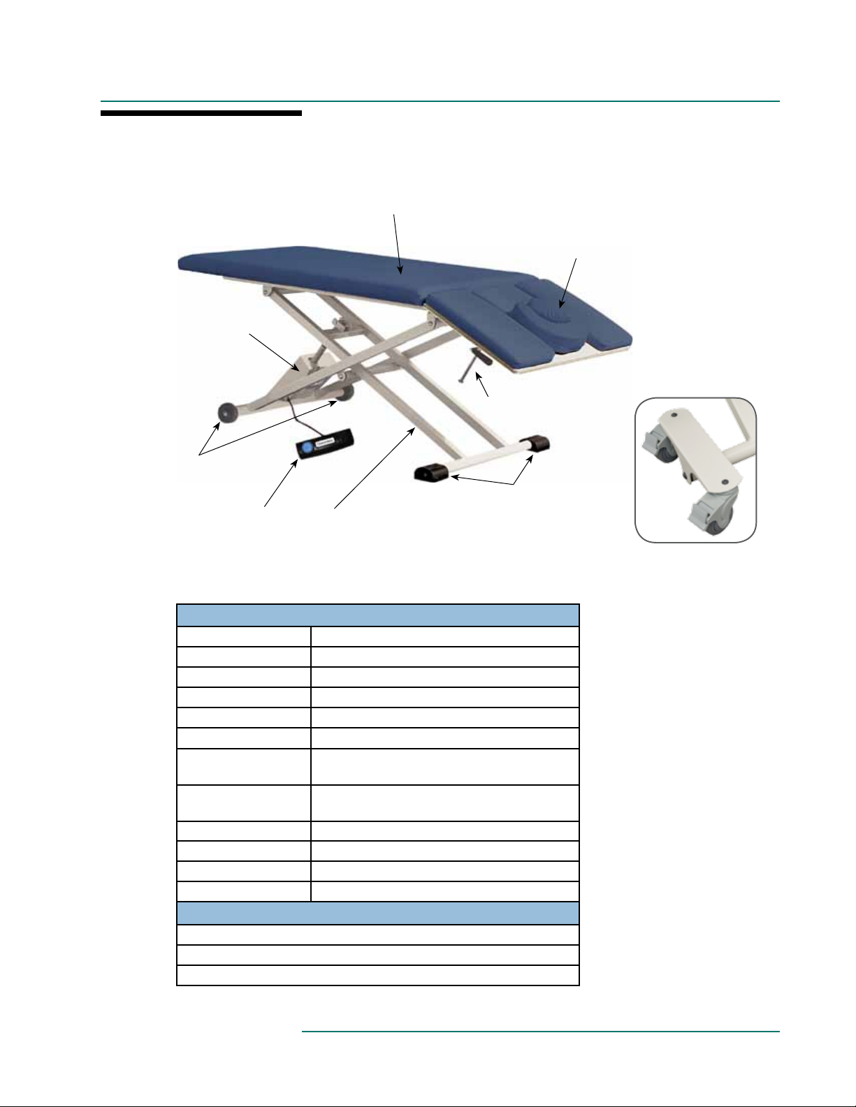
PRODUCT DESCRIPTION
PT200
Single 24v Motor
with cover
Wheels (2)
Foot Control
Upholstered Top
Steel Scissor-style
powder-coated base
with dual crossbeams (1)
Articulating Head Rest
Section with Adjustable
Face Rest Cushion &
Insert Pad
Manual Control for
Back Rest Top
Self-locking
molded rubber
feet (2)
Optional Dual
Locking Casters
STANDARD SPECIFICATIONS
Motion 1 Powered 16”-34” (40-86 cm.) Height Range
Motion 2 Manual 55˚ to -40˚ Articulating Head Rest
Foot Control Height Motion
Table Voltage Options 120V/60Hz or 230V/50Hz
Table Capacity 550 lbs. (250 kg.) (patient and accessories)
Widths 29” (74 cm.)
Length - 2 Section top
Padding
Upholstery Terra Touch
Table Weight
*
58” (147 cm.) Seat section
19” (48 cm.) Head Rest
1.75” (4.4 cm.) Firm Response
2.5” (6.4 cm.) Comfort Foam
™
165 lbs. (75 kg.)
OR
Warranty 3 year parts, 1 year labor
Safety Listings FDA, cETLus, CE marked
OPTIONS
Dual Locking Casters
2 Button Hand Control
Second Foot Control
For electrical specs, see Specifications section.
8

PRODUCT DESCRIPTION
PT250
Self-locking
molded rubber
feet (2)
Upholstered Top
Articulating Head
Rest Section
Optional Dual
Locking Casters
Steel Scissor-style
powder-coated
base with dual
crossbeams (1)
Foot Control
Single 24v motor
with cover
STANDARD SPECIFICATIONS
Motion 1 Powered 16”-34” (40-86 cm.) Height Range
Motion 2 Manual 40˚ to -90˚ Articulating Head Rest
Foot Control Height Motion
Table Voltage Options 120V/60Hz or 230V/50Hz
Table Capacity 550 lbs. (250 kg.) (patient and accessories)
Widths 27”, 29” or 31” (69cm., 74 cm., 79 cm.)
Length - 2 Section top
Padding
Upholstery Terra Touch
Table Weight
*
62” (157 cm.) Seat section
10” (25 cm.) Head Rest
1.75” (4.4 cm.) Firm Response
2.5” (6.4 cm.) Comfort Foam
™
151 lbs. (68 kg.)
OR
Warranty 3 year parts, 1 year labor
Safety Listings FDA, cETLus, CE marked
OPTIONS
Dual Locking Casters
2 Button Hand Control
Second Foot Control
Manual Control for
Articulating Head Rest
Section
Wheels (2)
For electrical specs, see Specifications section.
9

PRODUCT DESCRIPTION
PT300
Manual Lift-Assist
Back Rest control
Optional Dual
Locking Casters
Articulating Head
Rest Section
Steel Scissor-style
powder-coated
base with dual
crossbeams (1)
Foot Control
Single 24v
motor with cover
Manual Control for
Articulating Head Rest
Section
Wheels (2)
STANDARD SPECIFICATIONS
Motion 1 Powered 16”-34” (40-86 cm.) Height Range Motion 3 Manual 40˚ to -90˚ Articulating Head Rest
Motion 2 Manual 0º - 90º Fowler Backrest Foot Control Height Motion
Padding
1.75” (4.4 cm.) Firm Response
2.5” (6.4 cm.) Comfort Foam
OR
Table Voltage Options 120V/60Hz or 230V/50Hz
Table Capacity 550 lbs. (250 kg.) (patient and accessories)
Upholstery Terra Touch
Table Weight
*
160 lbs. (73 kg.) Safety Listings FDA, cETLus, CE marked
™ Warranty 3 year parts, 1 year labor
Widths 27”, 29” or 31” (69cm., 74 cm., 79 cm.)
39” (99 cm.) Fowler Backrest
Length - 3 Section top
23” (28 cm.) Seat section
10” (25 cm.) Head Rest
OPTIONS
Dual Locking Casters Second Foot Control
2 Button Hand Control (1) or (2) Side Rails (31” width only)
For electrical specs, see Specifications section.
10

PRODUCT DESCRIPTION
PT400
Manual Lift-Assist
Back Rest control
Electrically Controlled
Center Break
24v motor
Optional Dual
Locking Casters
Steel Scissor-style
powder-coated
base with dual
crossbeams (1)
Foot Control
Single 24v
motor with cover
Manual Control for
Articulating Head Rest
Section
Wheels (2)
Articulating Head
Rest Section
STANDARD SPECIFICATIONS
Motion 1 Powered 17”-34” (43-86 cm.) Height Range Motion 3 Manual 0º - 82º Fowler Backrest
Motion 2 Powered 0˚ to 26˚ Center Break Motion 4 Manual 47˚ to -92˚ Articulating Head Rest
Padding
1.75” (4.4 cm.) Firm Response
2.5” (6.4 cm.) Comfort Foam
Foot Control All powered motions
Table Voltage Options 120V/60Hz or 230V/50Hz
OR
Widths 27”, 29” or 31” (69cm., 74 cm., 79 cm.)
38” (97 cm.) Fowler Backrest
Length - 3 Section top
22” (56 cm.) Seat section
10” (25 cm.) Head Rest
Table Capacity 550 lbs. (250 kg.) (patient and accessories) Warranty 3 year parts, 1 year labor
Upholstery Terra Touch
Table Weight
*
198 lbs. (90 kg.)
™ Safety Listings FDA, cETLus, CE marked
OPTIONS
Dual Locking Casters 2 Button Hand Control
For electrical specs, see Specifications section.
11

PRODUCT DESCRIPTION
16.25”
(41 cm.)
4.5”
(11 cm.)
PT400M
29.5”
(75 cm.)
11”
(29 cm.)
22” (56 cm.)
21.5”
(55 cm.)
44.5”
(113 cm.)
Self-locking
molded rubber
feet (2)
77”
(196 cm.)
Steel Scissor-style
powder-coated
base with dual
crossbeams (1)
Foot Control
Electrically Controlled
Center Break
QuickLock Platform & Boiance
Face Pad
Wheels (2)
Single 24v
motor with cover
Optional Dual
Shown with accessories;
Rotating Arm Rests & Extension Pad
Locking Casters
STANDARD SPECIFICATIONS
Motion 1 Powered 17”-34” (43-86 cm.) Height Range Motion 3 Manual 0º - 82º Foot Section
Motion 2 Powered 0˚ to 15˚ Center Break Foot Control All powered motions
Widths 29.5” (75 cm.)
Length - Contoured
3 Section top
*
44.5” (113 cm.) Foot end
21.5” (55 cm.) Middle section
11” (29 cm.) Head Rest
186 lbs. (84 kg.)
Padding
1.75” (4.4 cm.) Firm Response
2.5” (6.4 cm.) Comfort Foam
OR
OR
4” (10 cm.) Comfort Foam
Table Voltage Options 120V/60Hz or 230V/50Hz
Table Capacity 550 lbs. (250 kg.) (patient and accessories) Table Weight
Upholstery Terra Touch
QuickLock Platform &
Boiance Face Pad
for both prone and supine positioning Safety Listings FDA, cETLus, CE marked
™ Warranty 3 year parts, 1 year labor
OPTIONS ACCESSORIES
Dual Locking Casters PT400M - Rotating Arm Rests (2)
Hand Control - 4 Button PT400M - Shelf Bracket
Second Foot Control PT400M - Extension Pad
For electrical specs, see Specifications section.
12

PRODUCT DESCRIPTION
Orthopedic Hi-Lo Casting Table
Gas Assist Control
for Backrest
Upholstered Top
Retractable
side rail
Self-locking
molded rubber
feet (2)
Optional Dual
Locking Casters
Steel Scissor-style
powder-coated base
with dual crossbeams (1)
Foot Control
STANDARD SPECIFICATIONS
Motion 1 Powered 17”-35” (43-89 cm.) Height Range
Motion 2 Manual 0º - 90º Fowler Backrest
Padding
1.75” (4.4 cm.) Firm Response
2.5” (6.4 cm.) Comfort Foam
OR
Table Voltage Options 120V/60Hz or 230V/50Hz
Table Capacity 550 lbs. (250 kg.) (patient and accessories)
Upholstery Terra Touch
Table Weight
(1) Side Rail (specify
side location)
*
165 lbs. (75 kg.) Warranty 3 year parts, 1 year labor
for extra security and stability for patients Safety Listings FDA, cETLus, CE marked
™
Motion 3
Foot Control Height Motion
Widths 31” (79 cm.)
Length - 3 Section top
OPTIONS
Dual Locking Casters Second Side Rail
Hand Control
Resin casting
cover
Manual Control for
Articulating Casting
Section
Single 24v motor
with cover
Wheels (2)
Manual 10˚ to -90˚ Articulating Casting
Section
38” (97 cm.) Fowler Backrest
22” (56 cm.) Seat section
10” (25 cm.) Casting section
For electrical specs, see Specifications section.
13

INSTALLATION
The Tables come completely assembled and ready to use. Plug the cord into a functioning outlet that is
rated for the table. (see Grounding below)
Arrange the power cord and control cords so that they will not create a tripping hazard and where
the controls are located to your liking and are conveniently accessible.
Be sure access to plug is not blocked for disconnecting the table from power.
GROUNDING
DANGER
This product must be grounded. If it should malfunction or break down, grounding
provides a path of least resistance for electrical current to reduce the risk of electric
shock. This product is equipped with a cord having an equipment-grounding conductor
and a grounding pin. The pin must be plugged into an appropriate outlet that is properly installed and grounded in accordance with all local codes and ordinances. See U.S.
sample below.
Improper connection of the equipment-grounding conductor can result in a risk of electric shock. Check with a qualified electrician or service person if you are in doubt as to
whether the product is properly grounded. Do not modify the plug provided with the
product - if it will not fit the outlet; have a proper outlet installed by a qualified electrician.
Risk of Electric Shock - Connect this furnishing to a properly grounded outlet only.
Grounding Methods
Correct Implementation
Incorrect Implementation
14

DIRECTIONS FOR USE
CONTROL OPERATIONS - ALL TABLES
EXCEPT PX300, PT400 & PT400M)
CAUTION
Be sure the self-locking molded rubber feet are flat side down to ensure safety and stability.
The tables
Control as shown below to raise or lower the height of the table.
offer height positioning with electronic ease. Operate the Foot control and Optional Hand
FOOT CONTROL OPERATION
UP
DOWN
HAND CONTROL OPERATION (OPTIONAL)
UP
DOWN
15

DIRECTIONS FOR USE
FOOT CONTROL OPERATIONS - PT400 & PT400M TABLES ONLY
CAUTION
The O
akworks
Operate the Foot control as shown below to raise or lower the height and center break functions of
the table.
Center Break
®
PT400 and PT400M tables offer height and center break positioning with electronic ease.
UP
DO NOT sit or stand on the articulating head rest section. Be sure the self-locking molded
rubber feet are flat side down to ensure safety and stability.
Height UP
Center Break
DOWN
Height DOWN
16

DIRECTIONS FOR USE
HAND CONTROL OPERATIONS - PT400 & PT400M TABLES ONLY
CAUTION
The O
akworks
Operate the Optional Hoot control as shown below to raise or lower the height and center break
functions of the table.
Center Break
®
PT400 and PT400M tables offer height and center break positioning with electronic ease.
UP
DO NOT sit or stand on the articulating head rest section. Be sure the self-locking molded
rubber feet are flat side down to ensure safety and stability.
Center Break
DOWN
Height DOWNHeight UP
17

DIRECTIONS FOR USE
FOOT CONTROL OPERATIONS - PX300 TABLES ONLY
CAUTION
The Oakworks® PX300 tables offer height, backrest and footrest positioning with electronic ease. Operate
the Foot control as shown below to raise or lower the height, backrest or footrest functions of the
table.
Do not sit backrest ot leg rest sections. Be sure the self-locking molded rubber feet are flat side down
to ensure safety and stability. The hood area under the backrest top is not designed for storage. DO
NOT use this area for holding anything. Damage can occur to the table.
Footrest UP
Height UP
Backrest UP
Height DOWN
Backrest DOWN
Footrest DOWN
18

DIRECTIONS FOR USE
HAND CONTROL OPERATIONS - PX300 TABLES ONLY
CAUTION
The Oakworks® PX300 tables offer height, backrest and footrest positioning with electronic ease. Operate
the Optional Hand control as shown below to raise or lower the height, backrest or footrest functions
of the table.
Do not sit backrest ot leg rest sections. Be sure the self-locking molded rubber feet are flat side down
to ensure safety and stability. The hood area under the backrest top is not designed for storage. Do
not use this area for holding anything. Damage can occur to the table.
Height UP Height DOWN
Footrest UP
Backrest UP
Footrest DOWN
Backrest DOWN
19

DIRECTIONS FOR USE
ADJUSTING THE BACK REST SECTION
CAUTION
Do not sit on the Backrest section.
TO RAISE THE BACK REST
Raise the back rest by pressing the lever
under the head section and lifting up to the
desired height. It is recommended that clients
take some of their weight off the back rest
while you lift.
OPTIMAL POSITIONING FOR PT400 TABLES
Dr. Robert DuVall demonstrates the features of the PT400 table.
Back Rest
Control
TO LOWER THE BACK REST:
Press the lever under the head section and
push the back rest down.
PX150 TABLES ONLY
TO CHANGE LEVER POSITION:
The back rest lever can be moved to the
opposite side of the back rest by removing
the screws and relocating the hand lever to
the opposite side of the top into the four predrilled holes.
Posterior pelvic tilt
Scan this QR code with
your smartphone or visit
www.oakworksmed.com
to view the PT400 video.
Watch the
video!
Dr. Robert DuVall,
PT, DHSc, ATC, OCS, SCS, FAAOMPT CSCS
At the Oakworks® factory in PA
reviewing the Oakworks® PT400.
Side bend to
elongate the
quadratus
lumborum
20

DIRECTIONS FOR USE
ARTICULATING HEAD REST USE
CAUTION
assisting the client on or off the table.
Grasp Firmly
& Lift
TO RAISE THE HEAD REST
Do not sit or stand on the articulating head rest section. Do not use Head Rest Section in
Grasp the edge of the section and lift up until you
have achieved the angle needed. Release and it will
lock into place automatically.
SIDE RAIL USE
Release Knob
TO LOWER THE HEAD REST:
Twist and hold the knob under the head rest and
push the head rest down. Release the knob and the
head rest will stay in place.
TO LOWER SIDE RAILS
Push side rail in lightly towards the center of the table,
then push locking knob down towards the table base.
Fold side rails down and under the table.
TO RAISE SIDE RAILS
Grasp side rail and rotate to the raised position. When
fully up, the side rail will lock into position. Check that
the rail is locked by applying light outward pressure.
21

DIRECTIONS FOR USE
PT400M - ROTATING ARM RESTS USE
Be sure to install the arm rest on the
correct side of the table. The arm rest
will contour to the table top as shown.
PT400M - REMOVABLE EXTENSION PAD USE
Extension Pad Used as a Lowered Arm Rest
Screw the Extension
Pad Attachment Bracket
it into the head end of
the table using the predrilled hole. Be sure
to angle the bracket as
shown above.
Insert the Extension Pad
dowels into the bracket.
Screw the Arm Rests into the predrilled hole on the under side of each
side of the table.
Insert the QuickLock™ Face
Rest platform dowels into the
Accessory Mounting Plate that is
attached to the table.
Adjust the Arm Rests as needed for
support and patient access.
Adjust the Face Rest and
Pad as needed.
Extension Pad Used as a Table Extender
Insert Extension Pad dowels into the Accessory Mounting Plate located at either end of table.
22

DIRECTIONS FOR USE
MOVING THE TABLE
CAUTION
The tables are equipped with two wheels at one end and two self-locking, molded rubber feet at the
other. When ready to move the table, first lower the table to its lowest position. On models with a back
rest, it is recommended to raise the back rest to a high position. Then be sure the power source is
disconnected. Place the cord & all controls out of the way on top of your table before moving the table.
Lay a towel or a cloth down on your table top to protect the surface from any debris from the bottom of your
foot control.
Two people are required to safely move the table. Grasp the table frame securely at the end with
the molded rubber feet. Raise the table to allow the wheels at the foot end to move freely. Bending at
the knees before lifting to prevent back strain or possible injury.
Before moving any of the Tables, disconnect the power cord from the power outlet. The
table weighs as much as 200 lbs. (91 kg.) Use extreme caution when lifting the table to
move it. Two people are required to move the table safely. DO NOT use the table to
transport a patient.
Grasp the
table frame
securely here
at both sides
of the brace.
Move the table carefully to the next location, lower the table and release. Check the self-locking
molded rubber feet to be sure they are flat side down. This position “locks” the table and allows sturdy
height adjustments. Place the foot controls in position on the floor. Connect the power cord to the outlet
and test the foot control.
DUAL LOCKING CASTERS USE
All casters should be locked at all times during use with a patient.
LOCKING THE CASTERS
1. Place your shoe on the end of the casters locking tab.
2. Press firmly downward until you here a clicking noise
and the caster is locked.
UN-LOCKING THE CASTERS
1. Place your shoe on top of the casters locking tab.
2. Press firmly inward and downward until you here a clicking noise and the caster is unlocked.
23

DIRECTIONS FOR USE
TABLE EXTENDER USE
CAUTION
Do not put excessive weight or pressure on the table extender.
The Table Extender lengthens
the table for your tallest clients
and can improve access to your
patient.
Accessory
attachment
outlets
Locate the Accessory attachment outlets.
QUICKLOCK FACE REST
Insert the Table Extender
tubes.
* U.S. Patent #5,177,823
Do not put excessive weight or pressure on the Quicklock Face Rest. Do not extend the
CAUTION
Double articulating action provides nearly limitless positioning options with the QuickLock
dowels of the Quicklock Face Rest 3” (7.6 cm.) from the Fowler (Backrest) section.
™ Face
Rest. The adjustable pad takes pressure off sensitive facial areas while providing superb support. The
QuickLock™ Face Rest can be used in both prone and supine positioning and folds out of the way
when not in use. Adjustments are made easily by loosening the cam locks, adjusting for height and
angle and then locking the cam locks into the desired position.
Insert dowels into
Accessory attachment outlets.
Accessory
attachment
outlets
Loosen Cam Locks &
adjust face rest into place.
QuickLock™
Face Rest
Tighten the Cam Locks.
Important Safety Note:
Maximum Distance from edge
of Table = 3” (7.6 cm.)
The Face Rest can be used
for either prone or supine
positioning.
24

DIRECTIONS FOR USE
ADJUSTABLE ARM REST INSTALLATION AND ADJUSTMENT
CAUTION
TO INSTALL THE ARM RESTS:
The Arm Rests adjust automatically as the back rest moves to remain parallel to the floor.
1. Insert end of arm rest into backrest hole while holding the arm
rest at a 60° angle to the backrest.
TO LEVEL THE ARM RESTS:
The Arm Rest height is adjusted at the factory for each table. If the armrest starts to sag with repeated use,
follow the steps below to readjust.
Do not use the arm rest for patient support during the mounting or dismounting of the chair.
The arm rest is not designed to support the patient’s weight.
2. Push end all the way into the hole and drop the arm rest into the horizontal
position. Pull outward to make sure the arm rest is secure.
1. Loosen the bottom 2 set
screws.
2. Turn the side set screw
(clockwise to raise or counterclockwise to lower) while
adjusting the arm rest. Lift the
arm rest slightly when doing
this adjustment to reduce the
weight.
3. Tighten the two bottom set
screws to lock the position.
25

CLEANING & DISINFECTION / INSPECTIONS / WARRANTY
CLEANING & DISINFECTION
WARNING
Use a 10% sodium hypochlorite (bleach) solution or Recommended Disinfectants on all surfaces. Clean all sides
of each upholstered section. Follow the directions on the disinfectant and wipe off excess.
Recommended Disinfectants
Protex, MadaCide, Accell TB, Virox®
Before cleaning with any liquid cleaner be sure to unplug the power cord from the outlet.
Note: Damage caused by unapproved substances will not be covered under the warranty.
DO NOT use citrus based cleaners or other strong cleaners, such as alcohol, acetone, higher concentrations of
bleach or other products that contain high concentrations of these substances.
DO NOT expose the fabric to temperatures below 50°F/10°C or above 104°F/40°C.
DO NOT expose the fabric to direct sunlight, adhesives, liquids, or abrasive materials.
INSPECTIONS & MAINTENANCE
RECOMMENDED REGULAR INSPECTIONS (monthly or local standard)
• Check for damage to the power, hand control or foot control cables.
• Visually inspect components for obvious damage that could cause problems during operation.
RECOMMENDED PERIODIC INSPECTIONS (yearly or local standard)
• Check for damage to the power, hands control or foot control cables and all visible wiring.
• Visually inspect components for obvious damage that could cause problems during operation.
• Check all mechanical functions using the hand control. Repeat using the foot control. Check for abnormal
noises.
• Replace any missing or illegible labels.
• Check that all fasteners are present and fastened securely.
• Check table grounding.
• Clean unusual buildup of dirt on the chair and/or parts of the chair not normally cleaned on a regular
basis.
• Check for tears or cracks in the upholstery.
MAINTENANCE
• No specific maintenance tasks are required.
• Oakworks medical tables/chairs are designed and built to provide many years of dependable service.
Please follow local regulations and laws when disposing of the electrical components used in this chair.
•
For all Customer Service related problems refer to the Service Manual
WARRANTY
View complete warranty details at www.oakworks.com
26

MODEL NUMBER & SERIAL NUMBER
PX SERIES
16796025 PXEXFT311873ACTTVN Ser#: PXR563146
PX FT 30 x 22-38 x 72 3M/TT/2S
TTSKYBLUE 01/04/2013 Order#:654321
Notes: Sample Product Label
The model number and serial
number are located on the
underside of the foot section.
MODEL NUMBER DESCRIPTION
PX EX FT XX XX XX AC TT VN F6
Model Number
Serial Number
Model Numbers and
Serial Numbers always
start with a letter.
Options - May be in any order.
EU = Europe
F6 = 3 Motion Foot Control
H6 = 3 Motion Hand Control
CS = Casters
Grommet:
VN = Vanilla
BK = Black
Fabric:
TT = TerraTouch
Padding:
AC = AeroCel 4”
A6 = AeroCel 6”
PL = Plush
SF = SemiFirm
FM = Firm
Table Top Length
Minimum Table Height
Table Top Width
Top:
FT = Flat
BR = Lift-Assist Backrest
LS = Lift Assist Salon
ES = Electric Salon
Base:
EX = Medical Table
Table Model:
PX = PX Series
27

MODEL NUMBER & SERIAL NUMBER
PT SERIES
16796025 PXSLA3311873ACTTVN Ser#: PXR563146
US G2 30 x 22-38 x 72 3M/TT/2S
TTSKYBLUE 01/04/2013 Order#:654321
Notes: Sample Product Label
The model number and serial
number are located on the
underside of the foot section.
MODEL NUMBER DESCRIPTION
PX SL A3 XX XX XX FR TT XX PT CS
Model Number
Serial Number
Model Numbers and
Serial Numbers always
start with a letter.
Options - May be in any order.
EU = Europe
TH = Thailand
SA = Saudi Arabia
CH = Switzerland
CS = Casters
SR = One Side Rail
2R = Two Side Rails
H2 = 2 Motion Hand Control
2H = 2 Hand Controls
OC= Hi-Lo Casting
PT Line
Grommet: Not Applicable
Fabric:
TT = TerraTouch
Padding:
FR = Firm Response
MG = 2.5” Comfort Foam
Table Top Length
Minimum Table Height
Table Top Width
Top:
FT = PT100
A7 = PT150
AB = PT200
A5 = PT250
A3 = PT300
A4 = PT400
A6 = PT400M
Base:
SL = Scissor Lift
Table Model:
PX = Physical Therapy
28

SPECIFICATIONS
PRODUCT SPECIFICATIONS
Table Weights:
Shipping Weights:
Lifting Capacity
151-202 lbs. (68-92 kg.)
236-287 lbs. (107-130 kg.)
550 lbs. (250 kg.)
ENVIRONMENTAL CONDITIONS
Conditions Temperature Humidity Atmospheric Pressure
Normal Use 50° (10°C) to 104° (40°C) 20% to 60% RH 98 to 105 kPa
Storage & Transport -20° (-29°C) to 135° (57°C) 20% to 95% RH 98 to 105 kPa
ELECTRICAL SPECIFICATIONS
Designed for: North America Europe Japan
Input Service 120 VAC/15 amp/60 Hz 230 VAC/10 amp/50/60 Hz 100 VAC/15 amp/50 Hz
Current Draw 2.7 amps 1.5 amps 3.3 amps
Maximum Momentary
Current Consumption
Voltage Output to
Actuators
Electric Shock
Protection
Tabletop Applied Part
Ingress Protection
Rating
Made of Operation
Intermittent Operation
9.0 amps 5.0 amps 11.0 amps
24 VDC 24 VDC 24 VDC
Class 1 Equipment Class 1 Equipment Class 1 Equipment
Type B Applied Part
IPX0 IPX0 IPX0
MAX 2 minutes ON
18 minutes off
Type B Applied Part
Intermittent Operation
MAX 2 minutes ON
18 minutes off
Type B Applied Part
Intermittent Operation
MAX 2 minutes ON
18 minutes off
29

SPECIFICATIONS
Guidance and manufacturer’s declaration - electromagnetic emissions
The table is intended for use in the electromagnetic environment specied below. The customer or the
user of the table should assure that it is used in such an environment.
Emissions Test Compliance Electromagnetic environment - guidance
The table uses RF energy only for its internal
RF emissions
CISPR 11
RF emissions
CISPR 11
Harmonic emissions
IEC 61000-3-2
Voltage uctuations /
icker emissions
IEC 61000-3-3
Group 1
Class B
Class A
Complies
function. Therefore, its RF emissions are very low
and are not likely to cause any interference in
nearby electronic equipment.
The table is suitable for use in all establishments
other than domestic and those directly con-
nected to the public low-voltage power supply
network that supplies buildings used for domestic
purposes.
Recommended separation distances
between portable and mobile RF communications equipment and the table
The table is intended for use in the electromagnetic environment in which radiated RF disturbances
are controlled. the customer or the user of the table can help prevent electromagnetic interference
by maintaining a minimum distance between portable and mobile RF communications equipment
(transmitters) and the table as recommended below, according to the maximum output of the
communications equipment.
Rated maximum output
power of transmitter
W
0.01 0.12 0.12 0.23
0.1 0.38 0.37 0.73
1 1.2 1.2 2.3
10 3.8 3.8 7.8
100 12 12 23
For transmitters rated at a maximum output power not listed above, the recommended separation
distance d in meters (m) can be estimated using the equation applicable to the frequency of the
transmitter, where P is maximum output power rating of the transmitter in watts (W) according to the
transmitter manufacturer. transmitter manufacturer.
NOTE 1 At 80 MHz and 800 MHz, the separation distance for the higher frequency range applies.
NOTE 2 These guidelines may not apply in all situations. Electromagnetic propagation is affected by
absorption and reection from structures, objects and people.
Separation distance according to frequency of transmitter (m)
150 kHz to 80 MHz
d = 1.2 √ P
80 MHz to 800 MHz
d = 1.2 √ P
800 MHz to 2.5 GHz
d = 2.3 √ P
30

SPECIFICATIONS
Guidance and manufacturer’s declaration - electromagnetic immunity
The table is intended for use in the electromagnetic environment specied below. The customer or the
user of the table should assure that it is used in such an environment.
Immunity Test IEC 60601 test level Compliance level
Electrostatic discharge
(ESD)
IEC 61000-4-2
Electrical fast transient/
burst
IEC 61000-4-4
Surge
IEC 61000-4-5
Voltage dips, short interruptions and voltage
variations on power supply
input lines IEC 61000-4-11
Power frequency (50/60
Hz) magnetic eld IEC
61000-4-8
NOTE U
T is the a.c. mains voltage prior to application of the test level.
±6 kV contact
±8 kV air
±2 kV for power supply lines
±1 kV for input/output lines
±1 kV differential mode
±2 kV common mode
<5 % UT
(>95 % dip in UT)
for 0,5 cycle
40 % UT
(60 % dip in UT)
for 5 cycles
70 % UT
(30 % dip in UT)
for 25 cycles
<5 % UT
(>95 % dip in UT)
for 5 sec
3 A / m 3 A / m
±6 kV contact
±8 kV air
±2 kV for power supply lines
±1 kV for input/output lines
±1 kV differential mode
±2 kV common mode
<5 % UT
(>95 % dip in UT)
for 0,5 cycle
40 % UT
(60 % dip in UT)
for 5 cycles
70 % UT
(30 % dip in UT)
for 25 cycles
<5 % UT
(>95 % dip in UT)
for 5 sec
Electromagnetic
environment - guidance
Floors should be wood,
concrete or ceramic tile.
If oors are covered with
synthetic material, the relative humidity should be at
least 30 %.
Mains power quality should
be that of a typical commercial or hospital environment.
Mains power quality should
be that of a typical commercial or hospital environment.
Mains power quality should
be that of a typical commercial or hospital environment. If the user of the
table requires continued
operation during power
mains interruptions, it is
recommended that the
table be powered from an
uninterruptible power supply or a battery.
Power frequency magnetic
elds should be at levels
characteristic of a typical
location in a typical commercial or hospital environment.
31

SPECIFICATIONS
Guidance and manufacturer’s declaration - electromagnetic immunity
The table is intended for use in the electromagnetic environment specied below. The customer or the
user of the table should assure that it is used in such an environment.
Immunity Test IEC 60601 test level Compliance level
Conducted RF
IEC 61000-4-6
Radiated RF
IEC 61000-4-3
3 Vrms
150 kHz to 80 MHz
3 V/m
80 MHz to 2,5 GHz
3Vrms
3V/m
Electromagnetic
environment - guidance
Portable and mobile RF communications equipment
should be used no closer to any part of the table, including cables, than the recommended separation
distance calculated from the equation applicable
to the frequency of the transmitter.
Recommended separation distance
d = 1.2 √ P
d = 1.2 √ P 80 MHz to 800 MHz
d = 2.3 √ P 800 MHz to 2,5 GHz
Where P is the maximum output power rating of the
transmitter in watts (W) according to the transmitter
manufacturer and d is the recommended separation distance in meters (m).
Field strengths from xed RF transmitters, as deter-
mined by an electromagnetic site survey, ashould be
less than the compliance level in each frequency
range.
Interference may occur in the vicinity of equipment
marked with the following symbol:
b
NOTE 1 At 80 MHz and 800 MHz, the higher frequency range applies.
NOTE 2 These guidelines may not apply in all situations. Electromagnetic propagation is affected by absorption and
reection from structures, objects and people.
a Field strengths from xed transmitters, such as base stations for radio (cellular/cordless) telephones and land mobile
radios, amateur radio, AM and FM radio broadcast and TV broadcast cannot be predicted theoretically with accura-
cy. To assess the electromagnetic environment due to xed RF transmitters, an electromagnetic site survey should be
considered. If the measured eld strength in the location in which the table is used exceeds the applicable RF com-
pliance level above, the table should be observed to verify normal operation. If abnormal performance is observed,
additional measures may be necessary, such as re-orienting or relocating the table
b Over the frequency range 150 kHz to 80 MHz, eld strengths should be less than 1 V/m.
32

USER MANUAL
OAKWORKS®
PX & PT Tables
CONTACT INFORMATION:
Oak wo rk s® Inc.
923 East Wellspring Road
New Freedom, PA 17349
Phone: 717-235-6807
FAX: 717-235-6798
www.oakworksmed.com
3034177
CONFORMS TO:
ANSI/AAMI STD ES60601-1
IEC STD 60601-1 3RD EDITION
IEC STD 60601-1-2 3RD EDITION
IEC STD 60601-1-6 3RD EDITION
CERTIFIED TO CAN/CSA STD C22.2 NO. 60601-1
CB TEST CERTIFICATE AND REPORT
Manual Part Number MMMNST0027-EN
Revision level: A
English, Printed in USA
made in the USA
with US & imported parts
 Loading...