

USER MANUAL
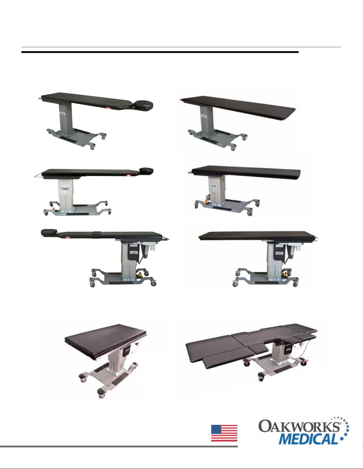
Imaging Tables
CFPM300
integrated headrest top
CFPM400
integrated headrest top
CFPM301
integrated headrest top
CFPM401
integrated headrest top
CFPMFXH
integrated headrest top
CFPM100
integrated headrest top
CFPM300
rectangular top
CFPM400
rectangular top
CFPM301
rectangular top
CFPMB301
rectangular top - Bariatric Version
CFPM401
rectangular top
CFPMFXH
rectangular top
CFPM100
rectangular top
CFUR301
Urology Table
CFUR401
Urology Table
www.oakworksmed.com · 717.235.6807
CFLU401
Lithotripsy Table
made in the USA
with US & imported parts

© Copyright 2007
OAKWORKS® , Inc.
This manual was originally drafted
and approved in the English language.
Printed in USA
All rights are reserved. No
part of this document may be
photocopied, reproduced or
translated to another language
without prior written consent
of OAKWORKS®, Inc.
OAKWORKS® is a registered
trademark of OAKWORKS®, Inc.
Notice
The information contained in this
document is subject to change
without notice and should not
be construed as a commitment by
OAKWORKS®, Inc.
OAKWORKS®, Inc. assumes no
responsibility for any errors that
may appear in this document nor
does it make expressed or implied
warranty of any kind with regard
to this material, including, but not
limited to, the implied warranties
of merchantability and fitness for
a particular purpose.
OAKWORKS®, Inc. shall not be
liable for incidental or consequential damages in connection with or
arising out of the furnishing, performance, or use of this document
and the program material which it
describes.

TABLE OF CONTENTS
Product Use Description ...............................................................................................................1
Important Safety Instructions
Symbol Identification ..................................................................................................................1
Contradictions ..............................................................................................................................1
Safety Instructions .................................................................................................................. 2-3
Product Description & Photo
CFPMFXH ............................................................................................................................................ 4
CFPM100 .............................................................................................................................................. 5
CFPM300 .............................................................................................................................................. 6
CFPM400 .............................................................................................................................................. 7
CFPM301 .............................................................................................................................................. 8
CFPMB301 - Bariatric .......................................................................................................................... 9
CFPM401 ............................................................................................................................................ 10
CFLU401 - Lithotripsy ...................................................................................................................... 11
CFUR301 - Urology ........................................................................................................................... 12
CFUR401 - Urology ........................................................................................................................... 13
Installation
Grounding ................................................................................................................................. 14
Directions for Use
Hand Control / Foot Control Operations ..........................................................................15-16
Bubble Levels .............................................................................................................................17
Angle Indicator ..........................................................................................................................17
Patient Restraint Strap ..............................................................................................................17
Remove / Replace the Table Top Pad ....................................................................................18
Adjusting Cranial Positioning Pads (integrated headrest tops only) ...................................18
Locking Casters Use ..................................................................................................................19
Emergency Stop ........................................................................................................................19
Weight Capacity & Patient Use ................................................................................................20
Urology Table Bag Hoop ..........................................................................................................20
Lithotripsy/Urology & Urology Table End Extensions .........................................................21
Lithotripsy/Urology & Urology Table Lateral Extensions ....................................................21
Lithotripsy Table used as Urology Table ................................................................................22
Urology Table Lateral Extensions ............................................................................................22
Carbon Fiber Arm Board ..........................................................................................................23
Adjustable T-Rail Clamp...........................................................................................................23
Spine Positioning System II ......................................................................................................24
Fluoro Extender .........................................................................................................................24
Reference - Usable Imaging Area Diagrams
CFPMFXH & CFPM 100 - Integrated Headrest & Rectangular Tops ..............................25-26
CFPM400, CFPM300, CFPM401 & CFPM301 - Integrated Headrest Top .............................27
CFPM400, CFPM300, CFPM401, CFPM301 & CFPMB301 - Rectangular Top ......................28
CFUR301 & CFUR401 - Urology Top ......................................................................................29
CFLU401 - Lithotripsy / Urology Top ....................................................................................30
Cleaning & Disinfection ...............................................................................................................31
Inspections & Maintenance .......................................................................................................31
Warranty Information ....................................................................................................................31
Model Number & Serial Number ..............................................................................................32
Specifications
Product Specifications ...............................................................................................................33
Environmental Conditions ........................................................................................................33
Electrical Specifications .............................................................................................................33
Guidance and manufacturer’s declaration -
Electromagnetic emissions ........................................................................................................34
Recommended separation distances ........................................................................................34
Guidance and manufacturer’s declaration -
Electromagnetic immunity ..................................................................................................35-36
Contact Information ............................................................................................back cover
PRODUCT USE DESCRIPTION / IMPORTANT SAFETY INSTRUCTIONS
PRODUCT USE DESCRIPTION
Oakworks® Imaging Tables are radiographic tables intended for use with mobile or compact stationary C-arm
Imaging Systems. It is ideally suited for pain management imaging and therapeutic procedures. These tables are
suitable to use for diagnostic x-ray imaging and imaging during therapeutic procedures such as spinal injections,
vertebroplasty procedures and other pain management procedures. The CFLU & CFUR Tables are designed for
Lithotripsy and Urology procedures. It is intended to be operated by a healthcare professional in a medical environment. No special training is required but a review of the following Safety Instructions is important for the safety of the operator and patient. The healthcare professional should read and understand this entire manual before
use with a patient.
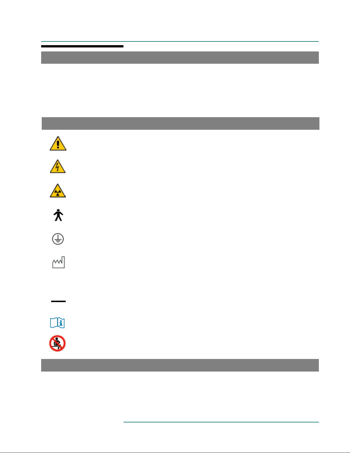
SYMBOL IDENTIFICATION
This symbol, when used in this manual and on product labels, represents a caution warning. Be sure to
read and comply with all precautions and warnings.
This symbol, when used in this manual and on product labels, warns against an electrical shock hazard. Be
sure to observe and comply with all warnings.
This symbol, when used in this manual and on product labels, indicates the potential of exposure to harmful
x-rays. Be sure to read and comply with all warnings.
This symbol, when used in this manual and on product labels, indicates that the table and components
are a Type B Applied Part pursuant to IEC 60601-1: 2005.
This symbol, when used in this manual or on product labels, indicates a Protective Earth (Ground)
Terminal.
This symbol, when used in this manual or on product labels, indicates the date of manufacture of the
device.
This symbol, when used in this manual or on product labels, indicates alternating current (AC).
~
----
CONTRADICTIONS
This symbol, when used in this manual or on product labels, indicates direct current (DC).
This symbol is used to indicate that the operator should consult the user manual.
Sitting is prohibited in this area.
The Oakw ork s® Imaging Tables should not be used with Imaging systems having intensifier screens or film cassettes larger than 12 inches (30 cm) when an oblique angle of view is being used. The tables are not designed for
and should not be used with Magnetic Resonance Imaging procedures.
1

IMPORTANT SAFETY INSTRUCTIONS
IMPORTANT SAFETY INSTRUCTIONS
CAUTION
After unpacking your table, inspect it thoroughly for damage. If you suspect a problem do not use the table and
call our customer service department at 800-916-4612.
Improper use of this device can cause injury. Be sure to read all operating instructions prior to use.
Weight limit (patient and accessories): 227 kg / 500 lbs. distributed evenly. (Bariatric Table only: 340 kg / 750 lbs.)
Do not sit beyond warning line on carbon fiber top. On Lithotripsy / Urology Top - Do not sit on any extensions
(Weight Limit: 200 lbs. / 91 kg.)
The table utilizes four locking casters to permit movement of the table within the imaging suite. Accidental movement of the table may occur. Lock casters prior to accomplishing imaging of the patient. Lock casters when the
patient is mounting & dismounting the table.
The table should not be used adjacent to or stacked with other equipment and that if adjacent or stacked use is necessary,
the table should be observed to verify normal operation in the configuration in which it will be used.
The use of Accessories, transducers, and cables other than those specified (with the exception of transducers and cables
sold by the Manufacturer of this device as replacement parts for internal components) may result in increased Emissions
or decreased Immunity of the table.
The table is designed to be a standalone table used with radiographic equipment. This table must not be modified or
incorporated into any other equipment.
There may be pinch points under the table top. Do not have any body part under the top when the table is in
motion.
Be certain that the table is completely lowered prior to discharging an ambulatory patient. The patient may lose balance
and fall. NOTE: The CFPMFXH is a fixed height table. It is recommended that all patients are assisted onto the table
(physical assistance & step stools with side rails is recommended.)
READ AND SAVE THESE INSTRUCTIONS
Patient must be secured with Safety Restraint Strap prior to using the tables.
Medical Electrical Equipment needs special precautions regarding EMC and needs to be installed and put into
service according to the EMC information provided in the specifications at the end of this manual. (Excluding
CFPMFXH)
Portable and Mobile RF Communications Equipment can affect Medical Electrical Equipment. (Excluding
CFPMFXH)
This table is not suitable for use in the presence of flammable anesthetic mixture with air or oxygen or nitrous oxide.
Electrical Shock Hazard. (Excluding CFPMFXH) The power supply/control module is located inside the lifting
column and under the top. No user serviceable parts are inside. Refer servicing to qualified personnel. Unplug wall
connector prior to contact with any cables connected to the power supply.
To avoid the risk of electric shock, this equipment must only be connected an outlet this is properly grounded. See
GROUNDING instructions in this manual.
Grounding reliability can only be achieved when this equipment is connected to an equivalent 3 prong receptacle
marked “Hospital Only” or “Hospital Grade”.
Oakworks medical tables are designed and built to provide many years of dependable service. Please follow local
regulations and laws when disposing of the electrical components used in this table.
2

IMPORTANT SAFETY INSTRUCTIONS
WARNING
To reduce the risk of burns, fire, electric shock or injury to persons:
1. Unplug this furnishing from the electrical outlet before cleaning.
2. Unplug from outlet before adding or removing parts.
3. Never operate this furnishing if it has a damaged cord or plug, if it is not working properly, if it has been dropped or
damaged, or dropped into water. Contact Oakworks Customer Service before use.
4. Keep the cord away from heated surfaces.
5. Never drop or insert any object into any opening.
6. Do not use outdoors.
7. Do not operate where aerosol (spray) products are being used or where oxygen is being administered.
DANGER
The potential of exposure to harmful x-rays exists when this table is in use. The use of adequate x-ray barrier
devices is necessary to provide protection to both the operator and the patient. X-ray barrier devices are recommended
for the patient outside of the intended target area to prevent exposure to scattered radiation from the x-ray generating source.
The tabletop has a typical aluminum filtration equivalence of 1.10 mm as measured at 100 kVp and a half value (HVL)
of 3.6 mm. (NOTE: Bariatric Top has a typical aluminum filtration equivalence of 1.50 mm. as measured at 100 kVp
and a half value (HVL) of 3.6 mm.)
• Oak wor ks® Imaging Tables may be used for x-ray imaging where the x-ray generator is located below the
tabletop and the image receptor is located above the tabletop. This is the recommended method. The tables may
also be used for x-ray imaging where the x-ray generator is located above the tabletop and the image receptor is
located below the tabletop. This application will result in greater patient exposure to x-rays. The operator must
weigh this issue with the imaging requirements and patient exposure issues.
• The Imaging Tables may be used with the x-ray generator above the tabletop and a film cassette located on
the tabletop. (See contradictions regarding film cassette size.)
• The x-ray generator should never be located above the tabletop when the Oakw ork s® Imaging Table and
the Oakw ork s® Spine Positioning System/Prone Pillow are used together. This type of use requires that the x-ray
generator is located below the tabletop and the imaging intensifier or film cassette located above the tabletop.
3
PRODUCT DESCRIPTION
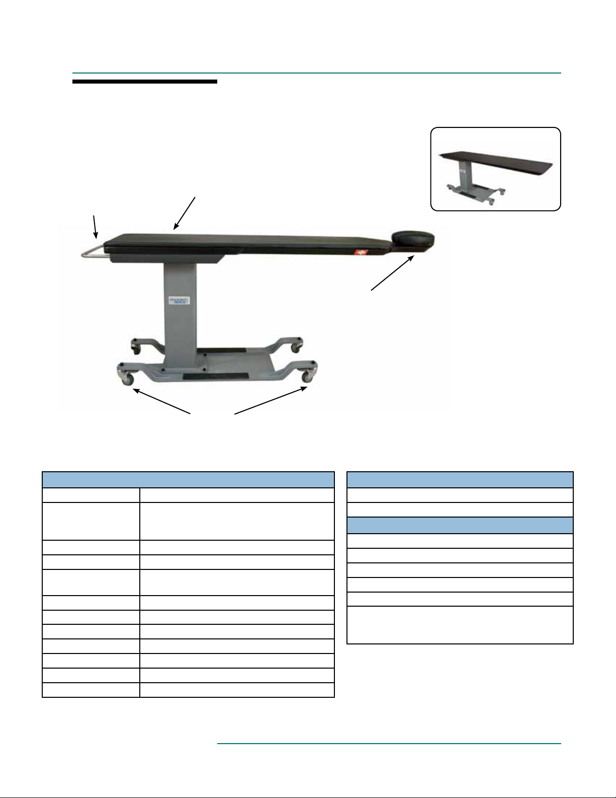
CFPMFXH
Hand Rail
24” X 80” RECTANGULAR TOP
Carbon Fiber Integrated Headrest
Top with Removable Table Top Pad
Integrated
Face Rest
with Crescent
Face Pad
Locking
Casters
STANDARD SPECIFICATIONS
Fixed Height 37” (91cm)
Choice of Tabletop:
- Integrated Headrest
- Rectangular
Table Voltage Options 120V/60Hz or 230V/50Hz
Table Capacity 500 lbs. (227 kg.) distributed evenly
4” (10cm) Locking
Casters
Padding 1” (3cm) Comfort Foam
Crescent Face Pad Integrated Headrest Only
Patient Restraint Strap Must be used during all procedures
Upholstery Terra Touch
Table Weight 368 lbs. (167 kg.)
Warranty 4 year parts, 1 year labor
Safety Listings FDA, cETLus, CE marked
22” (56cm) W x 84” (214cm) L
24” (61cm) W x 80” (203cm) L
Locking / Unlocking Casters for mobile or
permanent positioning
™
™
OPTIONS
5” (13cm) Locking Casters
Custom heights: 31”-37” (79-91cm)
ACCESSORIES
Carbon Fiber Arm Board (Standard or Wide)
Spine Positioning System II
Adjustable T-rail Clamp
2” (5cm) Tabletop Pad
Fluoro Extender
Headrest 2-Pad Set:
1) 2” (5 cm) High x 12” (30.5 cm) Square Pad
2) 4” (10 cm) High x 12” (30.5 cm) Square Pad
For electrical specs, see Specifications section.
4
PRODUCT DESCRIPTION
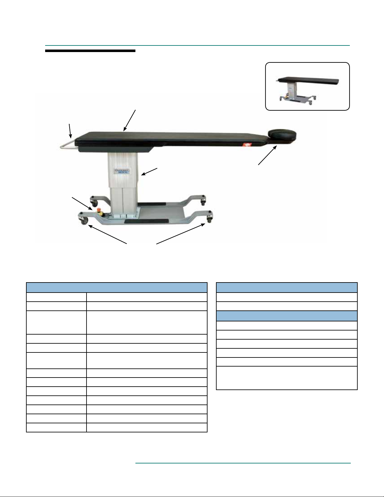
CFPM100
Hand Rail
Emergency
Stop
Carbon Fiber Integrated Headrest
Top with Removable Table Top Pad
Electronic
Lift Tower
Locking
Casters
24” X 80” RECTANGULAR TOP
Integrated
Face Rest
with Crescent
Face Pad
STANDARD SPECIFICATIONS
Height Motion Powered 22”-40” (56-102cm)
Foot Control height motion
Choice of Tabletop:
- Integrated Headrest
- Rectangular
Table Voltage Options 120V/60Hz or 230V/50Hz
Table Capacity 500 lbs. (227 kg) distributed evenly
4” (10 cm.) Locking
Casters
Padding 1” (3cm) Comfort Foam
Crescent Face Pad Integrated Headrest Only
Patient Restraint Strap Must be used during all procedures
Upholstery Terra Touch
Table Weight 343 lbs. (146 kg)
Warranty 4 year parts, 1 year labor
Safety Listings FDA, cETLus, CE marked
22” (56cm) W x 84” (214cm) L
24” (61cm) W x 80” (203cm) L
Locking / Unlocking Casters for mobile or
permanent positioning
™
™
OPTIONS
5” (13cm) Locking Casters
International Electric Congurations
ACCESSORIES
Carbon Fiber Arm Board (Standard or Wide)
Spine Positioning System II
Adjustable T-rail Clamp
2” (5cm) Tabletop Pad
Fluoro Extender
Headrest 2-Pad Set:
1) 2” (5 cm) High x 12” (30.5 cm) Square Pad
2) 4” (10 cm) High x 12” (30.5 cm) Square Pad
For electrical specs, see Specifications section.
5
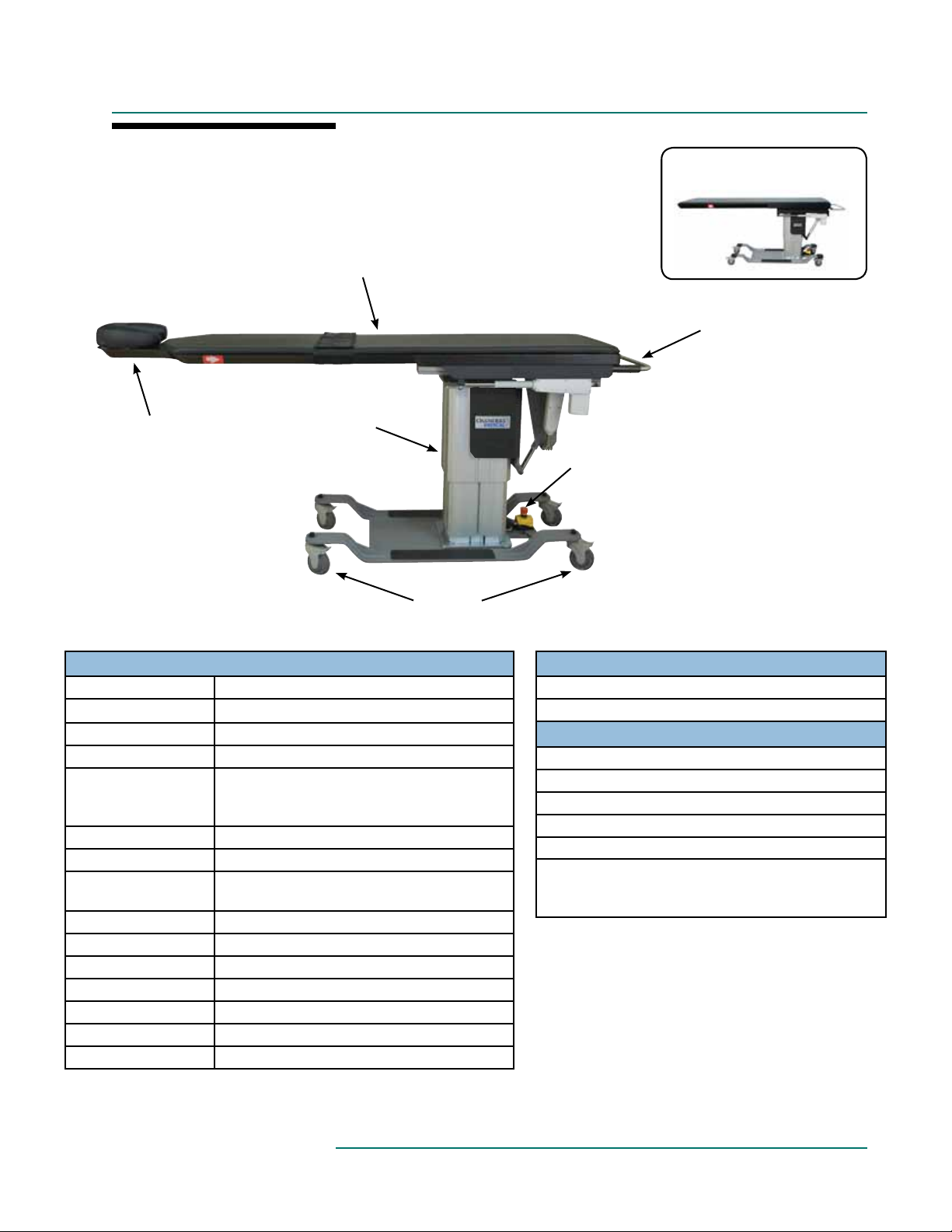
PRODUCT DESCRIPTION
CFPM300
Carbon Fiber Integrated Headrest
Top with Removable Table Top Pad
Electronic
Integrated
Face Rest
with Crescent
Face Pad
Lift Tower
24” X 80” RECTANGULAR TOP
Hand Rail
Emergency
Stop
Locking
Casters
STANDARD SPECIFICATIONS
Motion 1 Powered 26”-44” (66-112cm) Height Range
Motion 2 Powered +15°/-12° Trendelenburg
Motion 3 Powered ±15 Lateral Tilt
Hand & Foot Control All powered motions
Choice of Tabletop:
- Integrated Headrest
- Rectangular
Table Voltage Options 120V/60Hz or 230V/50Hz
Table Capacity 500 lbs. (227 kg) distributed evenly
4” (10 cm.) Locking
Casters
Padding 1” (3cm) Comfort Foam
Crescent Face Pad Integrated Headrest Only
Patient Restraint Strap Must be used during all procedures
Upholstery Terra Touch
Table Weight 498 lbs. (226kg)
Warranty 4 year parts, 1 year labor
Safety Listings FDA, cETLus, CE marked
22” (56cm) W x 84” (214cm) L
24” (61cm) W x 80” (203cm) L
Locking / Unlocking Casters for mobile or
permanent positioning
™
™
OPTIONS
5” (13cm) Locking Casters
International Electric Congurations
ACCESSORIES
Carbon Fiber Arm Board (Standard or Wide)
Spine Positioning System II
Adjustable T-rail Clamp
2” (5cm.) Tabletop Pad
Fluoro Extender
Headrest 2-Pad Set:
1) 2” (5 cm) High x 12” (30.5 cm) Square Pad
2) 4” (10 cm) High x 12” (30.5 cm) Square Pad
For electrical specs, see Specifications section.
6
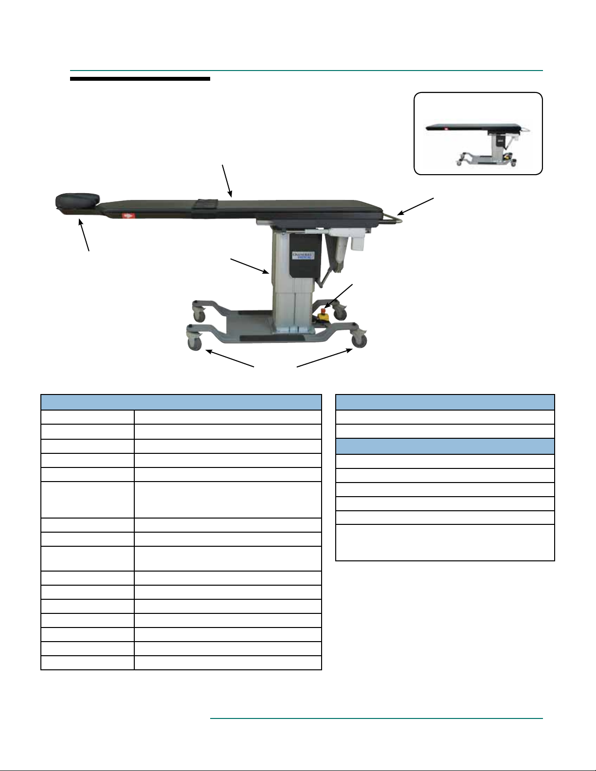
PRODUCT DESCRIPTION
CFPM400
Carbon Fiber Integrated Headrest
Top with Removable Table Top Pad
Electronic
Integrated
Face Rest
with Crescent
Face Pad
Lift Tower
24” X 80” RECTANGULAR TOP
Hand Rail
Emergency
Stop
Locking
Casters
STANDARD SPECIFICATIONS
Motion 1 Powered 26”-44” (66-112cm) Height Range
Motion 2 Powered +15°/-12° Trendelenburg Tilt
Motion 3 Powered ±15° Lateral Tilt
Motion 4 Powered 10” (25cm) Longitudinal Travel
Hand & Foot Control All powered motions
Choice of Tabletop:
- Integrated Headrest
- Rectangular
Table Voltage Options 120V/60Hz or 230V/50Hz
Table Capacity 500 lbs. (227 kg) distributed evenly
4” (10 cm.) Locking
Casters
Padding 1” (3cm) Comfort Foam
Crescent Face Pad Integrated Headrest Only
Patient Restraint Strap Must be used during all procedures
Upholstery Terra Touch
Table Weight 498 lbs. (226 kg)
Warranty 4 year parts, 1 year labor
Safety Listings FDA, cETLus, CE marked
22” (56cm) W x 84” (214cm) L
24” (61cm) W x 80” (203cm) L
Locking / Unlocking Casters for mobile or
permanent positioning
™
™
OPTIONS
5” (13cm) Locking Casters
International Electric Congurations
ACCESSORIES
Carbon Fiber Arm Board (Standard or Wide)
Spine Positioning System II
Adjustable T-rail Clamp
2” (5cm) Tabletop Pad
Fluoro Extender
Headrest 2-Pad Set:
1) 2” (5 cm) High x 12” (30.5 cm) Square Pad
2) 4” (10 cm) High x 12” (30.5 cm) Square Pad
For electrical specs, see Specifications section.
7
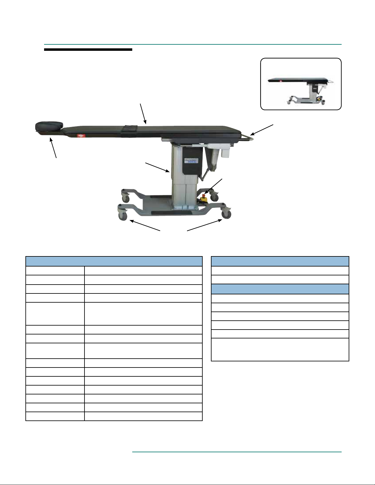
PRODUCT DESCRIPTION
CFPM301
Carbon Fiber Integrated Headrest
Top with Removable Table Top Pad
Electronic
Integrated
Face Rest
with Crescent
Face Pad
Lift Tower
24” X 80” RECTANGULAR TOP
Hand Rail
Emergency
Stop
Locking
Casters
STANDARD SPECIFICATIONS
Motion 1 Powered 25”-43” (64-109cm) Height Range
Motion 2 Powered +15°/-11° Trendelenburg
Motion 3 Powered 10” (25cm) Longitudinal Travel
Hand & Foot Control All powered motions
Choice of Tabletop:
- Integrated Headrest
- Rectangular
Table Voltage Options 120V/60Hz or 230V/50Hz
Table Capacity 500 lbs. (227 kg) distributed evenly
4” (10 cm.) Locking
Casters
Padding 1” (3cm) Comfort Foam
Crescent Face Pad Integrated Headrest Only
Patient Restraint Strap Must be used during all procedures
Upholstery Terra Touch
Table Weight 538 lbs. (244 kg)
Warranty 4 year parts, 1 year labor
Safety Listings FDA, cETLus, CE marked
22” (56cm) W x 84” (214cm) L
24” (61cm) W x 80” (203cm) L
Locking / Unlocking Casters for mobile or
permanent positioning
™
™
OPTIONS
5” (13cm) Locking Casters
International Electric Congurations
ACCESSORIES
Carbon Fiber Arm Board (Standard or Wide)
Spine Positioning System II
Adjustable T-rail Clamp
2” (5cm) Tabletop Pad
Fluoro Extender
Headrest 2-Pad Set:
1) 2” (5 cm) High x 12” (30.5 cm) Square Pad
2) 4” (10 cm) High x 12” (30.5 cm) Square Pad
For electrical specs, see Specifications section.
8
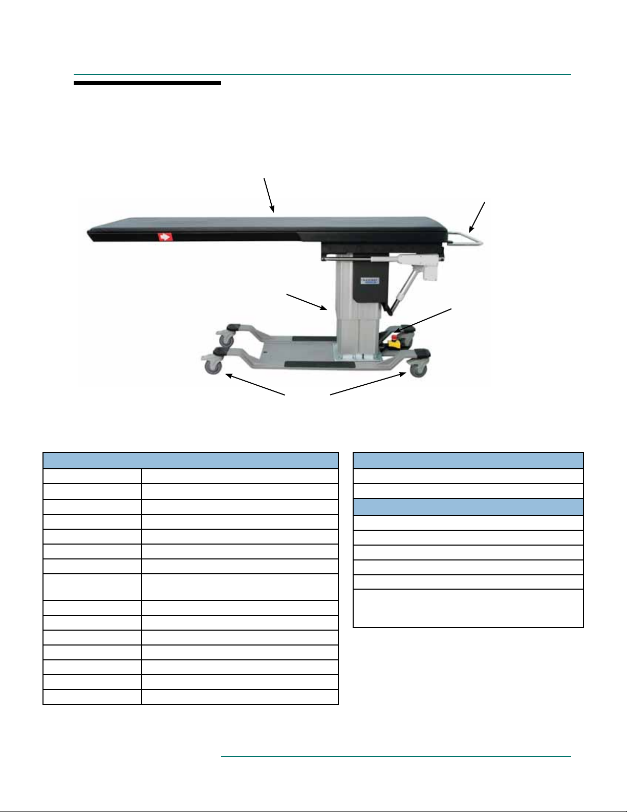
PRODUCT DESCRIPTION
CFPMB301 - Bariatric
24” x 80” Bariatric Carbon Fiber
Top with Removable Table Top Pad
Hand Rail
Electronic
Lift Tower
Emergency
Stop
Locking
Casters
STANDARD SPECIFICATIONS
Motion 1 Powered 26”-44” (66-112 cm) Height Range
Motion 2 Powered +15°/-11° Trendelenburg
Motion 3 Powered 10” (25cm) Longitudinal Travel
Hand & Foot Control All powered motions
Rectangular Top 24” (61cm) W x 80” (203cm) L
Table Voltage Options 120V/60Hz or 230V/50Hz
Table Capacity 750 lbs. (340 kg) distributed evenly
4” (10 cm.) Locking
Casters
Padding 1” (3cm) Comfort Foam
Crescent Face Pad Integrated Headrest Only
Patient Restraint Strap Must be used during all procedures
Upholstery Terra Touch
Table Weight 573 lbs. (260 kg)
Warranty 4 year parts, 1 year labor
Safety Listings FDA, cETLus, CE marked
Locking / Unlocking Casters for mobile or
permanent positioning
™
™
OPTIONS
5” (13cm) Locking Casters
International Electric Congurations
ACCESSORIES
Carbon Fiber Arm Board (Standard or Wide)
Spine Positioning System II
Adjustable T-rail Clamp
2” (5cm) Tabletop Pad
Fluoro Extender
Headrest 2-Pad Set:
1) 2” (5 cm) High x 12” (30.5 cm) Square Pad
2) 4” (10 cm) High x 12” (30.5 cm) Square Pad
For electrical specs, see Specifications section.
9

PRODUCT DESCRIPTION
CFPM401
Carbon Fiber Integrated Headrest
Top with Removable Table Top Pad
Electronic
Integrated
Face Rest
with Crescent
Face Pad
Lift Tower
24” X 80” RECTANGULAR TOP
Hand Rail
Emergency
Stop
Locking
Casters
STANDARD SPECIFICATIONS
Motion 1 Powered 26”-44” (66-112cm) Height Range
Motion 2 Powered +15°/-12° Trendelenburg Tilt
Motion 3 Powered 10” (25cm) Longitudinal Travel
Motion 4 Powered ±4” (10cm) Lateral Travel
Hand & Foot Control All powered motions
Choice of Tabletop:
- Integrated Headrest
- Rectangular
Table Voltage Options 120V/60Hz or 230V/50Hz
Table Capacity 500 lbs. (227 kg) distributed evenly
4” (10 cm.) Locking
Casters
Padding 1” (3cm) Comfort Foam
Crescent Face Pad Integrated Headrest Only
Patient Restraint Strap Must be used during all procedures
Upholstery Terra Touch
Table Weight 548 lbs. (249 kg)
Warranty 4 year parts, 1 year labor
Safety Listings FDA, cETLus, CE marked
22” (56cm) W x 84” (214cm) L
24” (61cm) W x 80” (203cm) L
Locking / Unlocking Casters for mobile or
permanent positioning
™
™
OPTIONS
5” (13cm) Locking Casters
International Electric Congurations
ACCESSORIES
Carbon Fiber Arm Board (Standard or Wide)
Spine Positioning System II
Adjustable T-rail Clamp
2” (5cm) Tabletop Pad
Fluoro Extender
Headrest 2-Pad Set:
1) 2” (5 cm) High x 12” (30.5 cm) Square Pad
2) 4” (10 cm) High x 12” (30.5 cm) Square Pad
For electrical specs, see Specifications section.
10

PRODUCT DESCRIPTION
CFLU401 - Lithotripsy/Urology Top
Short Extension
Hand Rail
(under end)
Emergency
Stop
End Extension
T-rail
(along each side)
Carbon Fiber Top with
Removable Table Top Pad
Lateral Extensions (4)
Locking
Casters
STANDARD SPECIFICATIONS
Motion 1 Powered 27”-45” (66-112cm) Height Range Urology Bag Hoop Clips onto T-rails (bag not included)
Motion 2 Powered +15°/-12° Trendelenburg Tilt Intregrated T-rails .38” (1cm) Thick x 1.13” (3cm) High US Stan-
dard
Motion 3 Powered 10” (25cm) Longitudinal Travel Patient Restraint Strap Must be used during all procedures
Motion 4 Powered ±4” (10 cm.) Lateral Travel 5” (12.5 cm.) Locking
Hand & Foot Control All powered motions
23” (58cm) W x 47” (119cm) L (Radiolucent
Main Top Dimensions
dimensions: 19” (48cm) W x 23.7” (60cm))
Casters
Table Extensions (1) 23” (58cm) W x 28” (71cm) L - End
Table Voltage Options 120V/60Hz or 230V/50Hz (2) 8” (20cm) W x 11” (28cm) L - Lateral
Table Capacity
Padding 1” (3cm) Comfort Foam
500 lbs. (227 kg) distributed evenly (1) 8” (20cm) W x 14” (36cm) L - Lateral
200 lbs. (91 kg) (on all extensions) (1) 8” (20cm) W x 24” (61cm) L - Lateral
™ Upholstery Terra Touch™
Table Weight 618 lbs. (280 kg) Safety Listings FDA, cETLus, CE marked
Warranty 4 year parts, 1 year labor
Locking / Unlocking Casters for mobile or
permanent positioning
(1) 23” (58cm) W x 16” (41cm) L
OR
23” (58cm) W x 20” (51cm) L - Short
OPTIONS
4” (10cm) Locking Casters
International Electric Congurations
ACCESSORIES
Carbon Fiber Arm Board (Standard or Wide)
Spine Positioning System II
Adjustable T-rail Clamp
2” (5cm) Tabletop Pad
Fluoro Extender
Litho/Urology Drape
For electrical specs, see Specifications section.
11

PRODUCT DESCRIPTION
CFUR301 - Urology Top
T-rail
STANDARD SPECIFICATIONS
Motion 1 Powered 26”-44” (66-112cm) Height Range
Motion 2 Powered +15°/-11° Trendelenburg Tilt
Motion 3 Powered 10” (25cm) Longitudinal Travel
Hand & Foot Control All powered motions
Main Top Dimensions
Table Extensions
Intregrated T-rails
Urology Bag Hoop Clips onto T-rails (bag not included)
Table Capacity
4” (10 cm.) Locking
Casters
Padding 1” (2.5 cm.) Comfort Foam
Patient Restraint Strap Must be used during all procedures
Upholstery Terra Touch
Table Weight 568 lbs. (258 kg)
Warranty 4 year parts, 1 year labor
Safety Listings FDA, cETLus, CE marked
23” (58cm) W x 47” (119cm) L (Radiolucent
dimensions: 19” (48cm) W x 23.7” (60cm))
(1) 23” (58.4 cm.) W x 28” (71.1 cm.) L - End
(2) 5” (12.5 cm.) W x 24” (61 cm.) L - Lateral
.38” (1cm) Thick x 1.13” (3cm) High US Standard
500 lbs. (227 kg) distributed evenly
200 lbs. (91 kg) (on all extensions)
Locking / Unlocking Casters for mobile or
permanent positioning
™
Electronic
Lift Tower
Locking
Casters
™
Urology Carbon Fiber Top with
Removable Table Top Pad
Hand Rail
(at end)
Emergency
Stop
OPTIONS
5” (13cm) Locking Casters
International Electric Congurations
ACCESSORIES
Carbon Fiber Arm Board (Standard or Wide)
Spine Positioning System II
Adjustable T-rail Clamp
2” (5cm) Tabletop Pad
Fluoro Extender
For electrical specs, see Specifications section.
12

PRODUCT DESCRIPTION
CFUR401 - Urology Top
T-rail
STANDARD SPECIFICATIONS
Motion 1 Powered 27”-45” (69-114cm) Height Range
Motion 2 Powered +15°/-11° Trendelenburg Tilt
Motion 3 Powered 10” (25cm) Longitudinal Travel
Motion 4 Powered ±4” (10cm) Lateral Travel
Hand & Foot Control All powered motions
Main Top Dimensions
Table Extensions
Intregrated T-rails
Urology Bag Hoop Clips onto T-rails (bag not included)
Table Capacity
4” (10 cm.) Locking
Casters
Padding 1” (3cm) Comfort Foam
Patient Restraint Strap Must be used during all procedures
Upholstery Terra Touch
Table Weight 590 lbs. (268 kg)
Warranty 4 year parts, 1 year labor
Safety Listings FDA, cETLus, CE marked
23” (58cm) W x 47” (119cm) L (Radiolucent
dimensions: 19” (48cm) W x 23.7” (60cm))
(1) 23” (58cm) W x 28” (71cm) L - End
(2) 5” (13cm) W x 24” (61cm) L - Lateral
.38” (1cm) Thick x 1.13” (3cm) High US Standard
500 lbs. (227 kg) distributed evenly
200 lbs. (91 kg) (on all extensions)
Locking / Unlocking Casters for mobile or
permanent positioning
™
Electronic
Lift Tower
Locking
Casters
™
Urology Carbon Fiber Top with
Removable Table Top Pad
Hand Rail
(at end)
Emergency
Stop
OPTIONS
5” (13cm) Locking Casters
International Electric Congurations
ACCESSORIES
Carbon Fiber Arm Board (Standard or Wide)
Spine Positioning System II
Adjustable T-rail Clamp
2” (5cm) Tabletop Pad
Fluoro Extender
For electrical specs, see Specifications section.
13

INSTALLATION
The Imaging tables come completely assembled and ready to use. Plug the cord into a functioning outlet
that is rated for the table. (see Grounding below)
Arrange the power cord and control cords so that they will not create a tripping hazard and where
the controls are located to your liking and are conveniently accessible.
Be sure access to plug is not blocked for disconnecting the table from power.
GROUNDING
DANGER
This product must be grounded. If it should malfunction or break down, grounding
provides a path of least resistance for electrical current to reduce the risk of electric
shock. This product is equipped with a cord having an equipment-grounding conductor
and a grounding pin. The pin must be plugged into an appropriate outlet that is properly installed and grounded in accordance with all local codes and ordinances. See U.S.
sample below.
Improper connection of the equipment-grounding conductor can result in a risk of electric shock. Check with a qualified electrician or service person if you are in doubt as to
whether the product is properly grounded. Do not modify the plug provided with the
product - if it will not fit the outlet; have a proper outlet installed by a qualified electrician.
Risk of Electric Shock - Connect this furnishing to a properly grounded outlet only.
Grounding Methods
Correct Implementation Incorrect Implementation
14

DIRECTIONS FOR USE
FOOT CONTROL - ONE MOTION
Used to raise and lower the height of the table.
FOOT CONTROL - THREE MOTION
Used to control table Vertical Height, Trendelenburg, Lateral Tilt OR Vertical Height, Trendelenburg,
Longitudinal Motion. Control functions dependent upon table’s features.
FOOT CONTROL - FOUR MOTION
Used to control table Vertical Height, Trendelenburg, Longitudinal Motion, Lateral Tilt OR Vertical Height,
Trendelenburg, Longitudinal Motion, Lateral Motion. Control functions dependent upon table’s features.
15

DIRECTIONS FOR USE
HAND CONTROL - THREE MOTION
Used to control table Vertical Height, Trendelenburg, Lateral Tilt OR Vertical Height, Trendelenburg,
Longitudinal Motion. Control functions dependent upon table’s features.
HAND CONTROL - FOUR MOTION
Used to control table Vertical Height, Trendelenburg, Longitudinal Motion, Lateral Tilt OR Vertical Height,
Trendelenburg, Longitudinal Motion, Lateral Motion.Control functions dependent upon table’s features.
16

DIRECTIONS FOR USE
BUBBLE LEVELS
Bubble levels are installed on the handle end of the table to aid the operator to determine the horizontal plane.
ANGLE INDICATOR
Standard on CFLU401, CFUR401 and
CFUR301 Tables. Optional on all other
Imaging Tables.
To use angle indicator, simply press “on/off”
button on the left side of the indicator.
NOTE: Do not press “zero” unless table is
in the horizontal position.
PATIENT RESTRAINT STRAP
CAUTION
The strap has Velcro® attached to the ends. The Strap is attached as follows:
1. Place the center of the strap around the patient’s waist.
Relocate the strap as necessary for adequate clearance.
2. Take the ends of the strap down around the tabletop.
Pull the strap snug underneath the table and press the two
Velcro® ends together.
3. Check the strap to assure adequate patient restraint prior
to using the Trendelenburg functions.
The Patient Restraint Strap must be used during all procedures to prevent the patient from
falling off the table.
17

DIRECTIONS FOR USE
REMOVE / REPLACE THE TABLE TOP PAD
CAUTION
Make sure the top is not in motion when removing / replacing the table top pad.
Remove Table Pad by pulling flaps at the ends & sides
of the table until the hook and loop fastener becomes
unanchored.
Replace pad by first centering on the table and then
pressing flaps in place, anchoring with the hook and
loop fasteners.
ADJUSTING THE CRANIAL POSITIONING PADS
(INTEGRATED HEADREST TOPS ONLY)
Prone Positioning:
The Crescent Face Pad is held in place by hook &
loop fasteners.
Place close in to the edge of the table with sides
together for smaller patients or further away from
the edge with sides apart for larger patients.
Underside of Tabletop
Supine Positioning: (Accessory)
Pads attach to the integrated face rest extension with hook & loop fasteners that hold the pad securely in place.
Pads are provided that give two levels of elevation: 2” or 4” (5 or 10cm)
2” or 4”
(5 or 10cm)
18

DIRECTIONS FOR USE
LOCKING CASTERS USE
All four casters should be locked at all times during use with a patient.
LOCKING THE CASTERS
1. Place your shoe on the end of the casters locking tab.
2. Press firmly downward until you here a clicking noise
and the caster is locked.
UN-LOCKING THE CASTERS
1. Place your shoe on top of the casters locking tab.
2. Press firmly inward and downward until you here a
clicking noise and the caster is unlocked.
EMERGENCY STOP
All electric tables are equipped with an emergency stop switch.
To stop the
operation, push
the red button.
To reset, rotate
the red button
clockwise.
If necessary, you can also remove the plug from the outlet. Se sure access is not blocked for disconnecting
the table from power.
19

DIRECTIONS FOR USE
WEIGHT CAPACITY & PATIENT USE
The oakwo rks® table top is rated at 500 lb. (227 kg) load evenly distributed. (Bariatric table is rated
CAUTION
ing or dismounting the table. Table should be flat when mounting and dismounting. Patient should mount and dismount near the
lifting column. Table top should be moved fully to the rear after each use.
DO NOT sit beyond this point.
at 750 lbs. (340 kg)) To minimize any risk to the patient, do not allow the patient to sit on the face
rest area beyond the warning line on the table top. Casters should be locked when patient is mount-
safe zone
UROLOGY TABLE BAG HOOP
1. Slide bag over Urology hoop.
2. Attach ends of hoop to the ends of the table T-rails.
Tighten hoop ends to the T-rail.
Completed assembly.
20

DIRECTIONS FOR USE
LATERAL EXTENSIONS - LITHOTRIPSY/UROLOGY & UROLOGY TOPS
CAUTION
Do not sit on any extensions. Weight Limit: 200 lbs. / 91 kg.
There are four lateral extensions for the Lithotripsy table. (2 - 8” x 11”, 1 - 8” x 14” and 1 - 8” x 24”).
8” x 11”
(20 x 28cm)
8” x 24”
(20 x 61cm)
8” x 14”
(20 x 36cm)
8” x 11”
(20 x 28cm)
The 2 - 8” x 11” (20 x
28 cm) are angled and
designed to be used
on both sides of the
Lithotripsy opening.
The 1 - 8” x 24” (20
x 61cm) extension is
designed to bridge
the Lithotripsy opening.
The 8” x 14” (20 x
36cm) extension can
be used as required
for your procedure
along with other
extensions.
The Lateral
Extensions are
clamped to the T-rail
with a locking clamp
design.
21

DIRECTIONS FOR USE
END EXTENSIONS - LITHOTRIPSY/UROLOGY & UROLOGY TOPS
CAUTION
There are extensions which can be inserted on either end of the table. (1) - 23” x 28” (58 x 71cm) and (1) - 23” x
16” (58 x 41cm) - Lithotripsy/Urology, (1) - 23” x 28” (58 x 71cm) - Urology
TO INSERT EXTENSION
Slide the two “arms” into the ends of the table
top. Push fully in and extension arms will
drop slightly into a locking pin.
Do not sit on any extensions. Weight Limit: 200 lbs. / 91 kg.
TO REMOVE EXTENSION
Lift extension slightly and pull away from
table top.
LITHOTRIPSY TABLE USED AS A UROLOGY TABLE
If the extensions are removed from the Lithotripsy Table, the table can be used as a Urology Table. A bag hoop is
included with your table. (Refer to Urology Table Bag Hoop directions for use).
UROLOGY TABLE LATERAL EXTENSIONS
CAUTION
There are 2 lateral extensions for the Urology Table - (2) 5” x 24” (13 x 61cm). These extensions can be used as
required to extend the effective width of the table top.
Do not sit on any extensions. Weight Limit: 200 lbs. / 91 kg.
22

DIRECTIONS FOR USE
CARBON FIBER ARM BOARD (ACCESSORY)
Do not place undue weight or downward pressure on the Carbon Fiber Arm Board. It is a posi-
CAUTION
Use
This radiolucent device can be used with any flat support surface where ionizing radiation (x-ray) is utilized for imaging. It can be used to support arms and feet.
Directions
Unfold the Arm Board and slide the Base Section under the patient and the table pad. Position the patient and the
Support Section to suit the needs of the procedure. The weight of the patient will hold the Arm Board in place.
Rotate the Support Section to the desired position. This section rotates up to 180º.
tioning device for the arms and should not be used as leverage to get on or off the table. Injury
can occur. DO NOT exceed 30 lbs. (14 kg.) of load on the Support Section. Injury can occur.
Prone Position at 135º
To remove the Arm Board, ask the patient to move their limb off the Support Section and lift their body slightly. This
will allow you to pull out the base section of the Arm Board.
Fold the Base and Support sections for storage.
Supine Position at 180º
Support Section
Base Section
ADJUSTABLE T-RAIL CLAMP USE (ACCESSORY)*
1. Open T-rail clamp.
2. Slide T-rail to desired location.
3. Tighten T-rail clamp.
Note: The Integrated T-Rails are US standard
size of .38” (1cm) thick by 1.13” (3cm) wide.
*Not for use on CFPMB301 - Bariatric table
23

DIRECTIONS FOR USE
SPINE POSITIONING SYSTEM II (ACCESSORY)
For directions on the use of the Spine Positioning System, see publication “Spine Positioning System”
Part number MMMMNUP0003
CONTOURED TORSO
SUPPORT PAD
CRESCENT FACE
REST PAD
RADIOLUCENT
FRAME WITH
ADJUSTABLE
FACE REST
CONTOURED
TORSO WEDGE
8” X 22” X 2”
(20 x 56 x 5cm)
LARGE
RECTANGULAR
ADJUSTER PAD
FLUORO EXTENDER (ACCESSORY)
CAUTION
The Oakworks® Fluoro Extender is radiolucent and offers extra width only where you need it for
greater positioning accuracy with optimum imaging. The Fluoro Extender is inserted under the table
top pad.
7” X 12” X 1½”
(18 x 31 x 4cm)
SMALL
RECTANGULAR
ADJUSTER PAD
8” (20cm)
SEMIROUND
BOLSTER
CARRY CASE
Do not place undue weight or downward pressure on the Fluoro Extender. It is a positioning
device for the arms and should not be used as leverage to get on or off the table. Injury can
occur.
24

REFERENCE
USABLE IMAGING AREA - CFPMFXH & CFPM100
INTEGRATED HEADREST TOPS ONLY
CENTERED FOR A-P VIEW:
NO IMAGE NO IMAGE NO IMAGE
OBLIQUE 30° VIEW FOR VERTICAL:
CAUDAL 30° VIEW FOR VERTICAL:
25

REFERENCE
USABLE IMAGING AREA - CFPMFXH & CFPM100
RECTANGULAR TOPS ONLY
CENTERED FOR A-P VIEW:
NO IMAGE NO IMAGE NO IMAGE
OBLIQUE 30° VIEW FOR VERTICAL:
CAUDAL 30° VIEW FOR VERTICAL:
26

REFERENCE
USABLE IMAGING AREA - CFPM400, CFPM300, CFPM401 & CFPM301
INTEGRATED HEADREST TOPS ONLY
CENTERED FOR A-P VIEW:
NO IMAGE NO IMAGE NO IMAGE
OBLIQUE 30° VIEW FOR VERTICAL:
CAUDAL 30° VIEW FOR VERTICAL:
27

REFERENCE
USABLE IMAGING AREA - CFPM400, CFPM300, CFPM401 & CFPM301
RECTANGULAR TOPS ONLY
CENTERED FOR A-P VIEW:
NO IMAGE NO IMAGE NO IMAGE
OBLIQUE 30° VIEW FOR VERTICAL:
CAUDAL 30° VIEW FOR VERTICAL:
28

REFERENCE
OBLIQUE 30° VIEW FROM VERTICAL:
CAUDAL 30° VIEW FROM VERTICAL:
USABLE IMAGING AREA - CFUR301 & CFUR 401
CENTERED FOP A-P VIEW:
CENTERED FOR A-P VIEW:
47.0"
[119.38cm]
23.3"
23.0"
[58.42cm]
[59.06cm]
No Image
NO IMAGE NO IMAGE NO IMAGE
[5.08cm] TYP
2.0"
19.0"
[48.26cm]
21.0"
[53.34cm]
OBLIQUE 30° VIEW FOR VERTICAL:
47.0"
[119.38cm]
23.3"
[59.06cm]
[6.99cm] TYP
No Image
[39.37cm]
CAUDAL 30° VIEW FOR VERTICAL:
41.5"
[105.41cm]
20.0"
[50.80cm]
2.0"
[5.08cm] TYP
2.8"
15.5"
No Image
23.0"
[58.42cm]
19.0"
[48.26cm]
29

REFERENCE
OBLIQUE 30° VIEW FROM VERTICAL:
CAUDAL 30° VIEW FROM VERTICAL:
USABLE IMAGING AREA - CFLU401
CENTERED FOP A-P VIEW:
CENTERED FOR A-P VIEW:
47.0"
[119.38cm]
23.3"
[59.06cm]
No Image
NO IMAGE NO IMAGE NO IMAGE
23.0"
[58.42cm]
2.0"
[5.08cm] TYP
19.0"
[48.26cm]
OBLIQUE 30° VIEW FOR VERTICAL:
21.0"
[53.34cm]
CAUDAL 30° VIEW FOR VERTICAL:
23.3"
[59.06cm]
No Image
20.0"
[50.80cm]
47.0"
[119.38cm]
2.8"
[6.99cm] TYP
15.5"
[39.37cm]
41.5"
[105.41cm]
2.0"
[5.08cm] TYP
No Image
23.0"
[58.42cm]
19.0"
[48.26cm]
30

CLEANING & DISINFECTION / INSPECTIONS / WARRANTY
CLEANING & DISINFECTION
WARNING
Use a 10% sodium hypochlorite (bleach) solution or Recommended Disinfectants on all surfaces. Clean all sides
of each upholstered section. Follow the directions on the disinfectant and wipe off excess.
Recommended Disinfectants
Protex, MadaCide, Accell TB, Virox®
Before cleaning with any liquid cleaner be sure to unplug the power cord from the outlet.
Note: Damage caused by unapproved substances will not be covered under the warranty.
DO NOT use citrus based cleaners or other strong cleaners, such as alcohol, acetone, higher concentrations of
bleach or other products that contain high concentrations of these substances.
DO NOT expose the fabric to temperatures below 50°F/10°C or above 104°F/40°C.
DO NOT expose the fabric to direct sunlight, adhesives, liquids, or abrasive materials.
INSPECTIONS & MAINTENANCE
RECOMMENDED REGULAR INSPECTIONS (monthly or local standard)
• Check for damage to the power, hand control or foot control cables.
• Visually inspect components for obvious damage that could cause problems during operation.
RECOMMENDED PERIODIC INSPECTIONS (yearly or local standard)
• Check for damage to the power, hands control or foot control cables and all visible wiring.
• Visually inspect components for obvious damage that could cause problems during operation.
• Check all mechanical functions using the hand control. Repeat using the foot control. Check for abnormal
noises.
• Replace any missing or illegible labels.
• Check that all fasteners are present and fastened securely.
• Check table grounding.
• Clean unusual buildup of dirt on the chair and/or parts of the chair not normally cleaned on a regular
basis.
• Check for tears or cracks in the upholstery.
MAINTENANCE
• No specific maintenance tasks are required.
• Oakworks medical tables/chairs are designed and built to provide many years of dependable service.
Please follow local regulations and laws when disposing of the electrical components used in this chair.
•
For all Customer Service related problems refer to the Service Manual
WARRANTY
View complete warranty details at www.oakworks.com
31

MODEL NUMBER & SERIAL NUMBER
MODEL & SERIAL NUMBERS
The model number and serial number are located on the lift column.
MODEL NUMBER DESCRIPTION
FL 40 IF 22 26 84 MG TT XX XX
Model Number
Imaging Table
Power Rating
US 120 V 60 Hz 8.2 A
Class 1 Equipment
Duty Cycle: MAX 2 minutes ON
18 minutes OFF
3034177
CONFORMS TO:
ANSI/AAMI STD
ES60601-1
IEC STD 60601-1-6
Certied to CAN/CSA
STD C22.2 No. 60601-1
Part No. 70537-1 rev. A
European Authorized
Representative:
Emergo Europe
Molenstraat 15
The Hague, 2513 BH
Netherlands
Phone: 717-235-6807 FAX: 717-235-6798 www.oakworks.com
16796025 FL40IF222684MGTTZZF8 Ser#: FL4563563
CFPM400 IF 22 x 26-44 x 84 MG/TT/F8
TTCoal 01/04/2013 Order#:654321
Notes: Sample Product Label
This product complies with DHHS radiation performance
standards 21 CFR Subchapter J, in the effect at the time
of manufacturer.
923 East Wellspring Rd., New Freedom, PA 17349
Model Numbers and Serial Numbers always start with a letter.
Options: May be in any order
EU = Europe
AU = Australia
GB = United Kingdom
5C = 5” Casters
Serial Number
Spaces not used
Fabric: TerraTouch
TM
Padding: Comfort Foam
Table Top Length
Minimum Table Height
Table Top Width
To p
IF = Integrated Face Rest
RT = Rectangular
BA = Bariatric
UR = Urology
LI = Lithotripsy
Base Motion:
10 = Vertical
30 = Vertical, Trendelenburg & Roll
31 = Vertical, Trendelenburg & Longitudinal
40 = Vertical, Trendelenburg, Longitudinal & Roll
41 = Vertical, Trendelenburg, Lateral & Longitudinal
BA = Bariatric Vertical, Trendelenburg & Longitudinal
FD = Fixed Height
Fluoroscopy Table
32

SPECIFICATIONS
PRODUCT SPECIFICATIONS
NORTH AMERICA EUROPE
Weight 359-452 lbs. 163-205 kg.
Shipping Weight 452-544 lbs. 205-247 kg.
Lifting Capacity 500 lbs. (750 lbs. Bariatric) 227 kg. (340 kg. Bariatric)
Materials of Construction This product contains no latex.
ALUMINUM EQUIVALENCE THICKNESS
100 kVp, HVL of 3.6mm = 1.10 (1.35 max) 1.65” (4.2 cm)
100 kVp, HVL of 3.6mm = 1.50 (1.79 max) 2.18” (5.5 cm)
100 kVp, HVL of 3.6mm = 1.66 (2.00 max) .5” (1.3 cm)
100 kVp, HVL of 3.6mm = .88 (1.07 max) 1” (2.5 cm)
100 kVp, HVL of 3.6mm = .88 (1.07 max) 2” (5 cm)
Aluminum Filtration
Equivalence and thickness of Carbon Fiber
Tabletop
Non-Bariatric Tops
Bariatric Tops
All Extensions
1” (2.5 cm.) Table Pad
2” (5 cm.) Table Pad
This product complies with United States Department of Health and Human Services radiation performance
standards, 21 CFR Sub chapter J, in effect at the time of manufacture for radiographic tables.
ENVIRONMENTAL CONDITIONS
Conditions Temperature Humidity Atmospheric Pressure
Normal Use 50° (10°C) to 104° (40°C) 20% to 60% RH 98 to 105 kPa
Storage & Transport -20° (-29°C) to 135° (57°C) 20% to 95% RH 98 to 105 kPa
ELECTRICAL SPECIFICATIONS
CFPM400, CFPM401, CFPM301,
CFLU401, CFUR401 & CFUR301
CFPM100 Tables Only
Designed for:
Input Service (All electric
tables)
Current Draw 5.8 amps 3.0 amps 8.2 amps 4.5 amps
Maximum Momentary
Current Consumption
Voltage Output to Actuators
Electric Shock Protection Class 1 Equipment
Tabletop Applied Part
Ingress Protection Rating
Mode of Operation
NORTH AMERICA
120 VAC/15
amp/60 Hz
9.0 amps 4.5 amps 12.3 amps 6.7 amps
120 VDC 220 VDC
Intermittent Operation: MAX 2 minutes ON / 18 minutes off
EUROPE
230 VAC/10
amp/50/60 Hz
Type B Applied Part
NORTH AMERICA
120 VAC/15
amp/60 Hz
24V top,
120V Column
IPX0
Tables
EUROPE
220 VAC/10
amp/50/60 Hz
24V top,
220V Column
33

SPECIFICATIONS
Guidance and Manufacturer’s Declaration - Electromagnetic Emissions
All Equipment and Systems (except CFPMFXH)
The table is intended for use in the electromagnetic environment specied below. The customer or the
user of the table should assure that it is used in such an environment.
Emissions Test Compliance Electromagnetic environment - guidance
The table uses RF energy only for its internal
RF emissions
CISPR 11
RF emissions
CISPR 11
Harmonic emissions
IEC 61000-3-2
Flicker emissions
IEC 61000-3-3
Group 1
Class B
Class A
Complies
function. Therefore, its RF emissions are very low
and are not likely to cause any interference in
nearby electronic equipment.
The table is suitable for use in all establishments
other than domestic and those directly con-
nected to the public low-voltage power supply
network that supplies buildings used for domestic
purposes.
Recommended Separation Distances between the portable and mobile RF
Communications equipment and the Oakworks Imaging Tables
for Equipment and Systems that are NOT life-supporting
The table is intended for use in the electromagnetic environment in which radiated RF disturbances
are controlled. the customer or the user of the table can help prevent electromagnetic interference
by maintaining a minimum distance between portable and mobile RF communications equipment
(transmitters) and the table as recommended below, according to the maximum output of the
communications equipment.
Rated maximum output
power of transmitter
W
0.01 0.12 0.12 0.23
0.1 0.38 0.38 0.73
1 1.2 1.2 2.3
10 3.8 3.8 7.3
100 12 12 23
For transmitters rated at a maximum output power not listed above, the recommended separation
distance d in meters (m) can be estimated using the equation applicable to the frequency of the
transmitter, where P is maximum output power rating of the transmitter in watts (W) according to the
transmitter manufacturer.
NOTE 1 At 80 MHz and 800 MHz, the separation distance for the higher frequency range applies.
NOTE 2 These guidelines may not apply in all situations. Electromagnetic propagation is affected by
absorption and reection from structures, objects and people.
Separation distance according to frequency of transmitter (m)
150 kHz to 80 MHz
d = 1.2 √ P
80 MHz to 800 MHz
d = 1.2 √ P
800 MHz to 2.5 GHz
d = 2.3 √ P
34

SPECIFICATIONS
Guidance and Manufacturer’s Declaration - Immunity All Equipment and Systems
The table is intended for use in the electromagnetic environment specied below. The customer or the
user of the table should assure that it is used in such an environment.
Immunity Test IEC 60601 test level Compliance level
Electrostatic discharge
(ESD)
EN/IEC 61000-4-2
Electrical fast transient/
burst
EN/IEC 61000-4-4
Surge
EN/IEC 61000-4-5
Voltage Dips/Dropout
EN/IEC 61000-4-11
Power frequency (50/60
Hz)
Magnetic Field
EN/IEC 61000-4-8
NOTE U
T is the a.c. mains voltage prior to application of the test level.
±6 kV contact
±8 kV air
±2 kV for power supply lines
±1 kV for input/output lines
±1 kV line(s) to line(s)
±2 kV line(s) to earth
<5 % U
T
(>95 % dip in UT)
for 0,5 cycle
40 % U
T
(60 % dip in UT)
for 5 cycles
70 % U
T
(30 % dip in UT)
for 25 cycles
<5 % U
T
(>95 % dip in UT)
for 5 sec
±6 kV contact
±8 kV air
±2 kV for power supply lines
Not applicable for input/
output lines
±1 kV line(s) to line(s)
±2 kV line(s) to earth
<5 % U
(>95 % dip in UT)
for 0,5 cycle
40 % U
(60 % dip in UT)
for 5 cycles
70 % U
(30 % dip in UT)
for 25 cycles
<5 % U
(>95 % dip in UT)
for 5 sec
3 A / m 3 A / m
T
T
T
T
Electromagnetic
environment - guidance
Floors should be wood,
concrete or ceramic tile.
If oors are covered with
synthetic material, the relative humidity should be at
least 30 %.
Mains power quality should
be that of a typical commercial or hospital environment.
Mains power quality should
be that of a typical commercial or hospital environment.
Mains power quality should
be that of a typical commercial or hospital environment.
If the user of the table requires continued operation
during power mains interruptions, it is recommended
that the table be powered
from an uninterruptible
power supply or a battery.
Power frequency magnetic
elds should be at levels
characteristic of a typical
location in a typical commercial or hospital environment.
35

SPECIFICATIONS
Guidance and Manufacturer’s Declaration - Immunity
Equipment and Systems that are NOT life-supporting
The table is intended for use in the electromagnetic environment specied below. The customer or the
user of the table should assure that it is used in such an environment.
Immunity Test IEC 60601 test level Compliance level
Conducted RF
IEC 61000-4-6
Radiated RF
IEC 61000-4-3
3 Vrms
150 kHz to 80 MHz
3 V/m
80 MHz to 2,5 GHz
3 Vrms
3 V/m
Electromagnetic
environment - guidance
Portable and mobile RF communications equipment
should be used no closer to any part of the table, including cables, than the recommended separation
distance calculated from the equation applicable
to the frequency of the transmitter.
Recommended separation distance
d = 1.2 √ P
d = 1.2 √ P 80 MHz to 800 MHz
d = 2.3 √ P 800 MHz to 2,5 GHz
Where P is the maximum output power rating of the
transmitter in watts (W) according to the transmitter
manufacturer and d is the recommended separation distance in meters (m).
Field strengths from xed RF transmitters, as deter-
mined by an electromagnetic site survey, a should
be less than the compliance level in each frequency
range.
Interference may occur in the vicinity of equipment
marked with the following symbol:
b
NOTE 1 At 80 MHz and 800 MHz, the higher frequency range applies.
NOTE 2 These guidelines may not apply in all situations. Electromagnetic propagation is affected by absorption and
reection from structures, objects and people.
a Field strengths from xed transmitters, such as base stations for radio (cellular/cordless) telephones and land mobile
radios, amateur radio, AM and FM radio broadcast and TV broadcast cannot be predicted theoretically with accura-
cy. To assess the electromagnetic environment due to xed RF transmitters, an electromagnetic site survey should be
considered. If the measured eld strength in the location in which the table is used exceeds the applicable RF com-
pliance level above, the table should be observed to verify normal operation. If abnormal performance is observed,
additional measures may be necessary, such as re-orienting or relocating the table
b Over the frequency range 150 kHz to 80 MHz, eld strengths should be less than 3 V/m.
36

USER MANUAL
OAKWORKS®
Imaging Tables
CONTACT INFORMATION:
Oak works® Inc.
923 East Wellspring Road
New Freedom, PA 17349
Phone: 717-235-6807
FAX: 717-235-6798
www.oakworksmed.com
3034177
CONFORMS TO:
ANSI/AAMI STD ES60601-1
IEC STD 60601-1 3RD EDITION
IEC STD 60601-1-2 3RD EDITION
IEC STD 60601-1-6 3RD EDITION
IEC STD 60601-2-32
CERTIFIED TO CAN/CSA STD C22.2 NO. 60601-1
CB TEST CERTIFICATE AND REPORT
Manual Part Number MMMNST0008-EN
Revision level: C
English, Printed in USA
made in the USA
with US & imported parts
 Loading...