

Page 1
s
10. Warranty
OAKTON warrants this instrument to be free from significant deviations in material
and workmanship for a period of one year from date of purchase. If repair or
adjustment is necessary and has not been the result of abuse or misuse within
the warrantied time period, please return—freight prepaid—and correction will
be made without charge. OAKTON alone will determine if the product problem
is due to deviations or customer misuse.
Out-of-warranty products will be repaired on a charge basis.
11. Return of items
Authorization must be obtained from our Customer Service Department before
returning items for any reason. When applying for authorization, please include
data regarding the reason the items are to be returned. For your protection, items
must be carefully packed to prevent damage in shipment and insured against possible damage or loss. We will not be responsible for damage resulting from careless or
insufficient packing. Arestocking charge will be made on all unauthorized returns.
NOTE: We reserve the right to make improvements in design, construction, and
appearance of products without notice.
OPERATING INSTRUCTIONS
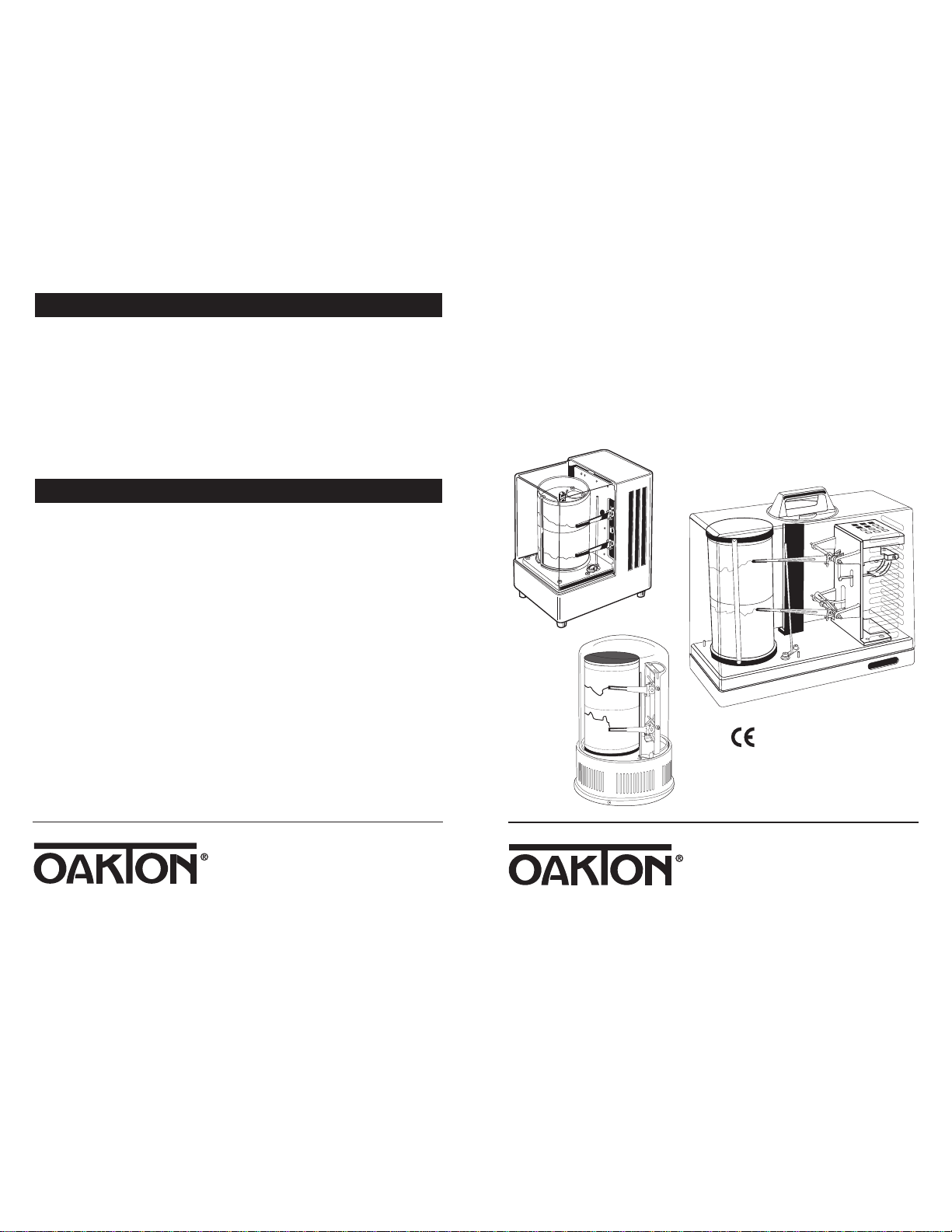
OAKTON®Models 08369-50, -70
37250-00, -10, -20
Hygrothermograph
00703-07
Find Quality Products Online at: [email protected]
www.GlobalTestSupply.com
Printed in the U.S.A. 1/00
Page 2

NOTES
Table of Contents
Write down the name and information of your OAKTON distributor here.
1. Introduction.........................................................................................4-5
2. Components............................................................................................6
3. Getting started .......................................................................................7
3.1 Unpacking .............................................................................................................................7
3.2 Attaching the cylinder drum ..............................................................................................7
4. Hygrothermograph operation...........................................................8-21
4.1 Powering your hygrothermograph ................................................................................8-9
4.2 Cartridge pens ....................................................................................................................10
4.3 Setting the time...................................................................................................................11
4.4 Chart paper....................................................................................................................12-17
4.5 Calibration adjustment.................................................................................................18-19
4.6 Changing drum rotation length..................................................................................20-21
5. Installing optional axial fan.................................................................22
6. Precautions ...........................................................................................23
7. Specifications ...................................................................................24-25
8. Ordering information...........................................................................26
9. Appendix 1: Readings in areas with high humidity ............................27
10. Warranty.............................................................................................28
11. Return of Items...................................................................................28
32
Find Quality Products Online at: [email protected]
www.GlobalTestSupply.com
Page 3
1. Introduction
Thank you for selecting an OAKTON thermohygrometer. These precision instruments are useful for monitoring temperature and relative humidity conditions over
time. They create a permanent chart recording of these measurements for your
records. Their quartz-controlled drive maintains an even drum speed even when
batteries are weak (or when the spring winding runs down).
Typical applications include general weather measurements, agriculture,
horticulture, monitoring the condition of test laboratories, humidity chambers,
computer rooms, precision machinery rooms, food storage facilities, warehouses,
museums, bank vaults, film and book storage facilities.
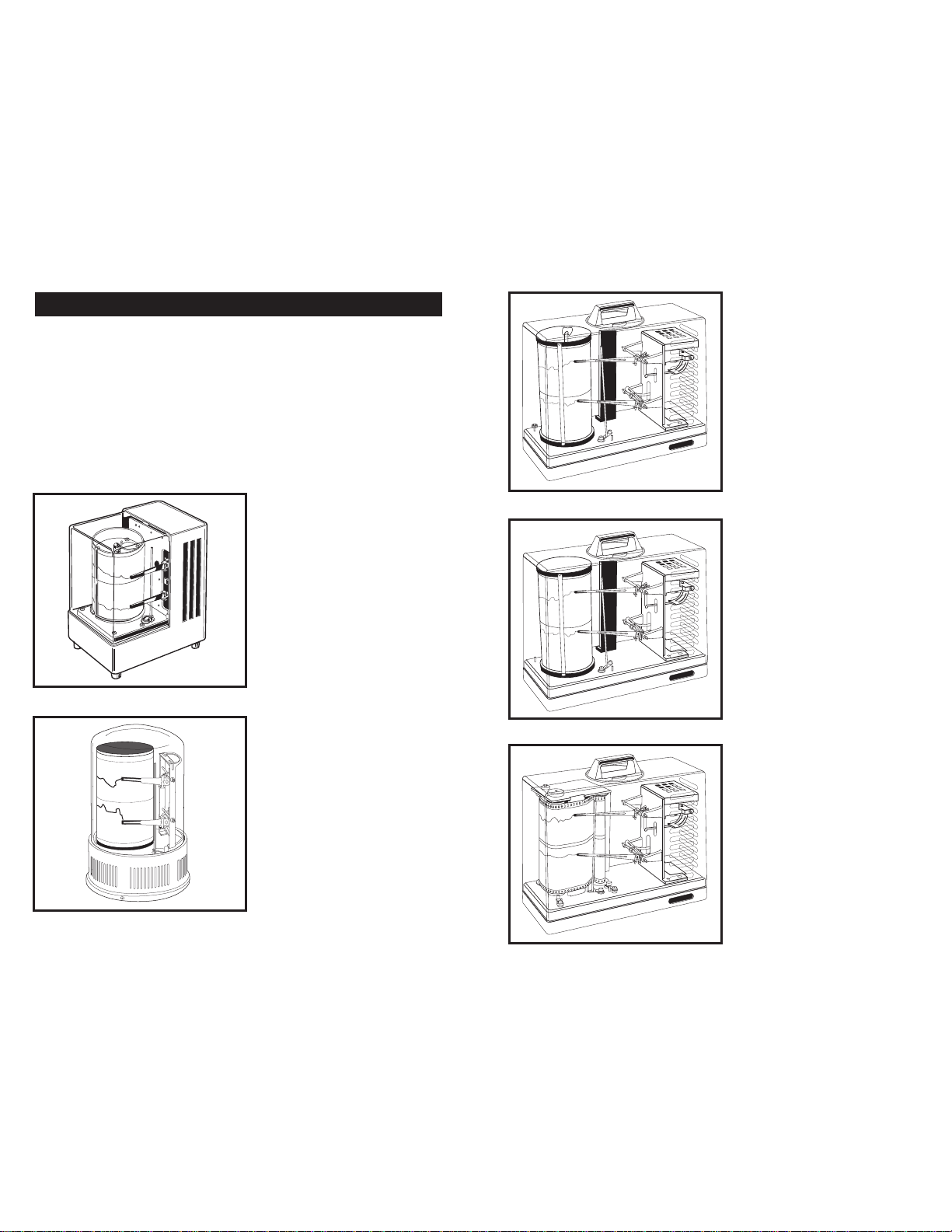
You have one of five available models:
Minidrum hygrothermograph
Model number: 08369-70
Special features:
• Compact size
• Records on 7-day rotation
• Protective acrylic cover locks
into place
Domed minidrum
hygrothermograph
Model number: 08369-50
Special features:
• Our most compact model
• Records on 7-day rotation
• Protective glass dome
Spring-wound, two-speed
hygrothermograph
Model number: 37250-10
Special features:
• Spring wound—
no batteries needed!
• Records on 1- or 7-day rotation
• Protective acrylic cover locks
into place
Three-speed hygrothermograph
Model number: 37250-00
Special features:
• Records on 1- or 7-, or 32-day
rotation
• Protective acrylic cover locks
into place
Long-cycle hygrothermograph
Model number: 37250-20
Special features:
• Records on 1 or 3 month rotation
• Protective acrylic cover locks
into place
54
Find Quality Products Online at: [email protected]
www.GlobalTestSupply.com
Page 4
2. Components
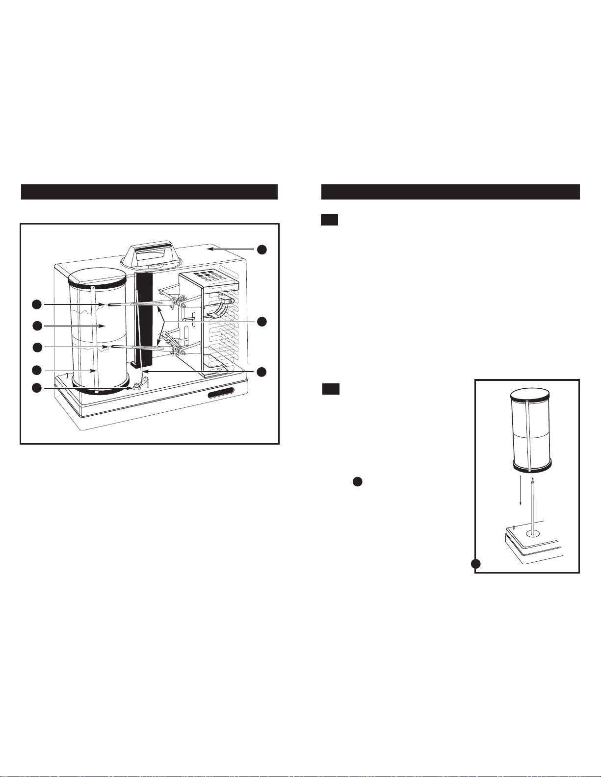
All OAKTON hygrothermographs have these same features:
1
2
3
3. Getting started
3.1
Unpacking
1. Remove all components from the packing material.
6
7
2. Carefully remove the acrylic or glass protective cover from the hygrothermo-
graph. If your model has a handle, turn the carrying handle to the left until it
stops, then lift up the protective cover.
3. Carefully remove the styrofoam piece located beneath the pen arm mechanism.
4. Remove the white paper that secures the humidity pen.
5. Lift the metal pen holding fitting up from the temperature pen until it is removed
from the pen guide.
6. Move the pen lift lever towards you to pull the temperature and humidity pens to
their resting position.
NOTE: Keep all original packing in case you need to transport the instrument.
4
5
1. Pen tip for temperature
2. Cylinder drum with quartz clock
3. Pen tip for humidity
4. Paper holder
5. Pen lift lever
6. Protective cover
7. Pen arms
8. Pen guide
8
3.2
Attaching the cylinder drum
NOTE: Long-cycle model 37250-20 already
has an attached cylinder drum.
1. Unscrew the hold-down nut from the
center shaft.
2. Carefully insert the cylinder drum onto
the center shaft. Make sure the cylinder
drum is completely lowered over the
center shaft.
See figure
3. Replace the hold-down nut on the top of
A
the center shaft.
A
76
Find Quality Products Online at: [email protected]
www.GlobalTestSupply.com
Page 5
4. Hygrothermograph operation
4.1
Powering your hygrothermograph
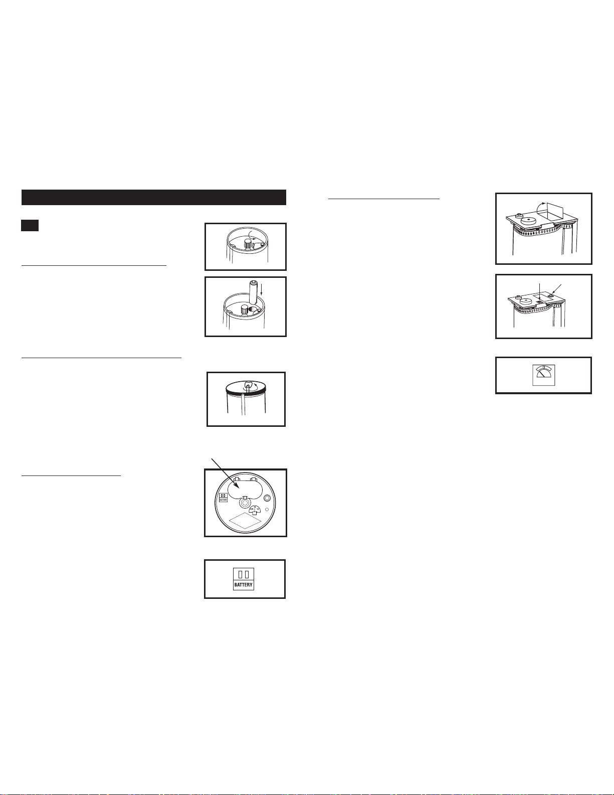
Minidrum models (08369-50 and -70):
These models require one AAbattery. The battery
compartment is located on top of the cylinder
drum. To open the battery compartment, slide the
cover of the battery compartment to the side. Make
sure that the + end of the battery is facing up.
Spring wound, 2 speed model (37250-10):
This model is spring wound (requires no batteries).
The spring winding shaft is located on top of the
cylinder drum. To wind up the unit, turn the shaft
counterclockwise until it is too stiff to move
any further. This hygrothermograph will make a
“clicking” sound while running. The drum will
maintain an even rotation speed even when the
spring is winding down.
Long cycle model (37250-20):
This model requires one C battery. The battery
compartment is located on top of the cylinder
drum. To open the battery compartment, flip
open the lid on top of the cylinder drum. Note
polarity inside the battery compartment.
This model features a battery indicator. To check
the battery, press the red check button next to the
battery compartment. The power indicator has
green, white and red zones.
• the green zone means the battery is in
good condition.
• The white zone means the battery is low
and will have to be replaced soon.
• The red zone means the battery is very
low and should be replaced immediately.
Close-up of battery indicator
BATTERY
3 speed model (37250-00):
This model requires two C batteries. The battery
compartment is located on top of the cylinder
drum. To open the battery compartment, pull the
silver knob on top of the battery compartment
away from the center of the cylinder drum. Note
polarity on the lid of the battery compartment.
This model features a battery indicator. To check
the battery, press the red check button next to the
battery compartment. Note the color of the LED
indicator:
• A green LED means the batteries are in
good condition.
• A red LED means the batteries need to
be replaced.
Top of Drum
Close-up of battery indicator
98
Find Quality Products Online at: [email protected]
www.GlobalTestSupply.com
Page 6
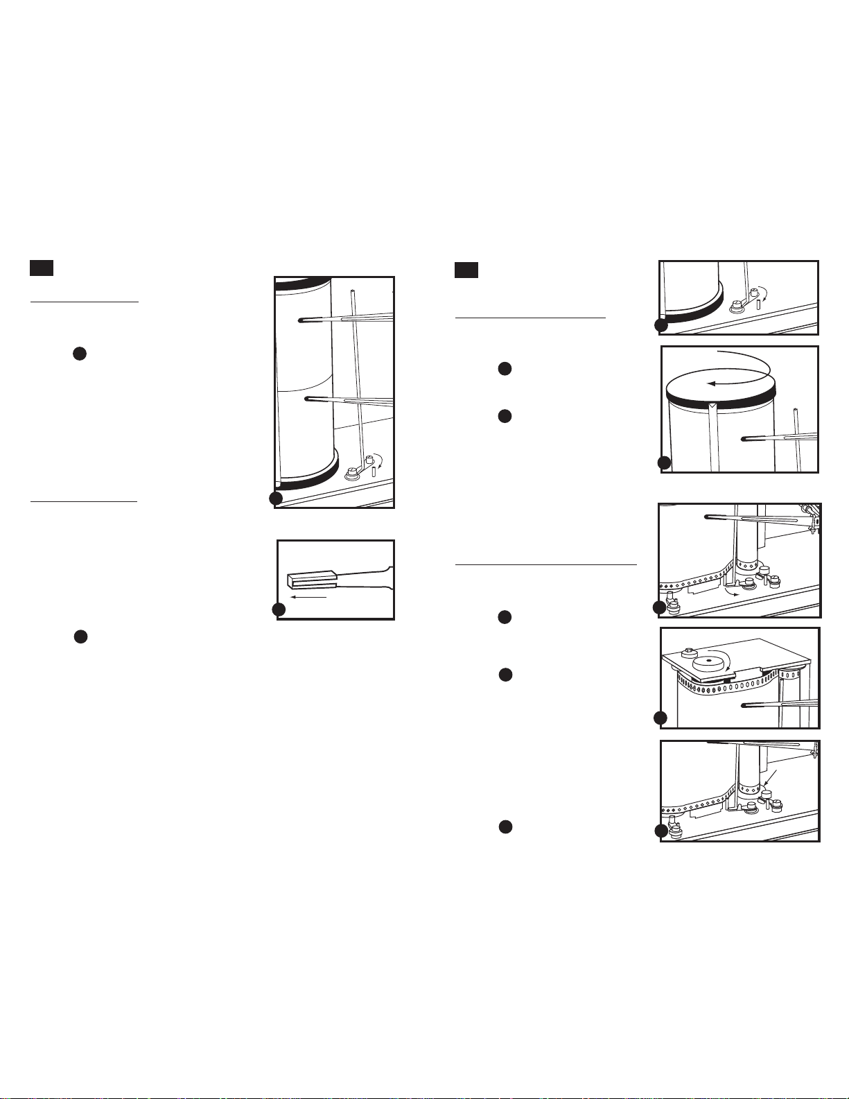
4.2
Cartridge pens
To operate the pens:
1. Pull the pen lift lever towards you to move the
temperature and humidity pens to their resting
position.
See figure
A
2. Remove the pen caps by rotating them counter
clockwise.
3. Push the pen lift lever away from you until the
temperature and humidity pens are touching the
paper on the cylinder drum.
NOTE: Do not touch the pen tips, because skin oils
will prevent the ink from flowing smoothly.
To replace the pens:
The pen tips can be used for up to a year, but we
recommend that you replace them at least every six
months. Conditions such as high temperature or low
humidity may shorten pen life to three months.
See the “Accessories” section on page 26 to order
extra pens.
1. Hold the pen arm in your right hand and pull
the pen cartridge off with your left hand. If it is
difficult to pull off, use a small pliers.
See figure
2. To attach the replacement cartridge pen, insert it
B
over the arm until it is fully attached.
4.3
Setting the time
Models 08369-50,
08369-50, 37250-10, 37250-00:
1. Pull the pen lift lever towards you to
move the temperature and humidity
pens to their resting position.
See figure
A
2. Turn the cylinder drum one full
rotation clockwise.
See figure
B
3. Turn the cylinder drum counterclock-
wise until the pen tips align with the
correct time of day or night. Numbers
indicating time are located at the top
and bottom of the chart paper.
A
NOTE: Make sure that the numbers on
the graph are right side up. Change the
chart paper when the cylinder has completed one rotation.
A
B
Long cycle model (37250-20) only:
1. Pull the pen lift lever slightly towards
you to move the temperature and
B
humidity pens away from the chart.
See figure
C
2. Turn the chart assembly knob
(located on top of the chart assembly)
clockwise.
See figure
D
3. Stop when the time printed on the
chart paper and pen tips line up about
two hours past the present time.
4. Turn the cylinder counterclockwise to
the correct present time.
5. To take up slack in the chart paper,
turn the chart paper roll counterclockwise until the paper is taut. Be sure not
to offset the alignment of present time
and pen tips.
See figure
E
C
D
E
1110
Find Quality Products Online at: [email protected]
www.GlobalTestSupply.com
Page 7
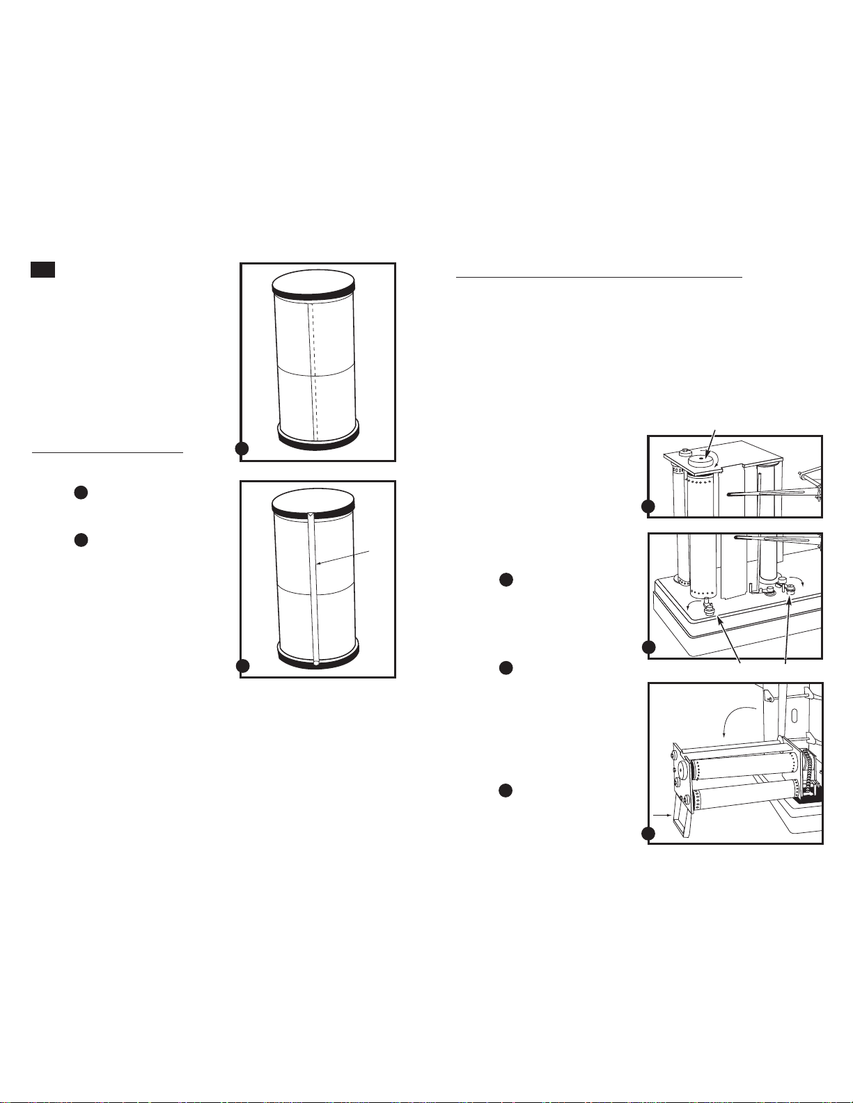
4.4
Chart paper
NOTE: See pages 13-17 for directions on
changing the chart paper on long-cycle
model 37250-20.
Your cylinder drum comes with one sheet
of chart paper already attached. See the
“Accessories” section on page 26 to order
extra chart paper.
To replace chart paper
for models 08369-50,
08369-50, 37250-10, 37250-00:
1. Wind the new chart onto the cylinder so
that the two ends of the paper overlap.
See figure
2. Secure this overlapping section with the
See figure
3. Make sure the markings on the paper
4. Follow directions on bottom of page 11
A
paper holder.
B
coincide where the overlap occurs.
to set the correct time.
To replace chart paper for long-cycle model 37250-20:
The long-cycle hygrothermograph comes with one roll of paper installed. As the
unit records, paper moves from the Chart Roll to the Take-Up Roll. When the paper is
completely used, you need to replace the chart paper.
NOTE: do not discard cardboard tube from the original chart paper roll. You will
need this cardboard tube for use on the Take-Up Roll.
For best results, we recommend you use our chart paper. See the “Accessories”
section on page 26 to order extra chart paper rolls.
When the chart paper is nearing the end of its cycle, a red stripe will appear on the
lower edge of the chart paper. The stripe means there are only three days left, and
that the paper should be changed by that time.
A
To change the chart paper:
1. Remove the protective cover. Pull the
pen lift lever towards you so the pen
tips do not touch the paper. Write the
time and date on the chart paper.
A
2. Wind the old chart paper onto the
Take-Up Roll by turning the Timing
Roll knob clockwise (in the direction
of the arrow).
See figure
A
3. Release the right and left chart
assembly locks located on the base
of the instrument near the chart
drive mechanism.
B
See figure
B
B
Timing roll knob
Chart assembly locks
4. Pull the chart assembly back using
the handle located behind the chart
assembly. To prevent the unit from
tipping over, hold the base of the
instrument with your other hand.
Use the handle to keep the chart
assembly in a horizontal position.
See figure
Find Quality Products Online at: [email protected]
www.GlobalTestSupply.com
C
C
1312
Page 8
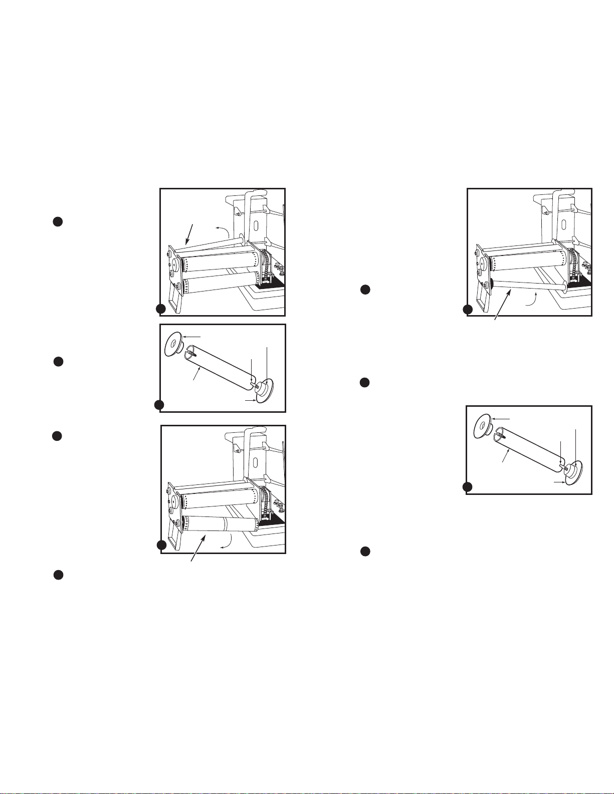
5. Remove the empty cardboard tube
from the Chart Roll (see sticker on
top of chart assembly for position).
See figure
• Push the Chart Roll towards the top
• Pull the Chart Roll out from the
• Remove the upper plastic disk of
• Remove the cardboard tube from the
See figure
D
of the chart assembly, which removes
it from the groove at the base of the
assembly.
bottom.
the Chart Roll by turning it
counter-clockwise.
metal spindle (spindle is inside the
cardboard tube). Save this cardboard
tube for step 7.
E
6. Remove the Take-Up Roll with
the old chart paper from the chart
assembly (see sticker on top of
chart assembly for position).
See figure
• Push the Take-Up Roll toward the
• Pull the Take-Up Roll out from the
• Remove the upper plastic disk of
• Remove the used chart paper,
See figure
F
top of the chart assembly, which
removes it from the groove at the
base of the assembly.
bottom.
the Take-Up Roll by turning it
counter-clockwise.
complete with inner cardboard tube,
from the metal spindle(spindle is
inside the cardboard tube).
E
D
E
F
Chart roll
cardboard
tube
Take-up roll
upper disk
lower disk
slot
stopper
7. Replace the Take-Up Roll with the
empty cardboard tube into the
chart assembly.
• Place the empty cardboard tube
(from step 5) back over the metal
spindle of the Take-Up Roll. Make sure
that the slot on the Take-Up Roll fits
into the ridge on the lower disk.
• Replace the upper plastic disk of the
Take-Up Roll by turning it clockwise.
See figure
• Place the pointed spindle tip
See figure
E
(protruding through the upper disk)
into the receptacle at the left (on the
upper part of the assembly). Push to
the left, and reinsert the right end of
the take-up cylinder into the bottom
groove. You may have to turn the
cylinder slightly until it slides into
the groove.
G
8. Install the new chart paper on the
Chart Roll.
• Load the new chart paper onto the
Chart Roll, making sure that the slot
on the chart paper roll fits into the
ridge on the lower disk.
• Make sure that the chart paper is
loaded correctly. The side of the
paper with the oval-shaped sprocket
holes should be at the upper disk
(top), while the side with the round
sprocket holes should be at the lower
disk (bottom).
• Replace the upper plastic disk of the
Chart Roll by turning it clockwise.
See figure
E
G
E
Take-up roll
cardboard
tube
upper disk
lower disk
stopper
slot
1514
Find Quality Products Online at: [email protected]
www.GlobalTestSupply.com
Page 9
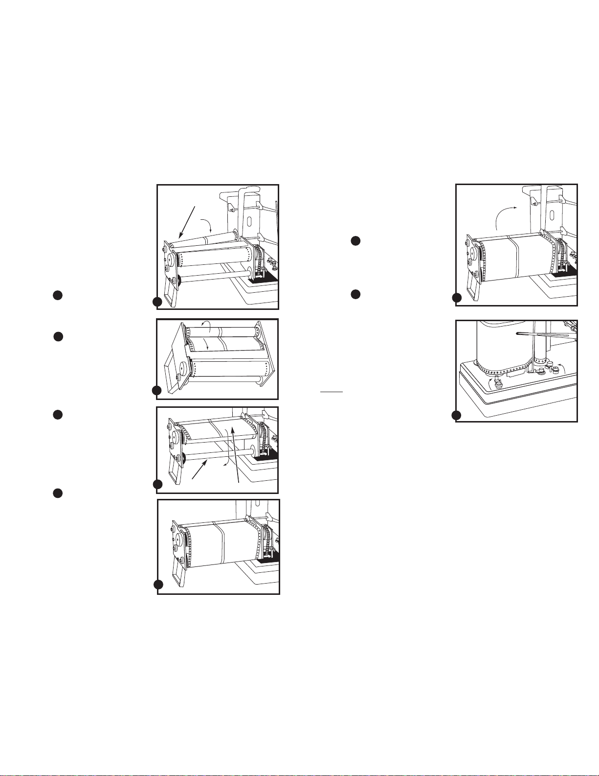
9. Install the Chart Roll with the new
chart paper back into the chart
assembly.
• Place the pointed spindle tip (protruding through the upper disk) into
the receptacle at the left (on the
upper part of the assembly). Push to
the left, and reinsert the right end of
the starting roll into the groove (on
the lower part of the assembly). Make
sure that the roll is securely installed
and can pivot easily.
See figure
• Make sure paper is positioned so
See figure
H
it will run in a counterclockwise
direction around the Chart Roll.
I
10. Pull out the chart paper about 6
inches. Draw the paper around the
Timing Roll. Make sure the sprocket holes in the paper are placed
correctly over the sprockets on the
Timing Roll.
See figure
J
11. Tape the end of the chart paper to
the Take-Up Roll. Remove any other
paper that might still be attached
to the Take-Up Roll. Be sure the
paper is straight and even so that it
tracks properly.
See figure
K
12. Advance the chart with the timing
Chart roll
knob.
13. Return the chart assembly upright
to its original position.
See figure
L
14. Tighten the right and left assembly
locks to hold chart assembly in
place.
H
See figure
M
L
15. To set time, see bottom of page 11.
16. Make sure to check that pen car-
tridges and batteries are still fresh.
I
J
Take-up roll
Timing roll
Notes
Be sure to check at least once a month
to guarantee accuracy, since the instrument operates over a long period of
time (30 or 90 days).
Also make sure to periodically check
that the pens are operating correctly.
Vibrations could loosen the chart paper
in about 60 days. The paper should be
tightened for accurate time readings.
M
K
1716
Find Quality Products Online at: [email protected]
www.GlobalTestSupply.com
Page 10
4.5
+
-
+
-
T
E
M
P
.
H
U
M
I
D
.
A
D
J
U
S
T
.
A
D
J
U
S
T
.
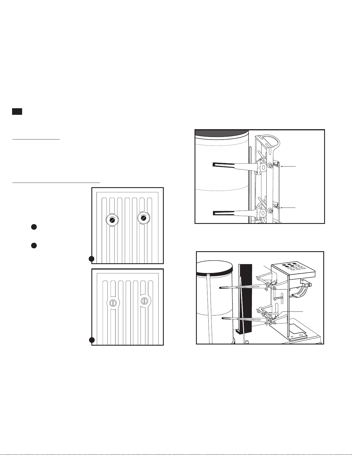
Calibration adjustment
Your hygrothermograph is factory calibrated. However, vibration during shipment
may make a slight readjustment necessary.
To adjust calibration:
1. Compare the hygrothermograph reading to another temperature/ humidity
instrument known to be accurate.
2. Raise and lower the reading by turning the adjustment screws.See drawings on
these two pages for location of the adjustment screws.
Calibration adjustment screw locations
Minidrum hygrothermograph
(model 08369-70)
On the minidrum hygrothermograph
model, the calibration screws are located behind the two stickers on the back
of the beige case protecting the pen
mechanism.
See figure
Remove the stickers to reach the calibration adjustment screws.
See figure
A
B
Domed minidrum hygrothermograph
(model 08369-50)
All other models
(models 37250-00, -10, -20)
Temperature
calibration
adjustment
screw
Humidity
calibration
adjustment
screw
A
Temperature calibration
adjustment
screw
Humidity
calibration
adjustment
screw
B
1918
Find Quality Products Online at: [email protected]
www.GlobalTestSupply.com
Page 11
4.6
Z
=
1
8
1
6
8
H
Z
=
2
2
2
4
H
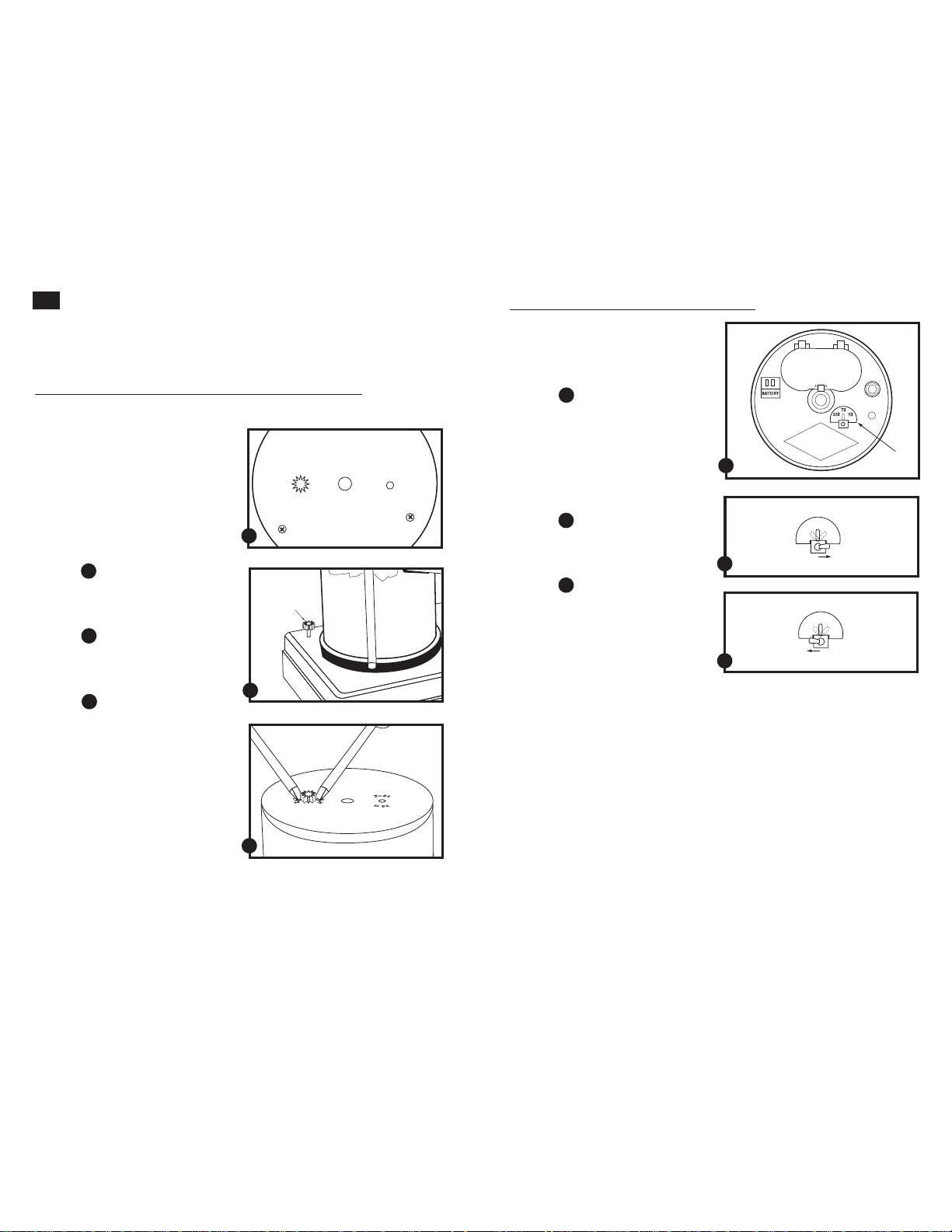
Changing drum rotation length
NOTE: Minidrum models 08369-50 and 08369-70 operate on a 7 day rotation only.
Long cycle model 37250-20 accepts either 1 month or 3 month chart rolls—it is not
necessary to adjust drum speed.
Spring wound, two speed hygrothermograph 37250-10
This model lets you select between a
1 and 7 day drum rotation. When you
receive your hygrothermograph from the
factory, it is set for a 7 day rotation.
IMPORTANT: make sure you have the
appropriate chart paper for the rotation
speed you select. See page 26 to order
more chart paper.
1. Look at the bottom of the cylinder
drum. You will see notches for two
gears. Only one gear will be in place.
See figure
A
2. The alternate gear is located on a post
at the corner of the thermohygrometer’s base. Remove it from the post.
See figure
B
3. Using two screwdrivers, lift the gear
currently installed on the bottom of
the cylinder drum.
See figure
C
4. Insert the other gear onto the oppo-
site shaft on the bottom of the drum.
• The one-day gear slides on the shaft
marked “24 H / Z = 22”. This gear has
22 teeth and a larger diameter than the
7-day gear.
• The seven day gear slides onto the
shaft marked 168H / Z = 18. This gear
has 18 teeth.
5. Place the gear not in use over the
post at the corner of the thermohygrometer’s base for storage.
6. Install the cylinder drum onto
the cylinder shaft. See page 7 for
directions.
A
B
C
Three speed hygrothermograph 37250-00
This model lets you select between a
1, 7, and 32 day drum rotation. When
you receive your hygrothermograph
from the factory, it is set for a 7 day
rotation.
See figure
IMPORTANT: make sure you have the
appropriate chart paper for the rotation
speed you select. See page 26 to order
more chart paper.
1. To switch from 7 day operation to
See figure
2. To switch from 7 day operation to
See figure
D
1 day operation, flip the switch on
top of the cylinder drum to 1D.
E
32 day operation, flip the switch on
top of the cylinder drum to 32D.
F
D
E
F
7D
1D
32D
7D
1D
32D
2120
Find Quality Products Online at: [email protected]
www.GlobalTestSupply.com
Page 12
5. Installing optional axial fan
NOTE: The axial fan is not for use with minidrum models 08369-50 and 08369-70.
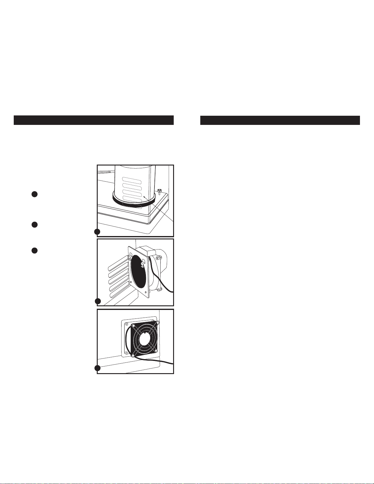
The external draft fan (optional) attaches to the protective cover. It improves instrument response and accuracy by directly pulling surrounding air into the instrument.
Use the fan in areas where ventilation is poor.
If you want to order an axial fan, see the “Accessories” section on page 26.
To attach the fan:
1.
Install the fan on the single
column of five vents located on
the protective cover.
See figure
2. Position fan so that the spring clips
See figure
3. Let the fan slide down until it stops.
See figure
4. Position the instrument so the
5. Plug the power cord into an 110 to
A
on the fan go into the upper vent
slots on the hygrothermograph
cover.
B
Make sure both spring clips are fully
engaged in the cover.
C
flow of air from the fan will not
be blocked.
120 volt, 50/60 Hz outlet. For 220 V
operation, order optional 220 V
transformer (sold separately in
“Accessories” section on page 26).
A
B
6. Precautions
1. Do not use your hygrothermograph:
• in direct sunlight
• in temperatures below –20°C or above 50°C
• near ovens, stoves, or other heating equipment
• near harsh chemicals such as paint thinner or ammonia
• in dusty or wet environments
• within magnetic fields
• in areas with strong vibrations, such as loudspeakers or motors
2. For best results, use only the pens and chart paper listed under the “Accessories”
section of this manual (page 26). We cannot guarantee results with other pens
and other paper.
3. Do not repair the instrument yourself. Should repairs be necessary, please return
the instrument to place of purchase. See the back cover of this manual for information on instrument Warranty and Return of Items.
4. If your instrument will not be used for long periods of time, make sure to replace
the pen caps and remove the battery.
C
2322
Find Quality Products Online at: [email protected]
www.GlobalTestSupply.com
Page 13
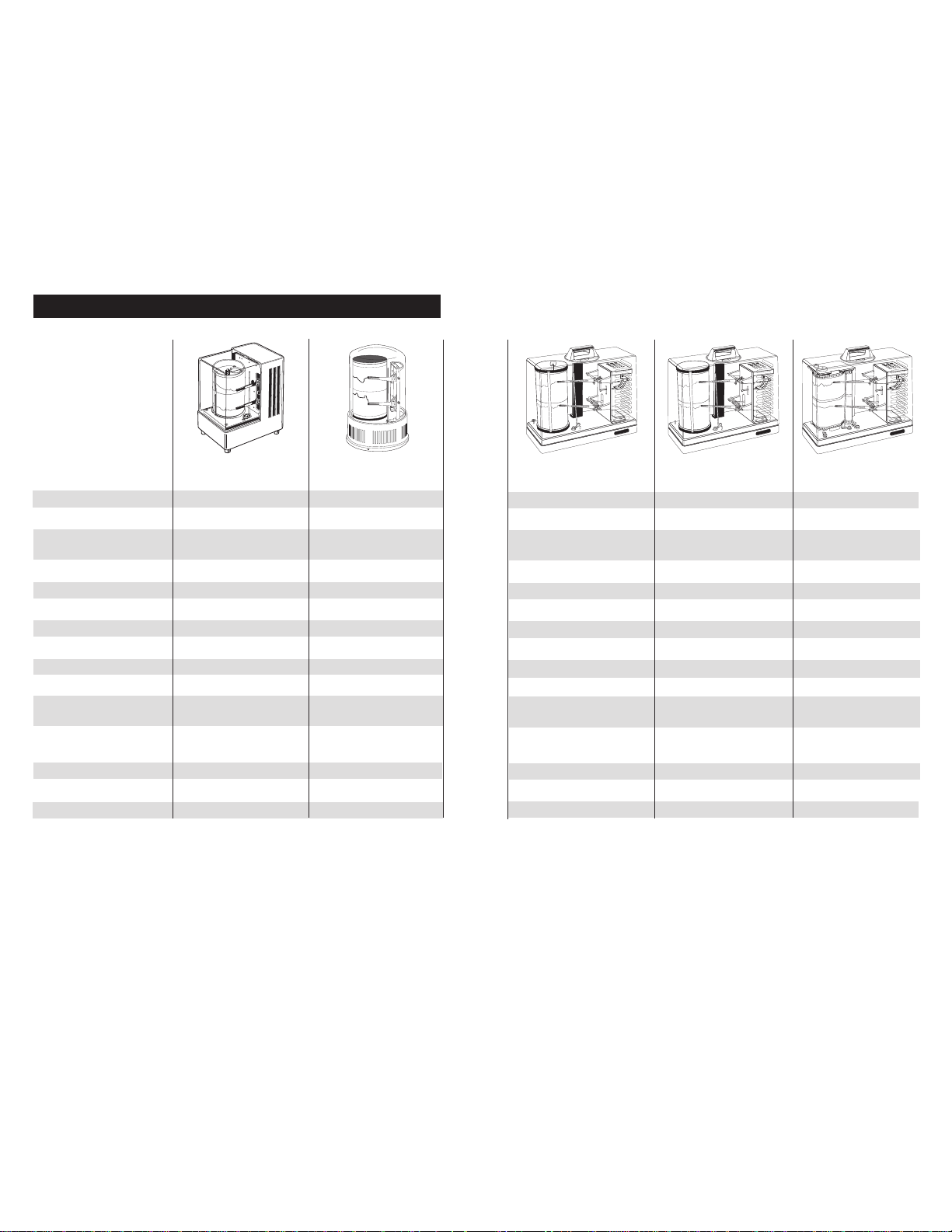
7. Specifications
Model Minidrum Domed minidrum
hygrothermograph hygrothermograph
Model number 08369-70 W08369-50
Humidity range 5 to 90% RH 5 to 90% RH
Humidity accuracy ±5% from 10 to 90% RH; ±5% from 10 to 90% RH;
±7% from 5 to 10% RH ±7% from 5 to 10% RH
Humidity chart range 5 to 100% RH 5 to 100% RH
Humidity sensor human hair bundle human hair bundle
Humidity chart graduations 5% RH 5% RH
Temperature range –6 to 40°C / 22 to 104°F –6 to 40°C / 22 to 104°F
Temperature accuracy ±2°C / ±3.6°F ±2°C / ±3.6°F
Temperature sensor bimetallic strip bimetallic strip
Temp. chart graduations 2°C / 2°F 2°C / 2°F
Chart size 3.6"H x 8.1"L 3.6"H x 8.1"L
Chart rotation 7 day (172 hr) 7 day (172 hr)
Power One AA battery (included) One AA battery (included)
Dimensions 6"W x 7.4"H x 3.9"D 7.5"H x 5" dia
Shipping weight 4 lbs 4 lbs
Spring wound, two speed Three speed Long cycle
hygrothermograph hygrothermograph hygrothermograph
37250-10 37250-00 37250-20
5 to 90% RH 5 to 90% RH 5 to 90% RH
±3% from 10 to 90% RH; ±3% from 10 to 90% RH; ±3% from 10 to 90% RH;
±5% from 5 to 10% RH ±5% from 5 to 10% RH ±5% from 5 to 10% RH
0 to 100% RH 0 to 100% RH 0 to 100% RH
human hair bundle human hair bundle human hair bundle
1% RH 1% RH 1% RH
–10 to 50°C / 14 to 122°F –10 to 50°C (14 to 122°F) –20 to 50°C
±1°C / ±1.8°F ±1°C / ±1.8°F ±1°C
bimetallic strip bimetallic strip bimetallic strip
1°C / 2°F 1°C / 2°F 1°C
6.6"H x 11.5"L 6.6"H x 11.5"L 6.6"H x 114" L (1-month)
6.6"H x 300" L (3-month)
1 day (26 hr) or 1 day (26 hr), 7 day (172 hr) 1-month (38 day max) or
7 day (172 hr) or 32 day (810 hr) 3-month (100 day max)
Spring wound Two C batteries (included) One C battery (included)
13.3"W x 11.5"H x 5.1"D 13.3"W x 11.5"H x 5.1"D 13.3"W x 11.5"H x 5.1"D
9 lbs 9 lbs 9 lbs
24 25
Find Quality Products Online at: [email protected]
www.GlobalTestSupply.com
Page 14

8. Ordering information
9. Appendix 1: Readings in areas with high humidity
Additional Hygrothermographs
WD-08369-70 Minidrum hygrothermograph
WD-08369-70 Domed minidrum hygrothermograph
WD-37250-10 Spring wound, two speed hygrothermograph
WD-37250-00 Three speed hygrothermograph
WD-37250-20 Long cycle hygrothermograph
Extra Chart Paper
Model Use with Temperature Rotation Increments Quantity/
number model type range pack
WD-08369-60 Mini-drum 22 to 104°F 7-day 2-hour 100
WD-08369-55 Mini-drum –6 to 40°C 7-day 2-hour 100
WD-08368-10 2- or 3-speed 14 to 122°F 1-day 15-minute 100
WD-08368-20 2- or 3-speed 14 to 122°F 7-day 2-hour 100
WD-08368-30 2- or 3-speed –10 to 50°C 1-day 15-minute 100
WD-08368-40 2- or 3-speed –10 to 50°C 7-day 2-hour 100
WD-08368-22 3-speed 14 to 122°F 32-day 6-hour 25
WD-08368-42 3-speed –10 to 50°C 32-day 6-hour 25
WD-37250-60 Long cycle –20 to 50°C 1-month 2-hour 1 roll
WD-37250-62 Long cycle –20 to 50°C 3-month 2-hour 1 roll
Extra Pens
For use with all OAKTON hygrothermographs.
WD-08368-75 Blue pens, 6/pack
WD-08368-70 Red pens, 6/pack
The specially processed human hair bundle, such as the one used in this instrument,
is the best sensor for ambient humidity measurements in terms of linearity,
repeatability, and temperature compensation. Human hair will elongate linearly as
humidity increases or decreases in the range of 5 to 90% RH.
However, one of the characteristics of human hair is that exposure to humidity
levels above 90%RH causes it to undergo a change of state. This condition is called
the “saturated state”, and occurs with even short exposure to high humidity levels.
When the hair bundle reaches the saturated state, it contracts and causes a 7 to 9%
downward shift in the humidity indications. If the humidity then stays below 80%,
the hair bundle will elongate linearly for approximately two weeks. After this time
period, the hair bundle is in its dry state.
The hair bundle has two curves, depending on the state of the hair bundle. These
characteristics can be taken into account when using the instrument. The instrument
is calibrated at the factory with the hair bundle in the dry state. Generally, the
instrument is used indoors with humidity levels below 90%.
When used in air conditioned areas or other areas of moderate humidity, you do not
need to adjust the instrument.
How to use the instrument in high humidity areas:
For use above 85% RH, turn the humidity fine adjustment screw counterclockwise
to raise the humidity reading by 7 to 9%. Readings will be within specifications over
the entire range when the instrument is exposed to high humidity conditions (85 to
100%) at least once every two weeks.
Note any calibration change either on the chart paper or on the instrument itself.
This way you can change the instrument back to its original calibration if required.
Axial Fan
WD-37250-50 Optional axial fan. Use with 2-speed, 3-speed and long cycle models
for more uniform sample measurements in fluctuating environments. 110 VAC
WD-01578-02 Transformer. Use to operate axial fan at 220 VAC, 100 W
26
Find Quality Products Online at: [email protected]
www.GlobalTestSupply.com
27
 Loading...