

Page 1
Quick Guide
Bench 2700 Series
pH/mV/Ion/Conductivity/TDS/Salinity/
Resistivity/Dissolved Oxygen/ºC/ºF
Part of Thermo Fisher Scientifi c
n
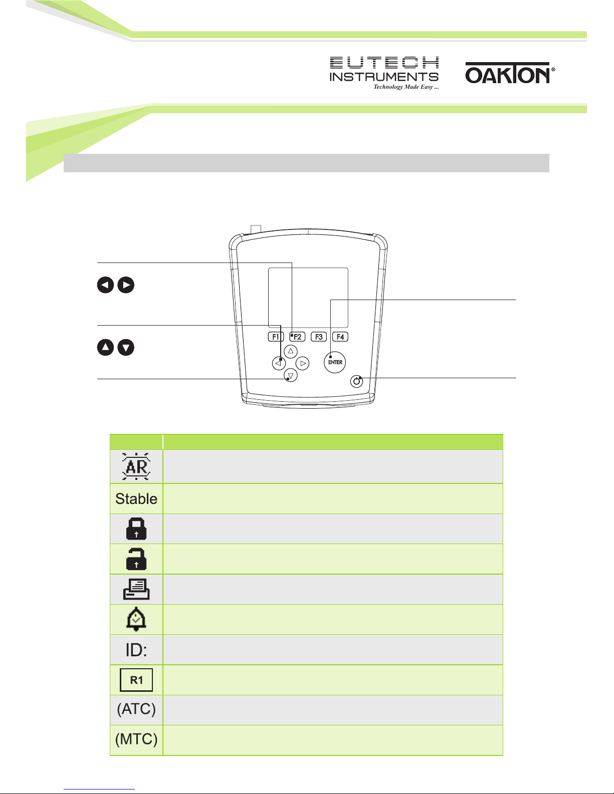
Keypad And Display
GETTING STARTED
Keys Functions
Auto Read is enabled. When fl ashing, the instrument has detected a ‘Stable’
reading and locked the value. Press MEAS to resume live reading. To disable
this feature go to SETUP…SYSTEM…AUTO READ.
Based on the stability criteria settings in System Setup, the instrument has
detected a stable reading.
Password Protection: Enabled.
Requires password for all calibration and setup menus.
Password Protection: Disabled.
No password required for any menu.
Print Setting Timed interval is active; data is being output at regular intervals.
“High Alarm”, “Low Alarm”, or “Cal Due” alarm limit had been reached.
High/Low alarms also have an audible notifi cation.
Sample ID: User selectable fi ve digit number to identify samples.
Measuring Range # of displayed value (1 thru 5). Applicable to Conductivity,
TDS, Salinity, or Resistivity measurements only.
Automatic Temperature Compensation is active; temperature is being actively
acquired with attached electrode. ATC is recommended.
Manual Temperature Compensation is active. A temperature sensor may not
be attached so the default temperature is used.
POWER: Turns the meter on and
off . Upon power on, the meter
automatically begins in the mode
that was last used. Calibration and
memory values are retained even
if meter is unplugged. The time is
displayed during power off .
Up/Down: Use to modify values in
Setup & Calibration modes.
Soft Function Keys (F1, F2,
F3, F4): Function varies.
Operation corresponds to
highlighted tab directly above
in the display.
ENTER: Use to accept selection
or con rm value. In Setup mode,
con rms selection of modi ed
values. In Calibration mode,
con rms calibration values.
Left/Right: Navigates available
Tabs in Measurement mode. Moves
cursor during certain setup modes.
18
Page 2
Use the System Setup to customize operation of your 2700 series meter. Press
measurement screen and then press ENTER when SYSTEM is highlighted to access these settings.
The following settings can be customized for each model:
n
Stability
To aid with measurement and calibration, your meter has a unique feature that provides an
obvious visual indication when the reading becomes stable. If the Stability feature is enabled,
the digits on the primary reading will be faded when unstable, becoming solid when stable.
If this feature is disabled, the primary reading will always be solid.
n
Stability Criteria
The 2700 allows adjustment of the Stable indicator which relates to how fast and frequent it
appears. There are three levels of adjustment; SLOW, MEDIUM, & FAST.
To display a ‘Stable’ reading more quickly and more often, use “FAST” setting. MEDIUM or SLOW
is recommended for most applications. When Auto Read is enabled, a stability criteria setting of
“SLOW” is recommended to for best results.
SLOW: The Stable indicator will take longer to appear and will appear less frequently. Use this
setting if you want the best results and don’t mind waiting longer to get them.
MEDIUM: This is the factory default setting. It provides a balanced response which works best for
most applications.
FAST: The Stable indicator will appear quickest of any setting. If you find that the Stable indicator
frequently appears and disappears, you may want to select a slower setting. This setting is not
recommended when AUTO READ is enabled. It is also not suitable for most non-refillable
electrodes which are generally slower to respond.
n
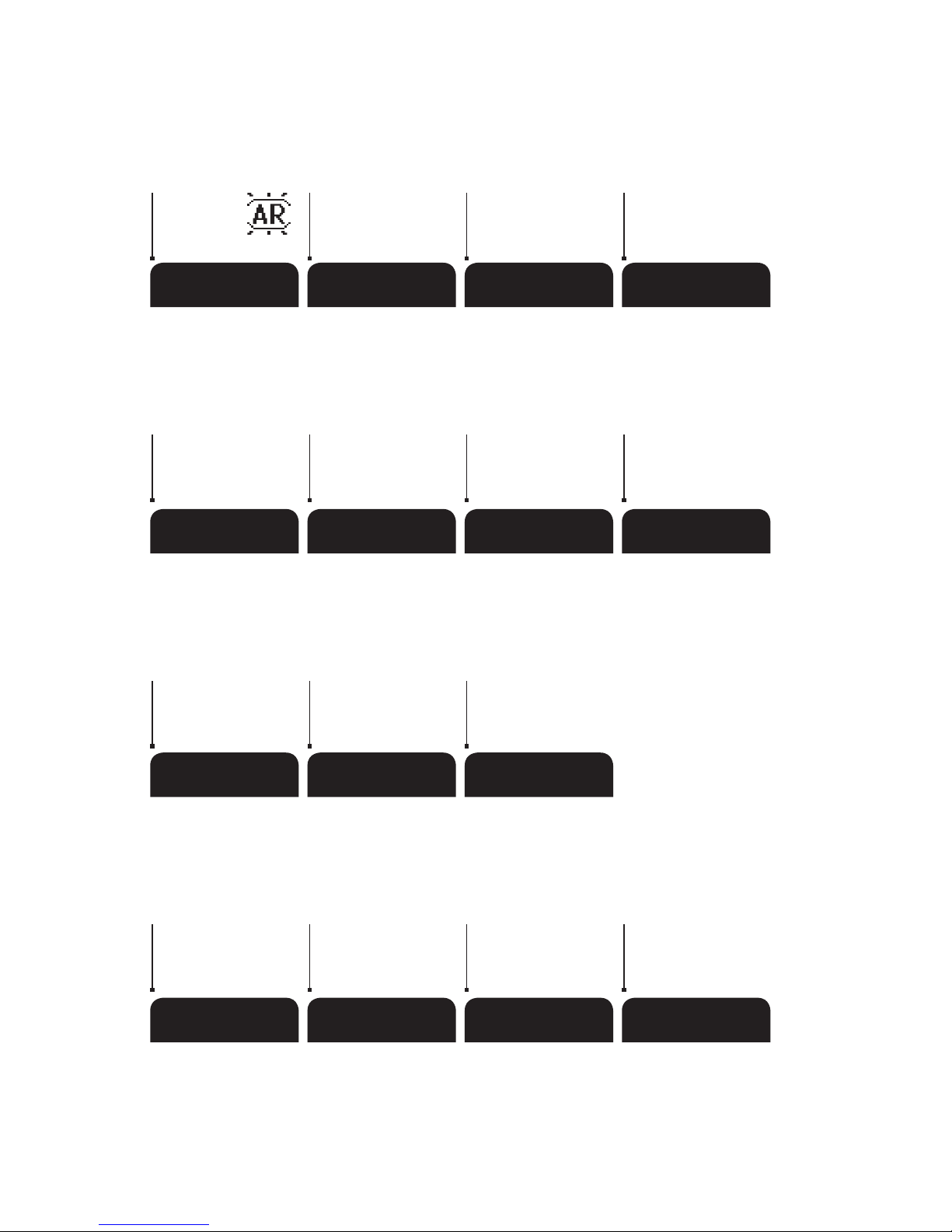
Navigation Of Tabs
SYSTEM SETUP & CONFIGURATION
PREV NEXT ESC
Scroll to previous
menu option
ESCAPE – Use to
cancel or exit out of
current screen
Scroll to next
menu option
SETUP MEM IN MEM OUT REPORT
Enters Setup mode;
use to change
System settings or
measurement parameters
Access stored values
in memory
Inserts measured value
into memory
Access Calibration
Report Data
TEMP SORT CLR–C NEXT–P
Access Temperature
Calibration
Clears current
calibration
Sorts stored data
(memory out) by
selected available
option
Skip to Next Page /
Next Parameter
of menu
MEAS CAL MODE PRINT
Resumes live
measurement
when Auto
Read is ashing
Toggles available
measurement modes
Begin Calibration
Mode using current
measured value
Sends data to
printer or PC
Page 3
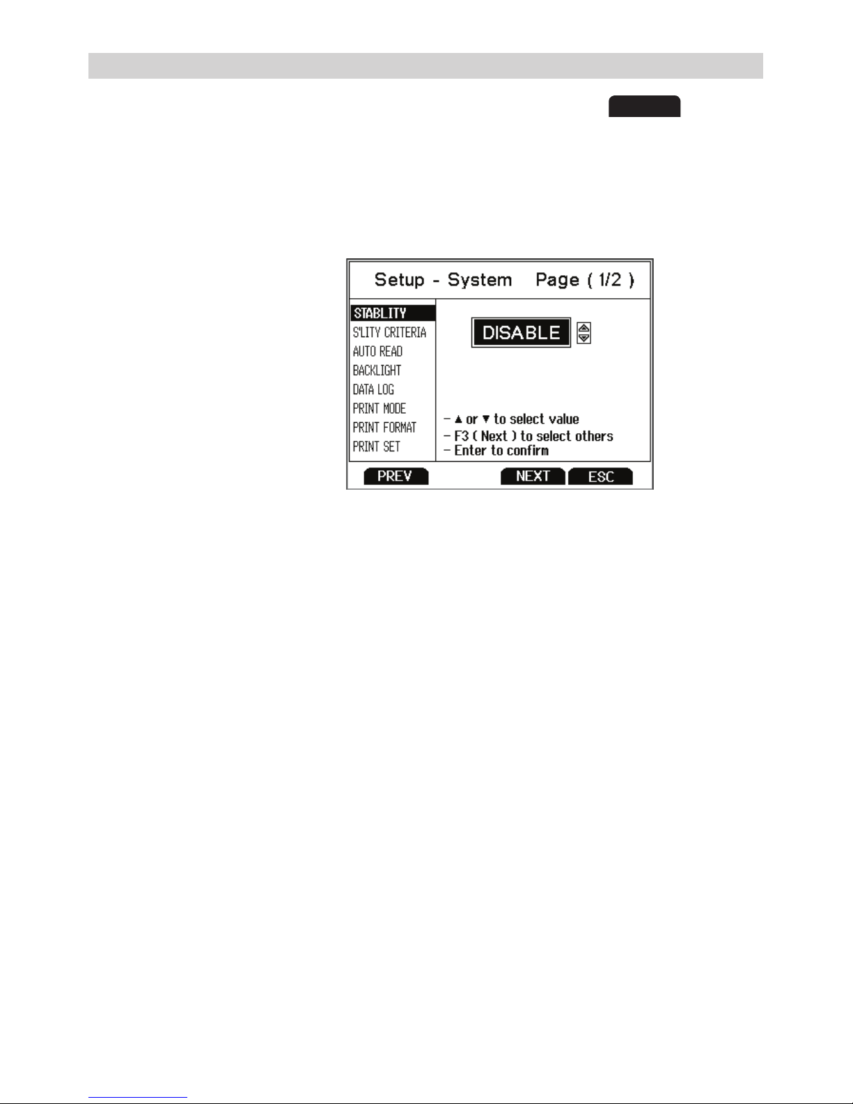
Use the System Setup to customize operation of your 2700 series meter. Press
SETUP
from the
measurement screen and then press ENTER when SYSTEM is highlighted to access these settings.
The following settings can be customized for each model:
n
Stability
To aid with measurement and calibration, your meter has a unique feature that provides an
obvious visual indication when the reading becomes stable. If the Stability feature is enabled,
the digits on the primary reading will be faded when unstable, becoming solid when stable.
If this feature is disabled, the primary reading will always be solid.
n
Stability Criteria
The 2700 allows adjustment of the Stable indicator which relates to how fast and frequent it
appears. There are three levels of adjustment; SLOW, MEDIUM, & FAST.
To display a ‘Stable’ reading more quickly and more often, use “FAST” setting. MEDIUM or SLOW
is recommended for most applications. When Auto Read is enabled, a stability criteria setting of
“SLOW” is recommended to for best results.
SLOW: The Stable indicator will take longer to appear and will appear less frequently. Use this
setting if you want the best results and don’t mind waiting longer to get them.
MEDIUM: This is the factory default setting. It provides a balanced response which works best for
most applications.
FAST: The Stable indicator will appear quickest of any setting. If you find that the Stable indicator
frequently appears and disappears, you may want to select a slower setting. This setting is not
recommended when AUTO READ is enabled. It is also not suitable for most non-refillable
electrodes which are generally slower to respond.
SYSTEM SETUP & CONFIGURATION
STABILITY
STABILITY CRITERIA
AUTO READ
BACKLIGHT
DATALOG
PRINT SETUP
PRINT FORMAT
PRINT SET
DATE & TIME
PASSWORD
CLEAR DATALOG
FACTORY RESET
CONTRAST
32
Page 4

n
Auto Read
If AUTO READ is enabled, the measured value will automatically lock when the Stable
indicator appears. A flashing “AR” icon confirms this condition. To resume a live reading
again, it is necessary to press MEAS each time Stable appears. Disable this feature to
continuously view the active reading.
n
Backlight
Select “PERMANENTLY ON” on to keep the backlight on at all times that the meter is powered on.
This will offer the best visibility but consumes the most power.
Select “ON WITH KEY PRESS” to turn on the backlight for a specified time after any key press.
Select “0” to keep the backlight off at all times that the meter is powered on.
n
Data Log (Storing Data To Internal Memory)
Select “SINGLE” to manually save one point at a time. Press the “MEM IN” function key any time
during measurement to save data.
Select “TIMED” to automatically save data at selectable intervals – ranging from 3 to 3600 seconds.
Data will be collected until the data limit is reached or until “SINGLE” data log is selected. This
feature is useful for gathering data from a single sample over time. Note that “MEM IN” is not
available during TIMED setting. As data is collected, the display will indicate how much memory
has been used.
To view stored data, use “MEM OUT”. Note: the more data that has been acquired memory, the
longer the data will take to display.
n
Print Setup
Adjust the RS-232 output settings for baud rate, parity, data bit, and stop bit to match your printer
or computer settings as necessary.
n
Print Format
When utilizing the RS-232 output; choose “TEXT/PRINTER” option to send the data in an easily
viewable format – best for printing.
Choose “CYBERCOMM” option to send the data as a comma separated value (CSV) – best for
exporting data into spreadsheet software.
n
Print Set
This is identical to the Data log function, but data is sent via RS-232 output instead of
internal memory.
Select “SINGLE” to manually output one value at a time – best for printing or collecting data to
your PC from many samples.
Select “TIMED” to automatically output live data at selectable intervals – ranging from 3 to 3600
seconds. Data will be output until “SINGLE” Print set is selected. This feature is most useful for
gathering data for use with software. Unlike the Data Log setting, data can be saved to memory
using “MEM IN” during TIMED setting.
n
Date & Time
Setting the correct date and time is required for GLP and will apply to power off, measurement,
data log, and print functions. Instrument has battery backup to retain date/time settings upon
power loss. Factory reset will not apply to date and time setting once it has been set. Changes
related to daylight savings time must be manually entered.
Date Format : Select (MM DD YY) or (DD MM YY)
Time Format : Select 12 Hrs (AM/PM) or 24 Hrs
n
Password
Select “ENABLE” to restrict access to Calibration and Setup modes. When password protection is
enabled, password entry is required before performing any calibration, or making changes to the
setup mode. Setup parameters can be viewed, but can not be changed without correct password
entry. The password is a user selectable number from 1 to 99999.
Select “DISABLE” if password protection is not desired.
The meter does not allow you to edit setup parameters or perform a new calibration unless you
enter the correct password. If an incorrect password is entered 3 consecutive times, the meter
returns to measurement mode.
In the event the password can not be recovered, a password can be provided via a written request
to Eutech Instruments/Oakton Instruments. The instrument serial number and your contact
information are required.
n
Clear Datalog
Select “YES” to delete all saved data that was manually or automatically stored into memory.
This step is most commonly required when the “TIMED” data log interval is not turned off and as
a result, fills the memory to capacity. When the memory is full, deleting the saved data is required
in order to save additional data. The 2700 will never erase old data in favor of new data when the
memory is full.
If you wish to view, print or send the saved data to a PC before deleting, use the “MEM OUT”
function from measurement mode.
n
Factory Reset
Select “YES” to reset the 2700 to the factory default settings except; Date & Time, Temperature
calibration, and data stored in memory.
n
Contrast Adjustment
Optimize the contrast setting of your 2700 display for best visibility in your surrounding lighting
conditions. Test various contrast settings for best results. This setting will be applied to both
backlight and non-backlight conditions.
Page 5

n
Date & Time
Setting the correct date and time is required for GLP and will apply to power off, measurement,
data log, and print functions. Instrument has battery backup to retain date/time settings upon
power loss. Factory reset will not apply to date and time setting once it has been set. Changes
related to daylight savings time must be manually entered.
Date Format : Select (MM DD YY) or (DD MM YY)
Time Format : Select 12 Hrs (AM/PM) or 24 Hrs
n
Password
Select “ENABLE” to restrict access to Calibration and Setup modes. When password protection is
enabled, password entry is required before performing any calibration, or making changes to the
setup mode. Setup parameters can be viewed, but can not be changed without correct password
entry. The password is a user selectable number from 1 to 99999.
Select “DISABLE” if password protection is not desired.
The meter does not allow you to edit setup parameters or perform a new calibration unless you
enter the correct password. If an incorrect password is entered 3 consecutive times, the meter
returns to measurement mode.
In the event the password can not be recovered, a password can be provided via a written request
to Eutech Instruments/Oakton Instruments. The instrument serial number and your contact
information are required.
n
Clear Datalog
Select “YES” to delete all saved data that was manually or automatically stored into memory.
This step is most commonly required when the “TIMED” data log interval is not turned off and as
a result, fills the memory to capacity. When the memory is full, deleting the saved data is required
in order to save additional data. The 2700 will never erase old data in favor of new data when the
memory is full.
If you wish to view, print or send the saved data to a PC before deleting, use the “MEM OUT”
function from measurement mode.
n
Factory Reset
Select “YES” to reset the 2700 to the factory default settings except; Date & Time, Temperature
calibration, and data stored in memory.
n
Contrast Adjustment
Optimize the contrast setting of your 2700 display for best visibility in your surrounding lighting
conditions. Test various contrast settings for best results. This setting will be applied to both
backlight and non-backlight conditions.
54
Page 6

ION CALIBRATION GUIDE
n
pH Calibration (Using Custom Buers)
Follow same procedure as below – differences are: 2 point minimum calibration is required, the
primary display in cal mode is manually adjusted to the desired custom buffer value, and any pH
value can be used in any order – but must be at least 1.0 pH unit apart from one another.
n
pH Calibration (Using Preset Buer Group)
1. Turn meter on, press
MODE
if needed for pH measurement mode.
2. Press
CAL
(enter password if required) to enter calibration mode.
3. Rinse the pH electrode with clean water then dip in your pH buffer – the 1st calibration value
must always be 7.00, 6.86, or 6.79 depending on the buffer group used; subsequent values can
be calibrated in any order. Use an ATC electrode for most accurate results.
4. The primary display is the un-calibrated measured value. The 2700 automatically selects the
appropriate value from your buffer group in the secondary display. This value will blink when
the ‘Stable’ indicator appears. Selecting
CLR–C
will clear the existing calibration.
5. Press
to accept calibration. The accepted value will be visible inside of a
beaker icon. % slope is visible after two calibration points have been completed.
6. Repeat steps 3 - 5 with additional pH buffers or press
ESC
to save calibration.
When the specified number of calibration points is met, the pH calibration report page is
automatically displayed.
pH CALIBRATION GUIDE
n
Ion Selective Calibration (Minimum 2-Point Required)
1. Press
MODE
for ion measurement mode. “- - - -” indicates no ion calibration
is stored. Press
CAL
.
2. Prepare two or more ion calibration standards. Rinse and dip your ISE into your lowest
calibration standard. Use up/down arrows to match the upper value to your standard
(from 0.001 to 10000).
CONDUCTIVITY CALIBRATION GUIDE
n
Conductivity Calibration (Manual Adjustment)
1. Press
conductivity standard – use lowest to highest when using multiple standards.
2. Use up/down arrows to adjust cell constant or press
(recommended). Next, adjust the value to match your standard. Press
The value, Range (R) and the new cell constant are now shown.
3. For multi-point calibration repeat with additional standards.
Press
Calibrate one point per range, up to 5 points.
n
Conductivity Calibration (Automatic Recognition)
1. Press
conductivity standard – either 84 µS, 1413 µS, 12.88 mS or 111.8 mS.
2. Use up/down arrows to adjust cell constant or press
(recommended). Press
are now shown.
3. For multi-point calibration repeat with additional standards. Press
calibration or press
up to 4 points.
3. Press
15 to 90 mV/decade and will be visible inside of a beaker icon.
4. Repeat steps 2 & 3 with the next lowest calibration standard (up to 8 standards) or
press
** Refer to your ISE manual for electrode specific instructions and care.
Page 7
CONDUCTIVITY CALIBRATION GUIDE
n
Conductivity Calibration (Manual Adjustment)
1. Press
CAL
if needed for calibration mode. Rinse electrode then dip into your
conductivity standard – use lowest to highest when using multiple standards.
2. Use up/down arrows to adjust cell constant or press
NEXT
to keep the nominal value
(recommended). Next, adjust the value to match your standard. Press
when ‘Stable’.
The value, Range (R) and the new cell constant are now shown.
3. For multi-point calibration repeat with additional standards.
Press
ESC
to save calibration or press
NEXT
to view the calibration report.
Calibrate one point per range, up to 5 points.
n
Conductivity Calibration (Automatic Recognition)
1. Press
CAL
if needed for calibration mode. Rinse electrode then dip into your
conductivity standard – either 84 µS, 1413 µS, 12.88 mS or 111.8 mS.
2. Use up/down arrows to adjust cell constant or press
NEXT
to keep the nominal value
(recommended). Press
when ‘Stable’. The value, Range (R) and the new cell constant
are now shown.
3. For multi-point calibration repeat with additional standards. Press
ESC
to save
calibration or press
NEXT
to view the calibration report. Calibrate one point per range,
up to 4 points.
3. Press
after ‘Stable’ appears. The calibration value is acceptable if it is within
15 to 90 mV/decade and will be visible inside of a beaker icon.
4. Repeat steps 2 & 3 with the next lowest calibration standard (up to 8 standards) or
press
ESC
to save the calibration.
** Refer to your ISE manual for electrode specific instructions and care.
76
Page 8
Quick Guide
Bench 2700 Series
pH/mV/Ion/Conductivity/TDS/Salinity/
Resistivity/Dissolved Oxygen/ºC/ºF
n
GETTING STARTED
For more information on our products, please contact our channel partner or visit our websites listed below:
Eutech Instruments Pte Ltd Oakton Instruments Eutech Instruments Europe B.V.
Blk 55, Ayer Rajah Crescent, 625 E Bunker Ct, P.O. Box 254, 3860 AG Nijkerk,
#04-16/24, Singapore 139949 Vernon Hills, IL 60061, USA The Netherlands Wallerstraat 125K,
eutech@thermofi sher.com [email protected] 3862 CN Nijkerk, The Netherlands
www.eutechinst.com www.4oakton.com eutech@thermofi sher.com
www.eutechinst.com
n
Concentration (ppm, mg/L) Dissolved Oxygen Calibration
1. Press
MODE
for concentration mode & rinse the probe – do not dry.
2. Dip the probe into sample of known DO concentration (i.e. determined by titration or another
instrument). Press
CAL
.
3. Use up/down arrows to adjust the upper DO reading value to match your standard. The lower
reading is the factory default value.
4. Press
after ‘Stable’ appears to accept the calibration.
n
100 % or 0 % Dissolved Oxygen Calibration
1. Press
MODE
for % mode & rine the probe – do not dry.
2. To calibrate 100 %, hold the probe facing downwards in air or dip into air saturated water.
To calibrate 0 %, dip the probe in zero oxygen solution. Press
CAL
.
3. Press
after ‘Stable’ appears to accept the calibration. Allow enough time –
0 % calibration can often take several minutes.
Tip: When calibrating both 100 % and 0 %, always perform 100 % fi rst.
DO CALIBRATION GUIDE
 Loading...