


Oakley Sound Systems
5U Oakley Modular Series
RM-4014 Ring Modulator
PCB Issue 3
User Manual
V3.0.0
Tony Allgood B.Eng PGCE
Oakley Sound Systems
CARLISLE
United Kingdom
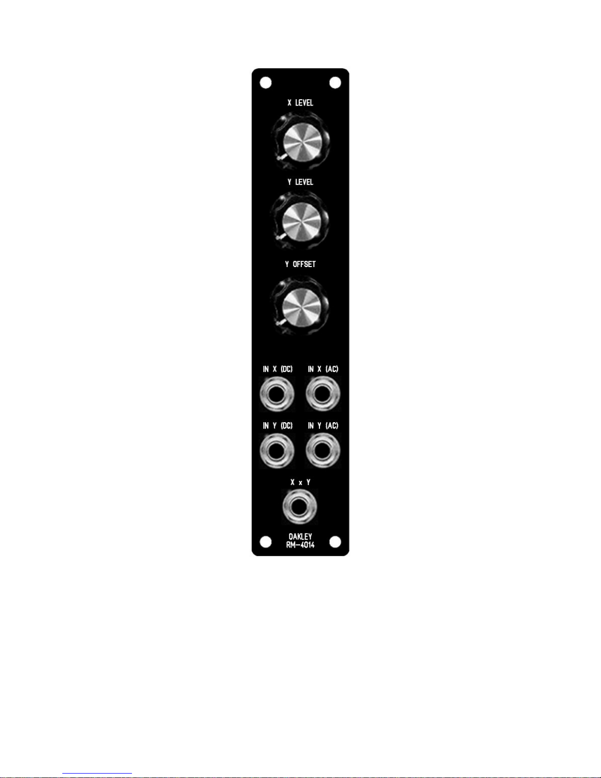
The suggested 5U panel design. Note the slightly different spacing of the knobs compared
with the usual 41mm 5U Oakley standard.
2

Introduction
This is the User Manual for the issue 3 RM-4014 Ring Modulator 5U module from Oakley
Sound. This document contains an overview of the operation of the unit and the calibration
procedure.
For the Builder's Guide, which contains a basic introduction to the board, a full parts list for
the components needed to populate the board or boards, and a list of the various
interconnections, please visit the main project webpage at:
http://www.oakleysound.com/ringmod.htm
For general information regarding where to get parts and suggested part numbers please see
our useful Parts Guide at the project webpage or http://www.oakleysound.com/parts.pdf.
For general information on how to build our modules, including circuit board population,
mounting front panel components and making up board interconnects please see our generic
Construction Guide at the project webpage or http://www.oakleysound.com/construct.pdf.
3

The Oakley RM-4014 Ring Modulator
This is a vintage ring modulator design with bags of character. It is based on the classic
ARP4014 sub-module which was used on the ARP2500 modular and ARP2600 semi-modular
synthesisers. The design has a fully discrete core but uses two op-amps for input and output
amplification.
A ring modulator has two main inputs, usually called X and Y, and one output. The output
voltage is the product of the two input voltages. In other words it multiplies the two input
signals together to produce a new and different sounding output. If you have two sine wave
input signals then the output will have both the sum and difference frequencies. For example,
if X is a 440Hz sine wave and Y a 40Hz, you would get a 480Hz and a 400Hz sine wave from
the output. However, this is only really true in a perfect ring modulator, and this ring
modulator is not that. Each input has its own differing non-linearities or imperfections. This
greatly adds to the character of the resultant output.
The Oakley Ring Modulator features three rotary control pots. Each input has its own
attenuator, and there's also a offset control for the Y input. In conjunction with the Y
attenuator, this third pot effectively acts as a wet-dry control for the X input. But because of
the non-linearities inherent in the design it also acts in more subtle ways.
You can also use the Oakley Ring Mod as a standard VCA. Just use the Y input as your CV
input and X will be shaped accordingly. Each input can be either direct coupled (DC) or high
pass filtered (AC). The former allows DC and low frequency signals to be processed. While
the latter provides a DC block to process only alternating frequencies. The standard panel
design makes both types of input available with each having its own socket. You can use both
inputs on each of the X and Y inputs at the same time. Input signals will be summed together
so you can also use the RM-4014 as a simple audio mixer.
This is the prototype issue 1 RM-4014 Ring Modulator module behind a natural finish 1U wide MOTM
format Schaeffer panel.
4

Calibration
There are three trimmers on the PCB which need adjusting correctly to get the best out of the
ring modulator module. It is important that you adjust these in your modular as the settings
are affected by the power supply voltages.
Allow the modular and ring modulator to warm up for 15 minutes.
BAL1: Turn down X LEVEL and Y LEVEL pots to their minimum settings. Turn the Y
OFFSET pot to its maximum level. Measure the output voltage from the output socket with a
good digital voltmeter. Adjust BAL1 until the output voltage is 0.000V +/- 5mV.
BAL2: Insert a triangle wave signal at 440Hz to the IN Y AC input. Turn down the Y
OFFSET pot to its minimum setting. Turn up the Y LEVEL to full. If you have a 'scope then
adjust BAL2 until the signal seen at the output socket is minimised as much as possible. It will
not go away completely. If you haven't got a scope then use your ears with your monitoring
amp turned up somewhat. Adjust BAL2 until the sound from the output socket is at its
smallest level. You will not get rid of it completely, the ring modulator is not perfect and as
such it will leak or bleedthrough. Once you have done this remember to turn your amp down if
you have turned it up high.
GAIN: Ensure that the Y LEVEL is set to minimum, but the other two pots to their
maximum. Insert an audio signal into IN X (DC) and adjust GAIN so that the output signal is
at the same level or volume as the input. That is, if you have a 5V peak signal inserted into IN
X, then you should adjust GAIN for a 5V peak signal at the output.
Once that is completed the unit is ready to be used to make music, or just daft noises...
5

Final Comments
I hope you enjoy using the Oakley Ring Modulator module.
If you have any problems with the module, an excellent source of support is the Oakley Sound
Forum at Muffwiggler.com. Paul Darlow and I are on this group, as well as many other users
and builders of Oakley modules.
If you have a comment about this user manual, or have a found a mistake in it, then please do
let me know.
Last but not least, can I say a big thank you to all of you who helped and inspired me. Thanks
especially to all those nice people on the Synth-diy and Analogue Heaven mailing lists and
those at Muffwiggler.com.
Tony Allgood at Oakley Sound
Cumbria, UK
© July 2011
No part of this document may be copied by whatever means without my permission.
6
 Loading...