

Page 1
User Manual P1
MC-5H
User Manual
Page 2
Control System
Contents
Safety Information
03
Specication 06
Connection 07
Physical Connection
16
Accessories
Assembly
09
10
17
19Package
18Service and Maintenance
User Manual P2
Page 3
WARNING!
Safety hazard.
Risk of severe
injury or death.
Refer to manual before
installing, powering
or servicing.
Hazardous voltage.
Risk of lethal or
severe electric shock.
Hot surface.
Do not touch.
Fire hazard. Emission hazardous
to eyesight.
This product is for professional use only. It is not for household use.
This product presents risks of severe injury or death due to re hazards, electric shock and falls.
Read this manual before installing, powering or servicing this product, follow the safety precautions
listed below and observe all warnings in this manual and printed on the product.
If you have questions about how to operate the tile safely, please contact your ROE supplier.
PROTECTION FROM ELECTRIC SHOCK
Connect the product to AC mains power within the range 100-240V nominal at 50 or 60 Hz only.
.
Disconnect the product from power when not in use.
Always ground (earth) the product electrically.
Before using the product, check that all power distribution equipment and cables are in perfect
condition and rated for the current requirements of all connected devices.
Do not use the product if the power cable or a power plug is in any way damaged, defective or
showing signs of overheating.
Do not attempt to open any cover.
Refer any service operation not described in this manual to a qualied technician.
01
Safety Information:
Read the safety precautions in this section before
installing, powering, operating or servicing this product.
The following sysmbols are used to identify important safety information on the product and in this manual:
WARNING! WARNING! WARNING! WARNING! WARNING! WARNING!
User Manual P3
Page 4
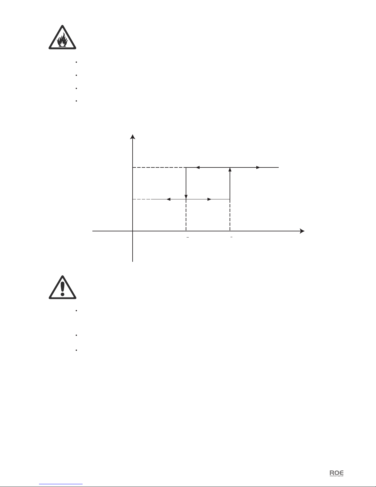
165+5
PROTECTION FROM FIRE
Do not stick lters, masks or other materials directly onto LED modules.
Do not modify the product in any way not described in this manual.
Install only genuine ROE parts in or on the product unless an alternative is described in this manual.
Create an installation by installing tiles at the top and working downwards. Disassemble an installation
by removing tiles at the bottom and working upwards.
Check that all external covers and rigging hardware are securely fastened.
Block access below the work area and work from a stable platform whenever installing, servicing or
moving the product.
Do not operate the product full load if the ambient temperature of power units (Ta) exceeds 45°C (113° F)
or less than -20°C(-4° F).
170+5
1480
2000
Pout/W
Vin/Vac
PROTECTION FROM INJURY
Important warnings
Maximum and minimum ambient temperature:
The maximum ambient temperature for the LED wall is 45 °C; the minimum temperature is (-20°C.)
User Manual P4
High leakage current:
The combination of power boxes in an installation results in increased levels of Leakage current.
In order to avoid risk of electric shock due to high leakage current, proper grounding of the installation
is required.
Page 5
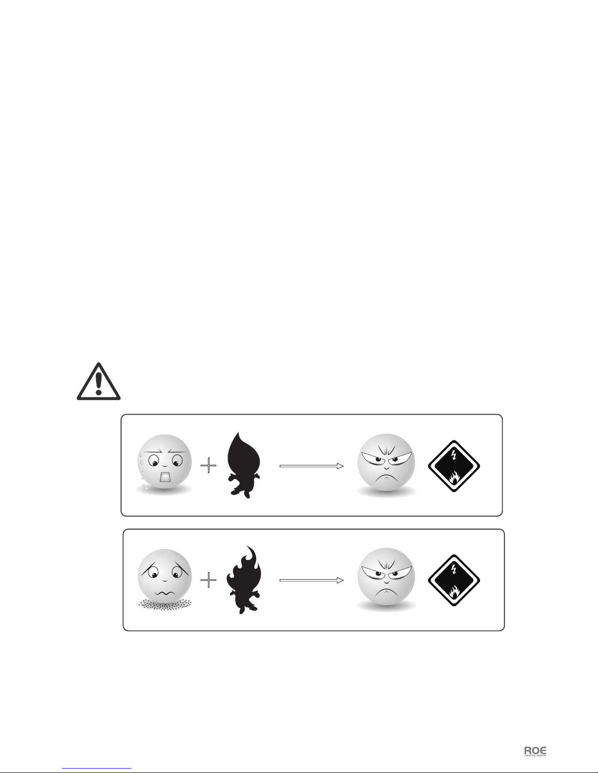
FRAME PROTECTION
Water>150°C
FirePowder
Danger
Danger
Note: At normal temperature environment, Magnesium alloy is abosolutely stable and safe.
It’s dangerous only in:
1. Temperature higher than 150°C with water;
2. Powder with re.
Mg
Mg
Mg
Mg
Data cables:
The data cables provided with this system have special properties for safety. They are not user serviceable.
If the data cables are damaged, replace them only with new ones. Never try to repair a data cable. Per
requirements of the National Electrical Code in the USA, the length of a data cable must not exceed 100 m
(332 feet). Avoid exposure of data cables to accidental contact with lightning or power conductors.
®
MC-5H(HB) LED tiles cannot be hot swapped:
Always disconnect the power cord from the control box before connecting or disconnecting the cable string
or one of MC-5H(HB) LED tiles.
Power system
Mains cords:
The power cords delivered with this system have special properties for safety. They are not user Serviceable.
If the power cords are damaged, replace them only with new ones. Never try to repair a power cord.
This equipment MUST be earthed:
In order to protect against risk of electric shock, the installation should be properly grounded. Defeating
the purpose of the grounding type plug will expose you to the risk of electric shock.
User Manual P5
Page 6
A. Horizontal Interconnect Lock
B. Frame Lock Pin
C. Indicator Light
D. Testing Button
E. Horizontal Interconnect Dowel
F. Vertical Interconnect Latch Lever
G. Vertical King Pin
H. Alignment Pin
J. Breather Valve
K. Carry Handle
L. Module Handle
M. Pothook
N. Auxiliary component(connect in vertical)
O. Fan
P. Rubber Grip
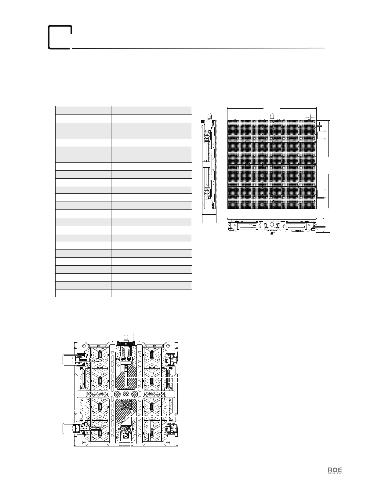
MC-5H(HB) Dimensions:MC-5H(HB) Specication:
Specification:
02
600.0
7.5
7.5
600.0
95.0
95.0
(Unit:mm)
Rear components:
IP(Front/Reverse)
LED Type
Transparency
Max. Brightness
HB Black SMD 3 in1/White SMD 3 in 1
5.769mm
Solid
23.6”×23.6”×3.7”
600.0×600.0×95.0mm
0.36m²
104×104
30,044
140°/120°
-10°/0°/+10°
17kg/37.5lbs
1/4
3840Hz
400W/280W
Scan
Processor Evision
Gray Scale
-40°~ 60°C, 10~90%RHStorage Temp/Humidity
-20°~ 45°C, 10~90%RHOperational Temp/Humidity
Pixel Pitch
Tile Size( W×H×D)
Tile Area
Pixels/Tile
Pixels/m²
Viewing Horizontal/Vertical
Weight/Tile(with frame)
10.6kg/23.4lbsWeight/Tile
Curve Angle
Max.Hanging
Max.Stacking
16bit
IP65
Refresh Rate
Max Power/Tile
5,000(Multicolor 2727)
6,000(NationStar 2727)
20 tiles
8 tiles
User Manual P6
With black LED,MC-5H(HB) have high performance on contrast and video quality. Depending on integrated
molding production and magesium alloy material, its structure is so robust and lightweight, that we can climb
and move on the LED wall directly. Installation or Maintenance is very easy. Furthermore, to protect the LED light
preferably, Mask increased the brim. Its become more safety.
G
M
J
N
B
D
C
H
L
E
P
K
A
F
O
Page 7

03
Connection
User Manual P7
Evision
AC 220V
USB
DVI
①
②
Evision
AC 220V
USB
DVI
①
②
MC-5H Built in Power Supply
Input Voltage AC 220V
Hanging System
MC-5H Built in Power Supply
Input Voltage AC 110V
1. Neither Hanging Bar nor Vertical Interconnect Latch Lever can load more than 20 tiles of MC-5H.
2. When the Input Voltage is 220V, one Power Cable can load 8 tiles of MC-5H;
and the Input Voltage is 110V, one Power Cable can load 4 tiles of MC-5H.
Notes:
AC 220V AC 220V AC 220V AC 220V AC 220V AC 220V
③
④
⑤ ⑤
⑤
⑥
⑦
AC 220V AC 220V AC 220V AC 220V AC 220V AC 220V
③
④
8 tiles high 4 tiles high
MC-5H
MC-5H
MC-5H
MC-5H
MC-5H
MC-5H
MC-5H
MC-5H
MC-5H
MC-5H
MC-5H
MC-5H
MC-5H
MC-5H
⑤
⑤ ⑤
⑥
⑦
Page 8

User Manual P8
Evision
AC 220V
USB
DVI
①
②
MC-5H Built in Power Supply
Input Voltage AC 220V
Stacking System
1. Base Bar can load no more than 8 tiles of MC-5H.
2. When the Input Voltage is 220V, one Power Cable can load 8 tiles of MC-5H; and the Input Voltage is 110V,
one Power Cable can load 4 tiles of MC-5H.
Notes:
⑦
MC-5H
MC-5H
MC-5H
MC-5H
MC-5H
MC-5H
MC-5H
MC-5H
MC-5H
MC-5H
MC-5H
MC-5H
AC 220V AC 220V AC 220V AC 220V AC 220V AC 220V
③
④④④
8 tiles high
⑥
⑤
⑤
Evision
AC 220V
USB
DVI
①
②
MC-5H Built in Power Supply
Input Voltage AC 110V
⑦
AC 220V AC 220V AC 220V AC 220V AC 220V AC 220V
③
④④④
4 tiles high
⑥
⑤
⑤
⑤
⑤
Power and Data connections of
MC-5H tiles
Data
Data Adaptpr
WeiPu
Power
Page 9

Accessories
04
User Manual P9
Name
SAP No.
Dimension
Weight
Evision
201000S0007
W480×H45×D240mm
2.3kg
:
:
:
:
Name
SAP No.
Dimension
Weight
Data Cable
208004S0194
30m
1.4kg
:
:
:
:
Name
SAP No.
Dimension
Weight
Max Capacity
Power Cable
208001S0611
10/30m
1.8kg/4.6kg
16A
:
:
:
:
:
Name
SAP No.
Dimension
Weight
Data Cable
208002S0225
0.9m
0.1kg
:
:
:
:
Name
SAP No.
Dimension
Weight
Data Adaptor
203000S0015
W56×H32×D26mm
0.1kg
:
:
:
:
Name
SAP No.
Dimension
Weight
Hanging Bar
207002S0025
W562×H100×D120mm
10.5kg
:
:
:
:
Name
SAP No.
Dimension
Weight
Hanging Bar
207002S0024
W1162×H120×D160mm
21.0kg
:
:
:
:
Name
SAP No.
Dimension
Weight
Base Bar
304010-00100
W562×H160×D90mm
7.0kg
:
:
:
:
Name
SAP No.
Dimension
Weight
Rear Support Truss
304012-00292
W1200×H50×D290mm
4.6kg
:
:
:
:
Name
SAP No.
Dimension
Weight
Rear Bridge
206002S0178
W242×H44×D177mm
1.0kg
:
:
:
:
①
② ③ ④
⑤ ⑥ ⑥⑦
Name
SAP No.
Dimension
Max.Capacity
T Dolly
206002S0132
W1295×H1560×D790mm
24 tiles of MC-5H
:
:
:
:
Name
SAP No.
Dimension
Max.Capacity
Flightcase
309003-00109
W1123×H933×D677mm
8 tiles of MC-5H
:
:
:
:
Name
SAP No.
Dimension
Weight
Base Truss
304012-00291
W1200×H80×D200mm
8.8kg
:
:
:
:
Name
SAP No.
Dimension
Weight
Base Bar
304010-00101
W1162×H160×D90mm
12.8kg
:
:
:
:
Name
SAP No.
Dimension
Weight
Windload
reinforcement beam
304012-00715
W1800×H90×D45mm
7.4kg
:
:
:
:
Name
SAP No.
Dimension
Weight
Windload
reinforcement beam
304012-00716
W1200×H90×D45mm
4.7kg
:
:
:
:
⑦
Page 10

User Manual P10
Assembly:
05
Hanging System
120mm
160mm
562mm
Hanging Bar Dimensions:
Diagram:
Hanging Installation
Case 1 Case 2
A: Ring(For hanging installation)
D: Supporting tubeB: Bolt
C: Vertical Connect Latch Lever
Note: Case 1 : Hanging bar can load 1—4 tiles of MC-5H.
Case 2 : Hanging bar can load 4—20 tiles of MC-5H.
Before hanging installation, according to the number of the tiles, please make sure the ring is in the correct
position. Open the Vertical Connect Latch Lever.
90°
AC B D
Page 11

User Manual P11
1. Install the hanging bar with tiles
Install the hanging bar on the tiles with touring frame. And lock the Vertical Connect Latch Lever before raising the screen.
Step 1: Connect tiles with hanging bar and align them.
Step 2: Loosen the black button, tiles will be attached to the hanging bar automatically, it just works as an auxiliary.
Step 3: Lock the Vertical Connect Latch Lever.
2. Tiles installation
2×4 les
The Vercal Connect Latch
Lever must be locked.
Page 12

User Manual P12
Stacking System
Base Bar Dimensions:
Diagram:
Base Bar Rear Support Truss
Base Truss Rear Bridge
CD B
A
562mm
160mm
90mm
A: King Pin(For Stacking installation)
D: Alignment PinB: Lock of base truss
W×H×D
562mm×160mm×90mm
W×H×D
1200mm×50mm×290mm
W×H×D
1200mm×80mm×200mm
W×H×D
242mm×44mm×177mm
C: Level adjusting screw
Page 13

User Manual P13
Stacking system assembly exploded diagram.
Stacking System Support Components
Major components of the Stacking System support assembly are:
1. Base Bar
2. Base Truss
3. Rear Support Truss
4. Rear Bridge(Half Coupler, Brace Arm, Stacking Connector)
Rear Support Truss
Base Bar
Base Truss
Adjusting Screw
Adjusting Screw
Stacking Connector
Brace Arm
Half Coupler
Pin
Safely Clip
Page 14

User Manual P14
Stacking Installation
1. Base Bar connection with Base Truss.(Two kinds of dierent installation.)
Case1:
Case2:
Lock of Base Truss
Lock of Base Truss
2. Rear Support Truss and Rear Bridge installation
Adjust the screw and make sure
the Base Truss horizontal.
Adjust the screw and make sure
the Base Truss horizontal.
Page 15

User Manual P15
3. Tiles Installation
Connect the tiles and Base Bar by Vertical Connect Latch Lever, and Rear Support Truss by
Rear bridge.
4. Stacking Installation
Tile(2×6)
Accessories Count:
Base Bar: 4×0.6m, 1×1m
Base Truss: 4
Rear Support Truss: 4
Rear Bridge: 4
Page 16

User Manual P16
Physical Connection:
06
Straight Installation
Horizontal connection operation
1. Press the horizontal red button to loosen the handle.(pic2)
2. Pull the handle to turn the connecting bar.(pic3)
3. Connect two tiles and align them.(pic 4)
4. Push handle back for locking.(pic5)
Vertical connection operation(Just hanging system)
2. Unscrew the vertical black button to loosen the Auxiliary component.(pic3)
1. Connect two tiles and align them.(pic2)
3. Push Vertical Interconnect Latch Lever back for locking.(pic 5)
Picture 1 Picture 2 Picture 3 Picture 4 Picture 5
Picture 1 Picture 2 Picture 3 Picture 4 Picture 5
Curve Installation
Our touring system can make 10 degrees curve installation horizontally.
Concave 10 degrees Convex 10 degrees
Page 17

The control system of MC-5H consist of receiving card and sending card.
Receiving card is integrated with LED tiles.
Control System:
07
User Manual P17
Software:
Please read software manual rstly, (download link as below): Http://www.roevisual.com/how-to-make-led-display.
Evision (201000S0007)
Working
v o
ltage
Power
100-240V AC
<20W
Working temperature
-20°C to 45°C
Input port DVI
Output ports number 4 ports
Communication port USB/RJ45
1920×1080 60Hz
Max.Resolution(Input)
Data transmission port Gigabit Ethernet
Material AL6061
Dimension W480×H45×D240mm
Weight 2.30kg
1. Power switch
2. Number keys
3. LCD screen
4. Function keys
5. Knob
0 1 2 3 4
5 6 7 8 9
Black
DVI
HDMI
OK
Esc Fn
Menu
Front
Behind
INPUT 100-240V AC 50/60HZ
PORT 4PORT 3PORT 2PORT 1USB2USB1HDMIDVI
1
6
7
8
9
10
2 3 4 5
Specifications
6. DVI port
7. HDMI port
8. USB port
9. RJ45 data port
10. Power port
Diagram:
Page 18

Service and Maintenance:
08
Maintenance:
Note: When the failure occurs,the color of indicator light will show the prority in the following order.
1. Error receiving card.
2. DC output above 5V or below 4.3V
3. Excessive tile temperature.
4. Wrong signal.
5. No signal.
Light status on the backside of MC-5H.
OK
OK
OK
OK OK
Wrong signal
No signal
OK
OK
OK
Signal input from top
to bottom
Normal
Normal
The receiving card doesn’t work.
DC output above 5V or below 4.3V
The temperature of tile exceeds 50°C.
Disconnected the UTP cable between the receiving card
and the tile.
1. The bad connection between the receiving cards.
2.The pins on the receiving card is curved or broken.
Signal input from bottom
to top
Green
Green
(2Hz/second)
(2Hz/second)
(2Hz/second)
(2Hz/second)
(Always)
(Always)
(Always)
Blue
Blue
Red
Red
Yellow
Error receiving card
The power supply DC-DC abnormal
Power Data Color of Light Factors
User Manual P18
Picture 1 Picture 2 Picture 3 Picture 4
Picture 5 Picture 6 Picture 7 Picture 8
1. Remove the Power Cable.
2. Remove the Data Cable.
3. Pull out the Lock Pin.
4. Hold the handle to push the tile forward.
5. Rope the pothook(Pic 6), and xed tube on the frame, then put down the tile slowly(Pic 7).
Maintenance on overall installation, just replace the bad tiles.
Page 19

Package
09
8pcs LED tiles per Flightcase
24pcs LED tiles per T Dolly
Pictures
Flightcase T Dolly
User Manual P19
Page 20

20 Feet Container
40 Feet Container
6000mm
2350mm
6000mm
2350mm
2350mm
2350mm
2350mm
2350mm
2350mm
12000mm
2350mm
12000mm
Top View
Top View
Maximum Carrying Capacity: 11 T Dolly
Maximum Carrying Capacity: 23 T Dolly
Side View
Side View
Back View
Back View
User Manual P20
Page 21

User Manual P21
ROE Visual Co., LtdROE Visual Europe B.V ROE Visual US, Inc
www.roevisual.com www.roevisual.comwww.roevisual.com
Bldg 7, Zhong Yuntai Industrial Park,
Shiyan Town, Shenzhen, China.
E: roe@roevisual.com
T: +86-755-8392 4892
F: +86-755-8392 4891
Zernikelaan 2a,
9351VA Leek, The Netherlands.
E: europe@roevisual.com
T: +31(0)50 211 0990
2514 N Naomi Street,
Burbank, CA, 91504.
E: usa@roevisual.com
T: +1 747 229 9190
 Loading...