

Page 1

ESPAÑOL
Z370 ATX MOTHERBOARD
N7
Z370 ATX MOTHERBOARD
USER GUIDE
Page 2

N7
N7
Page 3

Z370 ATX MOTHERBOARD
ENGLISH
Z370 ATX MOTHERBOARD
TABLE OF CONTENTS
1 PREFACE.................................................................
2 PRODUCT INFORMATION
2.1 Package Contents...............................................
2.2 Specifications....................................................
3 COMPONENTS & PORTS
3.1 Covers................................................................
3.2 Ports Overview....................................................
3.3 Rear I/O..............................................................
3.4 CPU Socket.........................................................
3.5 DIMM Slots.........................................................
3.6 PCI Express Expansion Slots................................
3.7 SATA Connectors.................................................
3.8 M.2 Slots............................................................
3.9 Power Connectors...............................................
3.10 USB 2.0 & 3.0 Connectors...................................
3.11 Front Panel Audio Connector..............................
3.12. Front Panel Connector......................................
3.13. Fan Connectors................................................
3.14. LED Connectors................................................
3.15. Buttons & Switches..........................................
4 REGULATORY NOTICES..............................................
5 SUPPORT AND SERVICE............................................
6 REGULATORY NOTICES..............................................
7 BATTERY INFORMATION.............................................
8 WEEE STATEMENT.....................................................
1
2
3
6
8
10
12
14
15
17
18
20
21
22
22
23
23
24
A-1
A-4
A-6
A-7
A-8
Page 4

N7
N7
Page 5

Z370 ATX MOTHERBOARD
ENGLISH
1. PREFACE
A. Copyright© NZXT, Inc. All Rights Reserved.
This manual including all illustrations and screen captures, is protected under
international copyright laws, with all rights reserved. Neither this manual, nor any
of the material contained herein, may be reproduced without written consent of
the author.
B. Disclaimer
The information in this document is subject to change without notice. The manufacturer makes no representations or warranties with respect to the contents
hereof and specifically disclaims any implied warranties of merchantability or fitness for any particular purpose. The manufacturer reserves the right to revise this
publication and to make changes from time to time in the content hereof without
obligation of the manufacturer to notify any person of such revision or changes.
C. Trademark Recognition
Product names used in this manual are the properties of their respective owners
and are acknowledged.
D. Safety Precaution
Follow these safety precautions when installing the motherboard:
It is recommended to wear a grounding strap attached to a grounded device to
avoid damage from static electricity.
Discharge static electricity by touching the metal case of a safely grounded object before working on the motherboard.
Leave components in the static-proof bags.
Always remove the AC power by unplugging the power cord from the power outlet before installing or removing the motherboard or other hardware components.
•
•
•
•
1
Page 6

N7
2. PRODUCT INFORMATION
2.1 PACKAGE CONTENTS
• N7 Z370 Motherboard
• N7 Cover Pieces
• Motherboard User Guide
• I/O Shield
• 4x SATA Cables
• SLI Bridge Connector
• 2x LED Strips
• 2x 500mm LED Connection Cables
• 2x 300mm LED Extension Cable
2
Page 7

Z370 ATX MOTHERBOARD
ENGLISH
2.2 SPECIFICATIONS
• LGA socket 1151 for Intel® 8th Generation Core™ i7/i5/i3 Processors
• Support Intel 14nm CPU
• Support Intel Turbo Boost Technology 2.0
Intel® Z370
4x DIMM, Max. 64GB, DDR4
Multi-VGA output support: HDMI/DisplayPort 1.2 ports
Intel® Z370 Express Chipset
• 3866(O.C.)/ 3733(O.C.)/ 3600(O.C.)/ 3466(O.C.)/ 3400(O.C.)/ 3333(O.C.)/ 3300(O.C.)/
3200(O.C.)/ 3000(O.C.)/ 2800(O.C.)/ 2666(O.C.)/ 2400(O.C.)/ 2133 MHz Non-ECC,
Un-buffered Memory
• Dual-channel memory architecture
• Support Intel® Extreme Memory Profile (XMP)
• DisplayPort with max. resolution of 4096x2304@60Hz
• HDMI™ with max. resolution of 4096x2160@24Hz
• Maximum shared memory of 1024MB
• 1x M.2 type 2242/2260/2280 (PCIe 3.0 x4 & SATA mode)
• 1x M.2 type 2242/2260/2280 (PCIe 3.0 x4 mode only)
• 4x SATA 6Gb/s ports
• Supports NVIDIA® 2-Way SLI™ Technology
• Supports AMD 2-Way CrossFireX™ Technology
CPU & Socket
Chipset
Memory
Multi-GPU Support
Integrated Graphics
Storage
Support RAID 0/1/5/10
Supports Intel® Smart Response Technology
Intel® Rapid Storage Technology
Intel® Optane Memory Ready
LAN
Intel® I219-V Gigabit LAN
3
Page 8

N7
Audio
Expansion Slots
Rear I/O
Operating System
Form Factor
Realtek® ALC1220 Codec
7.1-Channel High Definition Audio, 32-bit / 192KHz DAC
Microsoft® Windows® 10 64-bit
ATX
• 5x USB 2.0 Ports
• 4 x USB 3.1 Gen 1 Ports
• 1x Display Port 1.2
• 1x HDMI™ 1.4b
• 1x Clear CMOS Button
• 1x LAN (RJ45) Port
• 1x Optical S/PDIF Out Port
• 1x 7.1-Channel Audio Jacks
• 2x PCI-e 3.0 x16 (x16 or dual x8)
• 2x PCI-e 3.0 x4
• 1x PCI-e 3.0 x1
4
Page 9

Z370 ATX MOTHERBOARD
ENGLISH
Internal I/O
• 1x 24-pin EATX Power Connector
• 1x 8-pin ATX 12V Power Connector
• 1x 4-pin CPU_FAN Connector
• 1x 4-pin AIO_PUMP connector
• 1x 4-pin W_PUMP connector
• 6x 4-pin SYS_FAN Connectors
• 3x USB 2.0 Header (support up to 6 USB 2.0 ports)
• 2x USB 3.1 Gen 1 header (support up to 4 USB 3.1 Gen 1 ports)
• 4x SATA 6Gb/s Connectors
• 1x M.2 Socket 3 with M Key, (PCIe 3.0 x4 & SATA mode)
• 1x M.2 Socket 3 with M Key, (PCIe 3.0 x4 mode only)
• 2x LED Connectors
• 1x Noise Detection Module
• 1x Front Panel Audio Connector
• 1x Power Button
• 1x Reset Button
• 1x ROM Backup Button
• 1x Dual BIOS Switch
5
Page 10
N7
3. COMPONENTS & PORTS
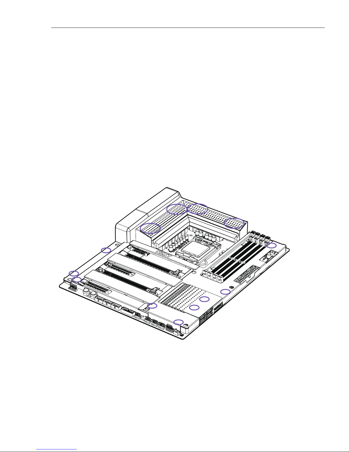
3.1 COVERS
Introduction
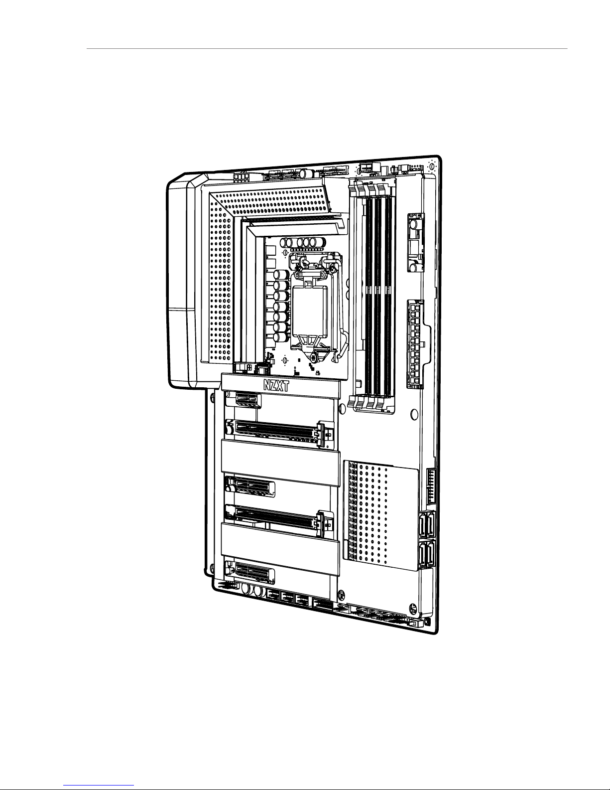
The cover pieces are latched onto the motherboard through multiple points. When
installing and removing, please pay close attention to these points and apply an
even force to prevent damage.
6
Page 11
Z370 ATX MOTHERBOARD
ENGLISH
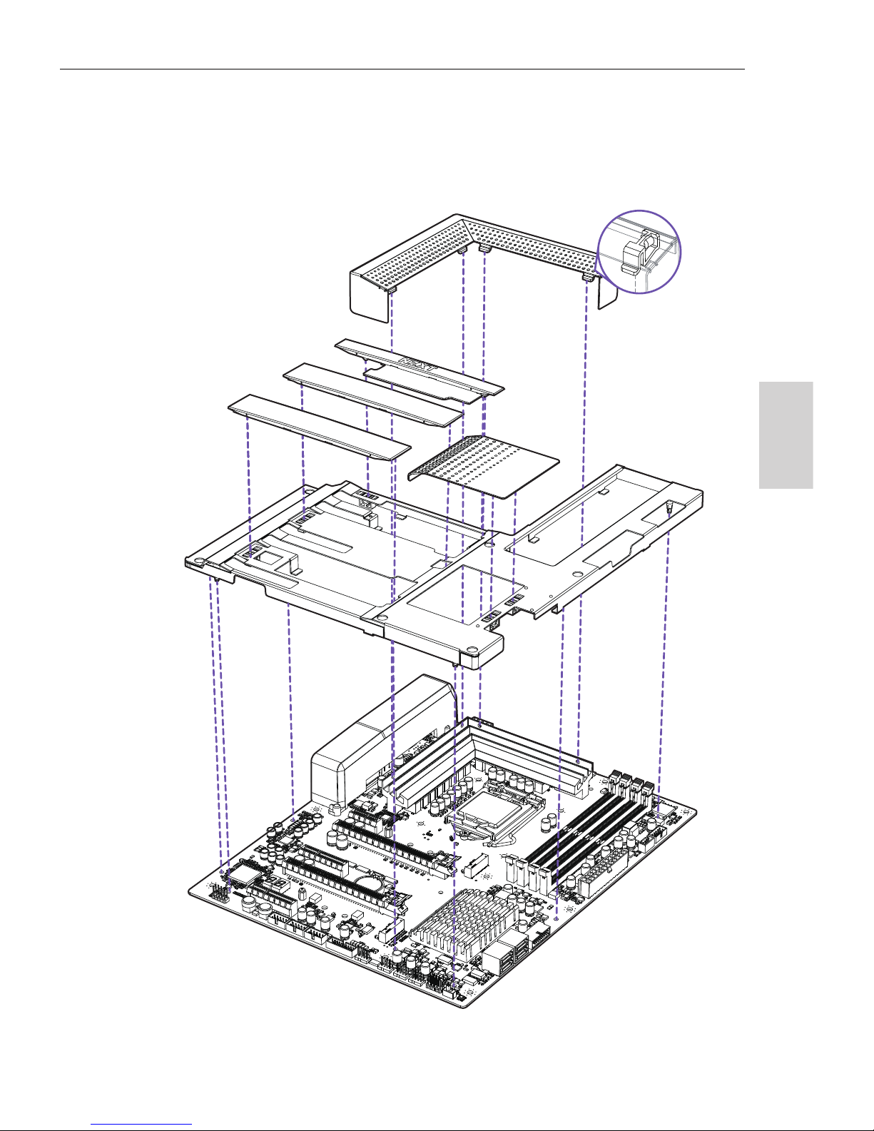
Exploded View
7
Page 12
N7
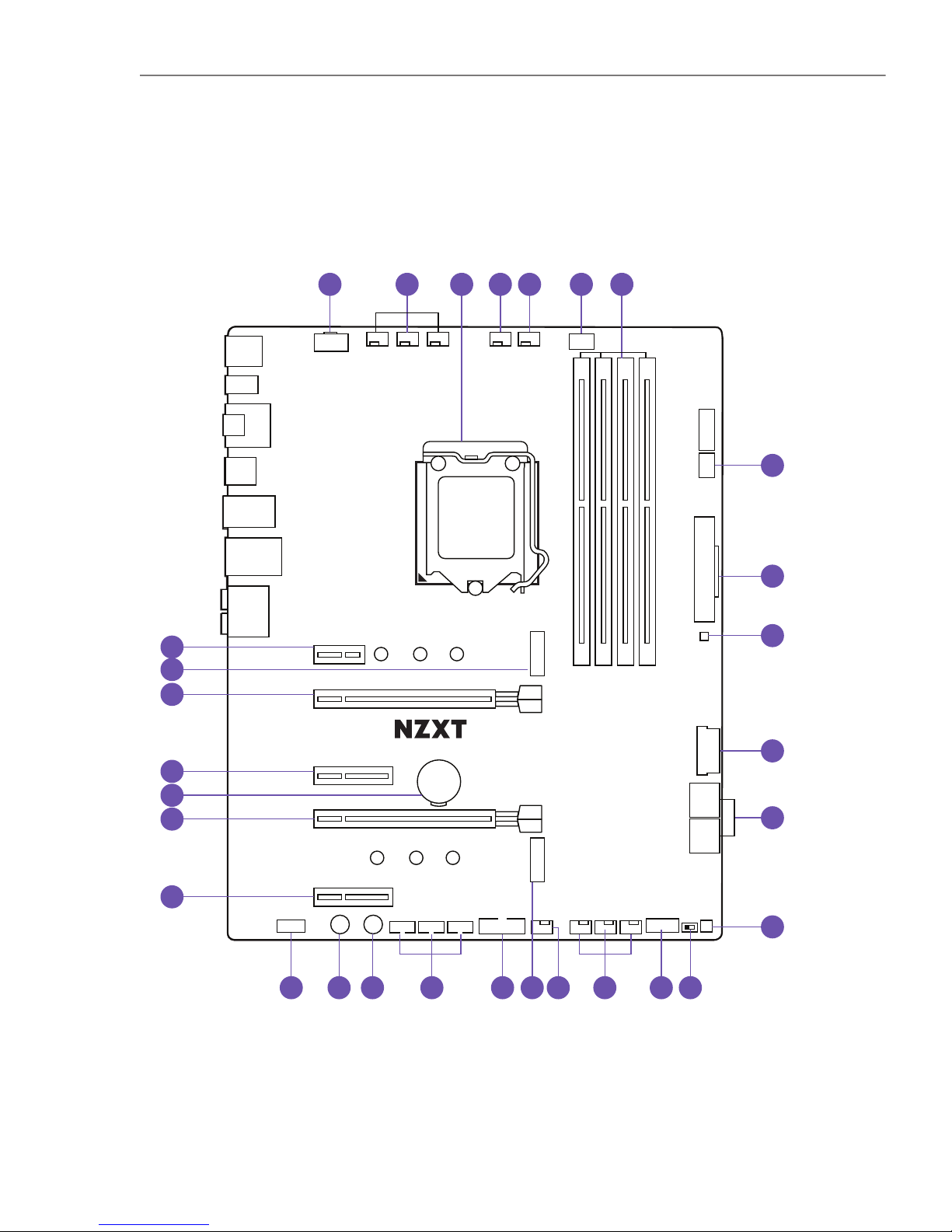
3.2 PORTS OVERVIEW
Designed in California
MODEL: N7-Z37XT
VERSION: 1.0
N7 Z370
LGA 1151
M2_2
PCIEX1_1
PCIEX16_1
PCIEX4_1
PCIEX16_2
PCIEX4_2
USB2_1
POWERRESET
USB2_2 USB2_3
USB3_1
SYS_FAN1W_PUMP SYS_FAN2 SYS_FAN3
F_PANEL
ROM_BACKUP
DUAL BIOS
USB3_2
CPU_FAN AIO_PUMPSYS_FAN6SYS_FAN5SYS_FAN4
ATX_12V
REAR_AUDIO
CLR_CMOS_BTN
HDMI_DP_SPDF
USB2_R
USB3_R
USB_LAN
KM_USB
SATA 3/4 SATA 1/2
ATX_POWER
LED1
LED2
A1 B1 A2 B2
M2_1
BATTERY
224222602280
224222602280
FRONT_AUDIO
5
6
7
9
10
11
22
23
24
25
26
27
28
8
4
2 31
30
1213141617 1518
19
2021
29
FIRST
8
Page 13
Z370 ATX MOTHERBOARD
ENGLISH
CPU Socket LGA 1151 socket for Intel 8th Generation processor
LED1 4-pin LED header
SATA 1-4 Serial ATA 6Gbps connectors
SYS_FAN 1-3
W_PUMP
4-pin fan connectors
4-pin connector for water pump
POWER Power button
PCIEX16_2 PCI Express x16 Gen3 slot for GPU
M2_1
M.2 Socket 3 with M key, supports type
2242/2260/2280 storage devices (Supports PCIE
mode)
CPU_FAN
AIO_PUMP
4-pin CPU fan connector
4-pin AIO pump connector
ATX_POWER 24-pin ATX power connector
ROM_BACKUP BIOS ROM backup button
M2_2
M.2 Socket 3 with M key, supports type
2242/2260/2280 storage devices (Supports
PCIE & SATA mode)
RESET Reset button
PCIEX1_1 PCI Express x1 Gen3 slot
LED2 4-pin LED header
Noise Detection Module Digital noise detection module for CAM
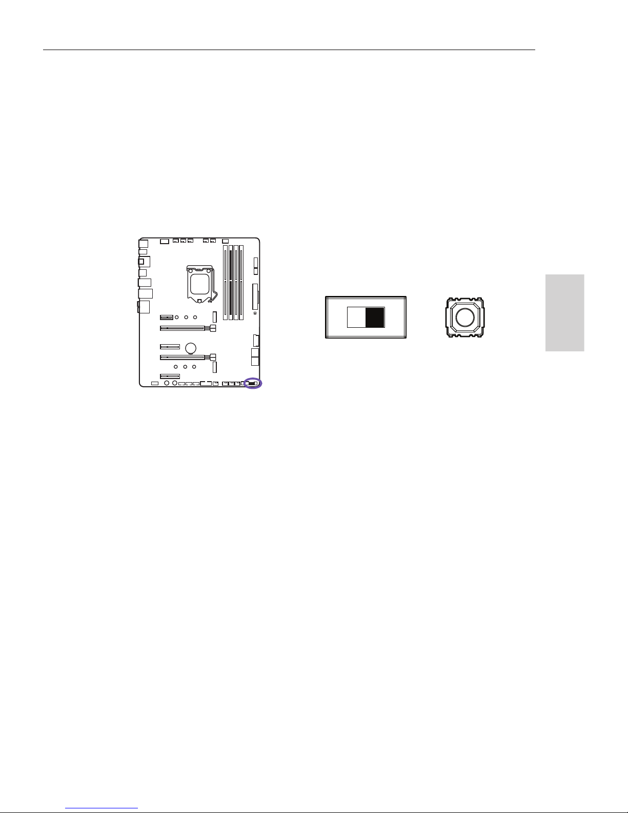
Dual BIOS Switch
Dual BIOS switch, toggle to the left for default
USB3_1 Front panel USB 3.1 Gen 1 header
FRONT_AUDIO Front panel audio connector
PCIEX4_1 PCI Express x4 Gen3 slot
ATX_12V 8-pin +12V power connector
DIMM A1-B2 288-pin DDR4 memory slots
USB3_2 Front panel USB 3.1 Gen 1 header
Front Panel Connectors Front panel switches and LED connectors
USB2_1-3 Front panel USB 2.0 headers
PCIEX4_2 PCI Express x4 Gen3 slot
Battery
PCIE16_1
Battery
PCI Express x16 Gen3 slot for GPU
SYS_FAN 4-6 4-pin fan connectors
1
5
9
13
17
21
25
2
6
10
14
18
22
3
7
11
15
19
23
27
29
4
8
12
16
20
24
26
28
30
No. Port Name Description
9
Page 14
N7
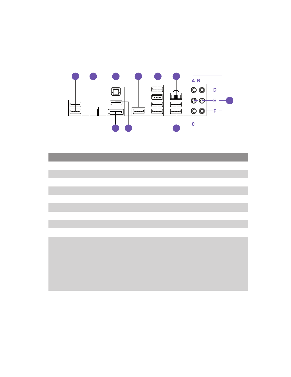
3.3 REAR I/O
USB 2.0 x 2
HDMI 1.4b port
USB 2.0 x 2
Clear CMOS button
USB 2.0 x 1
Audio Ports
A. Center and Subwoofer
B. Rear Surround
C. Side Surround
D. Line-in
E. Front Left and Right
F. Microphone
Optical SPDIF Out port
USB 3.1 Gen 1 x 4
DisplayPort port
RJ45 LAN port
1
5
9
2
6
10
3
7
4
8
No. Port Name
763
4 5 9
21 8
10
10
Page 15

Z370 ATX MOTHERBOARD
ENGLISH
11
Page 16
N7
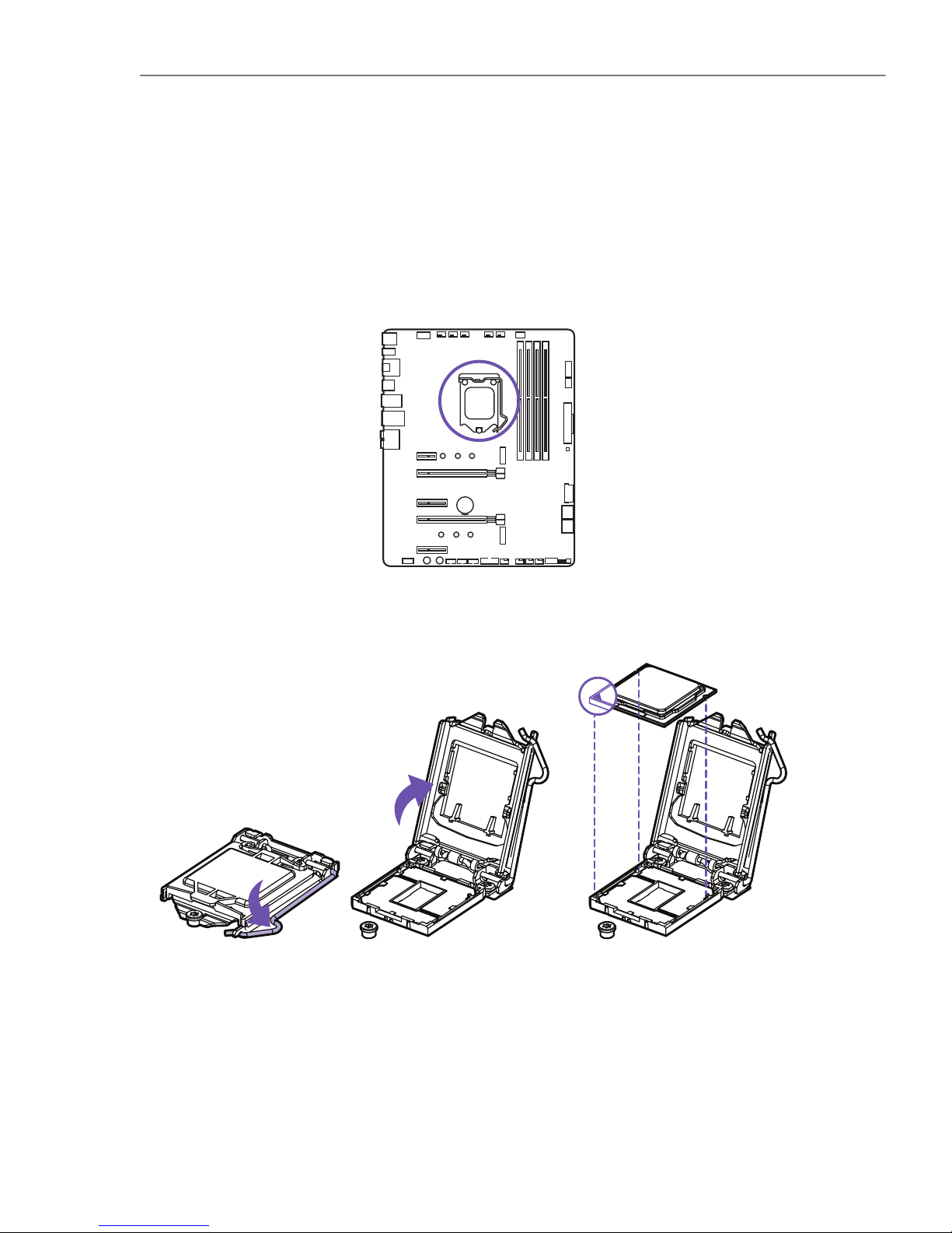
The surface of the LGA 1151 CPU has two notches and a golden triangle to assist in
correctly lining up the CPU for placement within the socket.
• Push down on the retention arm and outwards to release.
• Flip open the latch and place the CPU making sure the triangle and the notches on
the CPU matches the corner as indicated.
Installation
Introduction
3.4 CPU SOCKET
12
Page 17

Z370 ATX MOTHERBOARD
ENGLISH
• Close the latch and push down on the retention arm to lock it into place.
• The plastic protective cap will automatically become loosen.
• Apply thermal paste as needed and install your CPU cooler.
• Always unplug the power cord from the power outlet before installing or removing the CPU.
• Please retain the CPU protective cap after installing the CPU.
• Confirm that the CPU heatsink has been mounted properly before booting.
• Whenever the CPU is not installed, always protect the CPU socket pins by covering the socket with the plastic
protective cap.
• Please refer to the CPU cooler manufacturer’s instructions to install your cooler.
Note
13
Page 18

N7
The DIMM slots are located here. Please see the diagram for recommended memory
configuration.
• Push the release lever as indicated.
• Match the memory with the middle notch and align into the DIMM slots.
• Push the memory into the DIMM slot firmly until the level has been locked automatically.
Insert memory modules in the B1 slot first.
Note
Introduction
Installation
A1
B1
A2
B2
(Populate B1 First)
3.5 DIMM SLOTS
14
Page 19
Z370 ATX MOTHERBOARD
ENGLISH
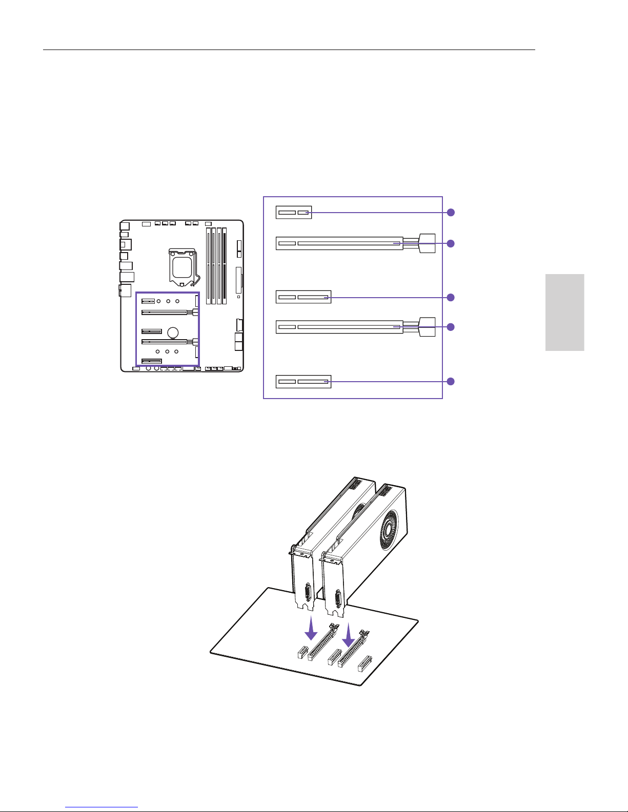
See the diagram below for the list of slots. Please install graphics cards using the
PCIEX16_1 first then the PCIEX16_2.
For power supply recommendations for SLI configurations, please refer to the user
guide of your graphics card to make sure you meet all the system requirements.
To install SLI graphics cards:
• Turn off your computer and disconnect the power cord, install two graphics cards
into the PCIEX16_1 and PCIEX16_2 slots.
Introduction
Multi-Graphic Cards Installation
PCIEX1_1:
PCIEX16_1:
PCIEX4_1:
PCIEX16_2:
PCIEX4_2
PCIe 3.0 x1 slot
PCIe 3.0 x16 slot
PCIe 3.0 x4 slot
PCIe 3.0 x8 slot
PCIe 3.0 x4 slot
3.6 PCI EXPRESS EXPANSION SLOTS
15
Page 20
N7
Note
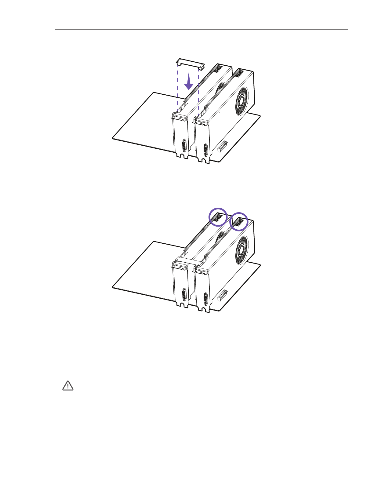
• For a single PCIe x16, please use PCIEX16_1.
• When adding or removing expansion cards, always turn off the power supply and unplug the power supply
power cable from the power outlet. Read the expansion card’s documentation to check for any necessary
additional hardware or software changes.
• Connect the two cards together using the SLI Bridge Connector.
• Connect all PCIe power connectors of the graphics cards.
• Reconnect the power cord, power up the computer and install the drivers and software included in your graphics card package.
16
Page 21
Z370 ATX MOTHERBOARD
ENGLISH
Note
• Please do not fold the SATA cable at a 90-degree angle. Data loss may result during transmission otherwise.
• SATA cables have identical plugs on either side of the cable. However, it is recommended that the flat connector be connected to the motherboard for space saving purposes.
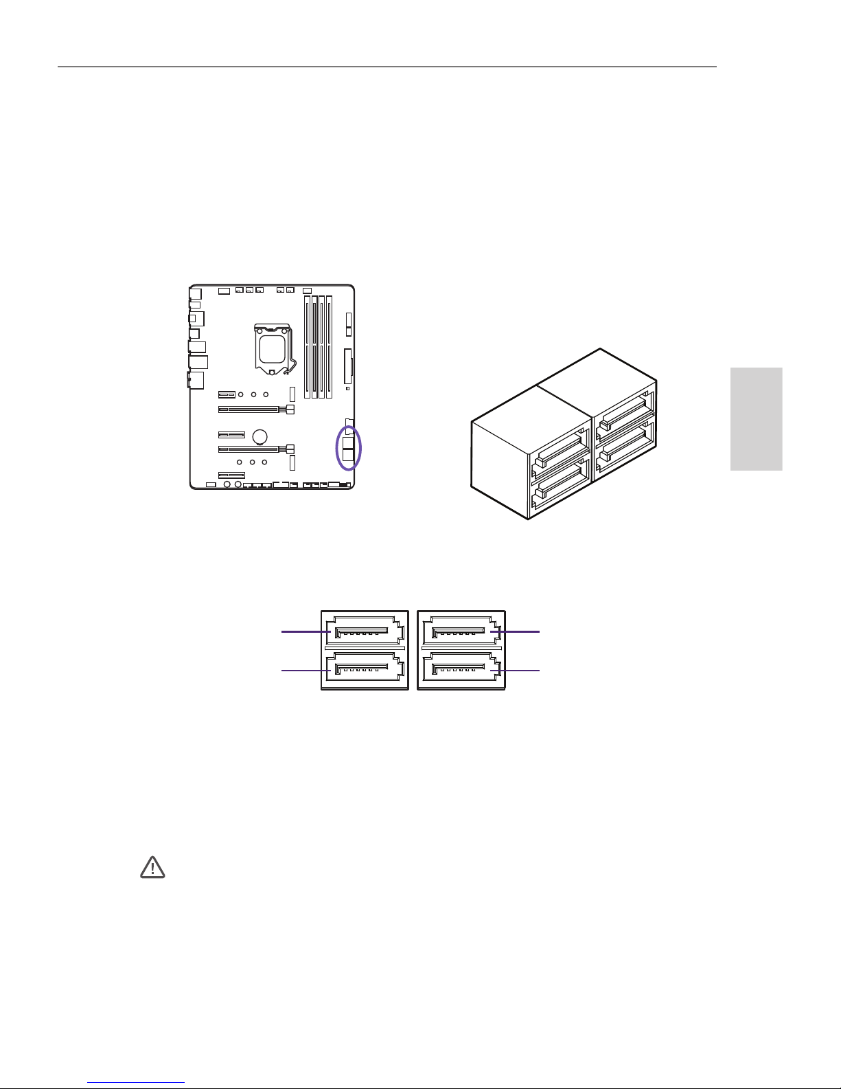
These connectors are SATA 6Gb/s interface ports. Each connector can connect to
one SATA device. No ports utilize the same bandwidth with any M.2.
Introduction
SATA 4
SATA 2
SATA 3
SATA 1
3.7 SATA CONNECTORS
17
Page 22
N7
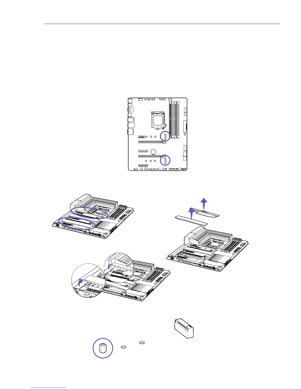
• Remove the M.2 slot cover.
• Confirm the standoff is at the required position and if necessary, move the standoff.
There are two M.2 slots on the N7 motherboard. You will need to remove the steel
cover pieces prior to installation. The M.2 slots supports form factors up to type
2280.
Introduction
Installation
1.
2.
3.
3.8 M.2 SLOTS
18
Page 23
Z370 ATX MOTHERBOARD
ENGLISH
Note
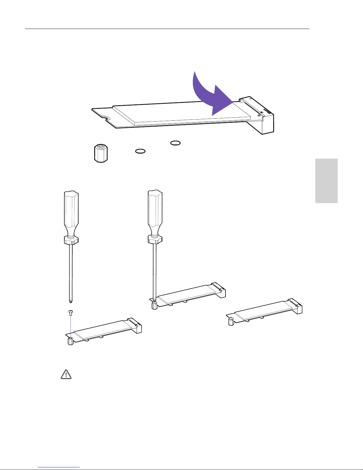
• Secure the M.2 drive using the M.2 screw onto the standoff and tighten.
• Insert your M.2 drive into the M.2 slot at an angle.
• If you have installed an M.2 drive, leave the steel cover off to ensure optimal cooling for your M.2 drives. The
NZXT logo cover piece has a removable M.2 cover, press on the lock and slide to release.
• Intel® RST only supports PCIe M.2 SSD with UEFI ROM.
• Intel® Optane™ Memory Ready for all M.2 slots.
19
Page 24
N7
Note
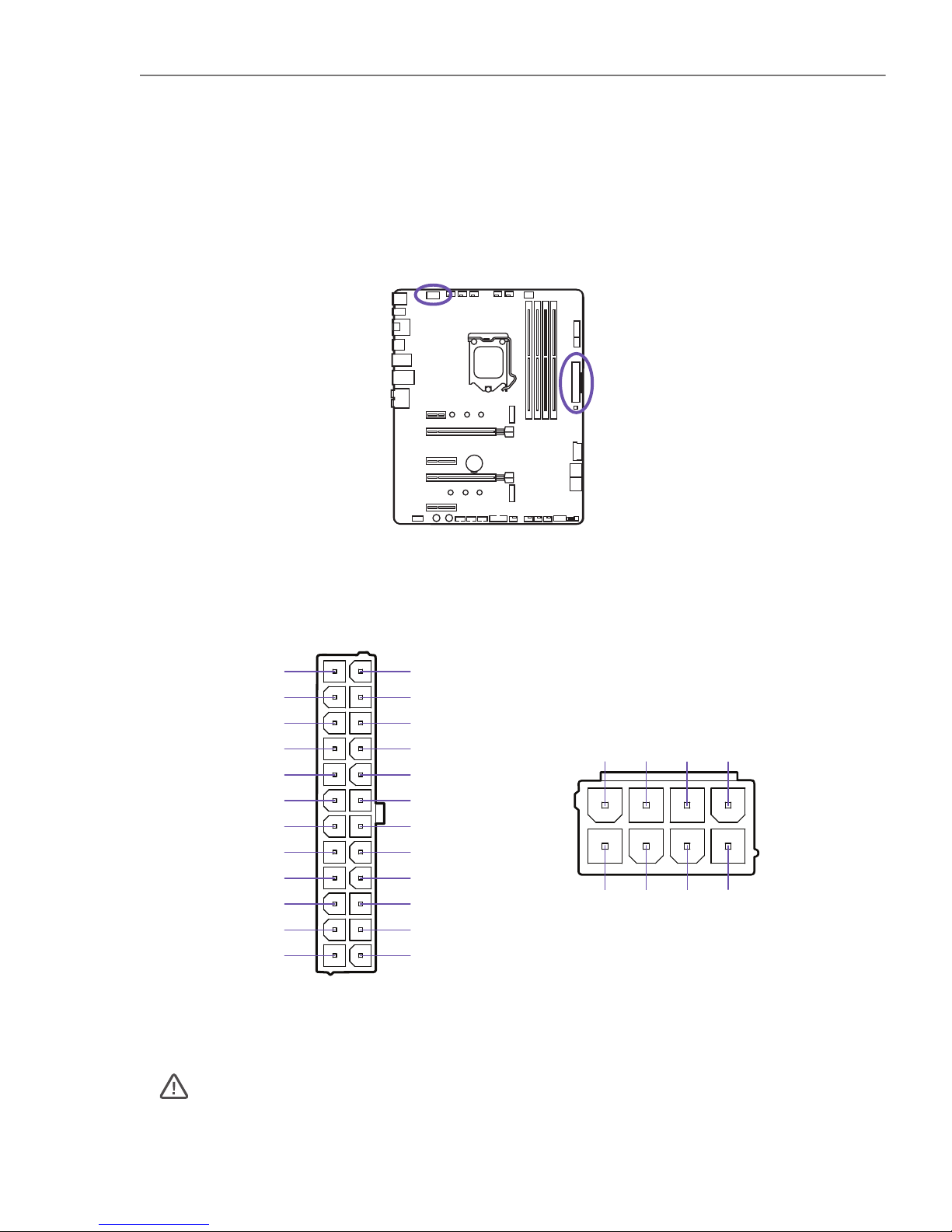
These connectors connect to an ATX power supply.
You may need to remove the mosfet cover piece before connecting the 8-pin CPU
power.
• Make sure that all the power cables are securely connected to a proper ATX power supply to ensure stable
operation of the motherboard.
8-pin ATX_12V
24-pin ATX_POWER
GND
+5V
+5V
+5V
RESERVED
GND
GND
GND
PSON#
GND
-12V
+3V
+3V
+12V
+12V
+5V STANDBY
POWER OK
GND
+5V
GND
+5V
GND
+3V
+3V
+12V DC
+12V DC
+12V DC
+12V DC
GND
GND
GND
GND
Introduction
3.9 POWER CONNECTORS
20
Page 25
Z370 ATX MOTHERBOARD
ENGLISH
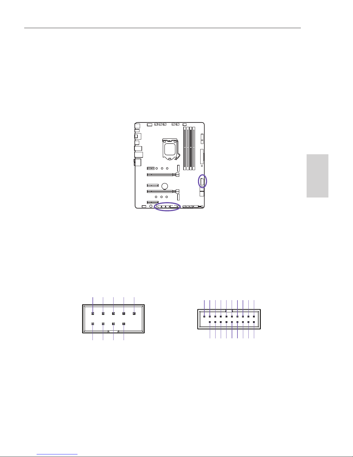
USB 3.0USB 2.0
These connectors allow you to connect to the front panel USB ports or devices requiring internal USB ports.
USB+5V
USB_P12-
USB_P12+
GND
NC
USB+5V
USB_P11+
GND
USB_P11-
POWER
USB3_RX_DN
USB3_RX_DP
GND
USB3_TX_C_DN
USB3_TX_C_DP
GND
USB2.0-
USB2.0+
GND
POWER
USB3_RX_DN
USB3_RX_DP
GND
USB3_TX_C_DN
USB3_TX_C_DP
GND
USB2.0-
USB2.0+
Introduction
3.10 USB 2.0 & 3.0 CONNECTORS
21
Page 26
N7
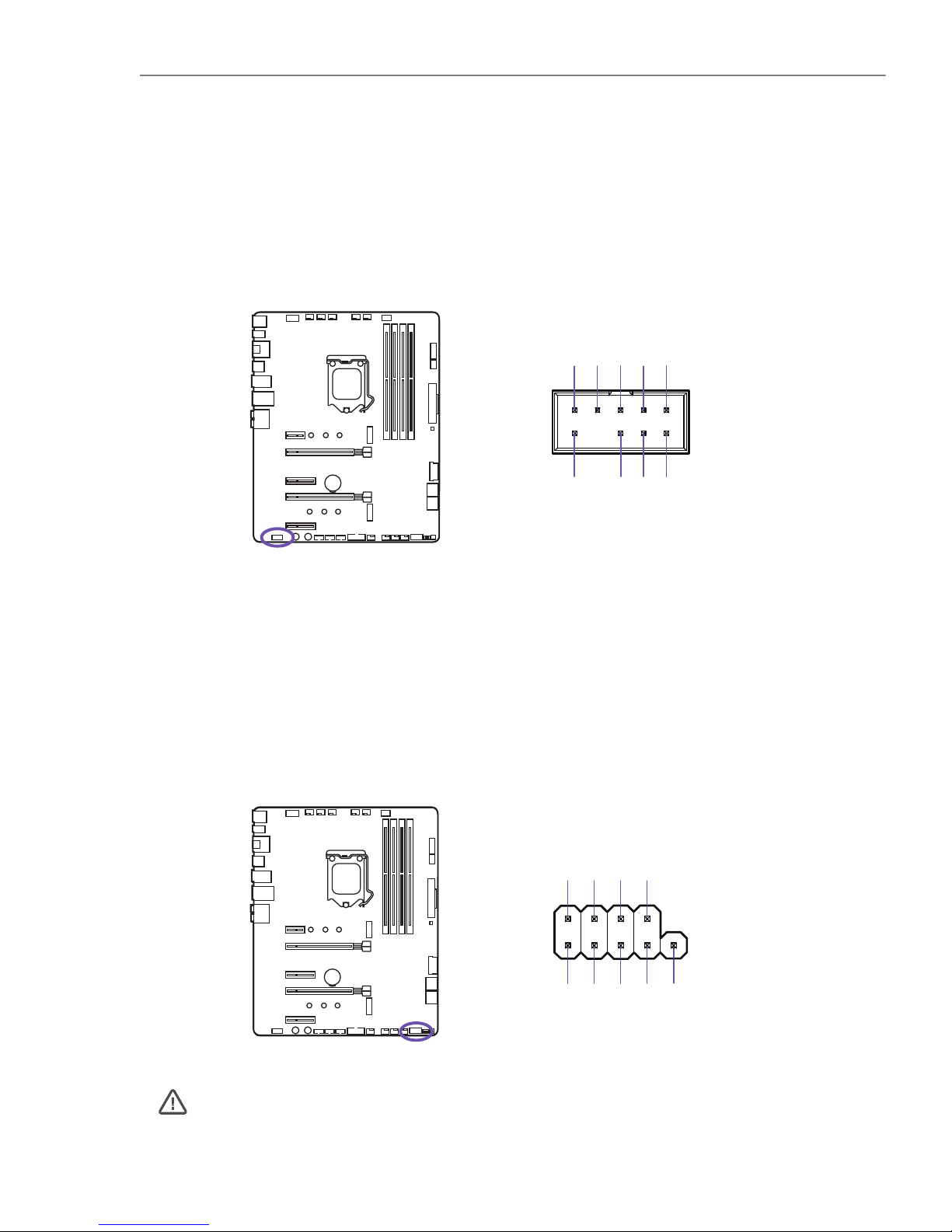
These connectors connect to the switches and indicator LEDs on the case.
Important
Please check the polarity of the pins to ensure your LEDs work properly.
This connector connects to the front panel audio on the case.
+HDD_LED
-RESET
+RESET
UNASSIGNED
-HDD_LED
+POWER_LED
+POWER_SW
-POWER_SW
-POWER_LED
FRONT L
SENSE_SEND
FRONT R
MIC R
MIC L
SENSE2_RETURN
SENSE1_RETURN
PRESENCE#
GND
Introduction
Introduction
3.11 FRONT PANEL AUDIO CONNECTOR
3.12 FRONT PANEL CONNECTOR
22
Page 27
Z370 ATX MOTHERBOARD
ENGLISH
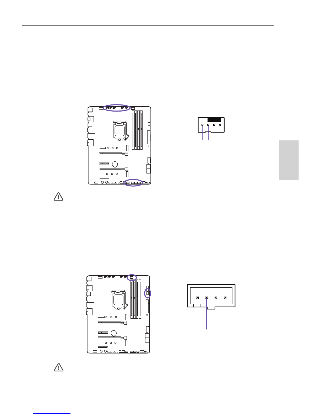
The CPU_FAN, AIO_PUMP, W_PUMP and the six SYS_FAN connectors support both
PWM(Pulse Width Modulation) and voltage modes. The fan speeds can be adjusted
within the BIOS or CAM.
Important
CAM is required to control the fans within Windows.
There are two LED ports located here and is used to attach to HUE+ LED strips or the
Aer RGB LED fans. Each port supports up to 4 LED strips or 5 Aer RGB fans.
Important
• Use the connection cable included in the HUE+ Extension Kit or Aer RGB.
• CAM is required to control the lighting within Windows.
5V
GND
DETECT
DATA IN
PWM
+12V
GND
SPEED SIGNAL
Introduction
Introduction
3.13 FAN CONNECTORS
3.14 LED CONNECTORS
23
Page 28
N7
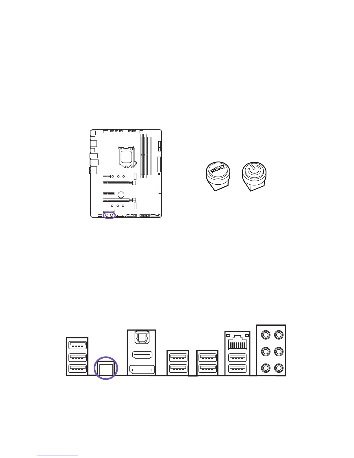
Clear CMOS Button
The power and reset button allows you to power on or reset the motherboard without connecting to a switch which is useful when testing.
The Clear CMOS button located on the rear I/O can be used to revert BIOS settings
to default. To clear CMOS, turn off the power and remove the AC power to the power supply. Allow 30 seconds to ensure no standby power exists. Press and hold the
Clear CMOS button for 3 seconds.
Introduction
3.15 BUTTONS & SWITCHES
24
Page 29
Z370 ATX MOTHERBOARD
ENGLISH
Dual BIOS Switch & ROM Back Up
BIOS Back Up
Located here is the “Dual BIOS switch” and “ROM_BACKUP” button. The N7 has two
built-in BIOS ROMs with the Primary set to A. If the Primary fails, you can switch to
B to load the Secondary BIOS ROM and revert the Primary BIOS back to factory (see
BIOS Back Up).
Turn off the power and remove the AC power to the power supply. Allow 30
seconds to ensure no standby power exists.
Flip the “Dual BIOS switch” to B and reconnect power to the power supply. The
ROM LED will glow indicating the Secondary BIOS has been loaded.
Boot into BIOS and navigate to Power Management under the Advanced Menu.
Disable EUP Function then proceed to save changes and reboot.
Power off the PC and press and hold the “ROM_BACKUP” button for 5 seconds.
The ROM LED will blink indicating it is currently loading the Secondary BIOS
ROM into the Primary BIOS ROM.
Back up is finished if the ROM LED remains on.
Turn off the power and remove the AC power to the PC. Allow 30 seconds to
ensure no standby power exists.
Flip the switch to side A to load the Primary BIOS.
When the Primary BIOS fails, perform the following steps to revert to the factory
BIOS.
•
•
•
•
•
•
•
•
B A
25
Page 30
N7
N7
Page 31

ESPAÑOL
Z370 ATX MOTHERBOARD
Z370 ATX MOTHERBOARD
CONTENIDO
1 PREFACIO.................................................................
2 INFORMACIÓN DEL PRODUCTO
2.1 Contenido del paquete......................................
2.2 Especificaciones.................................................
3 COMPONENTES Y PUERTOS
3.1 Cubiertas............................................................
3.2 Descripción general de los puertos......................
3.3 Interfaces de E/S traseras...................................
3.4 Zócalo de CPU....................................................
3.5 Ranuras DIMM....................................................
3.6 Ranuras de ampliación PCI Express......................
3.7 Conectores SATA.................................................
3.8 Ranuras M.2.......................................................
3.9 Conectores de alimentación................................
3.10 Conectores USB 2.0 y 3.0...................................
3.11 Conector de audio del panel frontal....................
3.12. Conector del panel frontal.................................
3.13. Conectores de ventilador...................................
3.14. Conectores de LED............................................
3.15. Botones e interruptores....................................
4 AVISOS SOBRE NORMATIVAS.....................................
5 SOPORTE Y SERVICIO................................................
6 AVISOS REGLAMENTARIOS........................................
7 INFORMACIÓN SOBRE LA BATERÍA.............................
8 DECLARACIÓN SOBRE WEEE.....................................
1
2
3
6
8
10
12
14
15
17
18
20
21
22
22
23
23
24
A-1
A-4
A-6
A-7
A-8
Page 32

N7
N7
Page 33

ESPAÑOL
Z370 ATX MOTHERBOARD
1. PREFACIO
A. Copyright © NZXT, Inc. Todos los derechos reservados.
Todo el contenido de este manual, incluidas las ilustraciones y capturas de
pantalla, está protegido por las leyes internacionales de copyright, con todos
los derechos reservados. Ni el presente manual ni el material que incluye podrá
reproducirse sin consentimiento por escrito del autor.
B. Renuncia de responsabilidad
La información de este documento está sujeta a cambios sin previo aviso. El
fabricante no realiza ninguna declaración o garantía con respecto a los contenidos del mismo y rechaza específicamente cualquier garantía implícita de
comerciabilidad o idoneidad para un fin particular. El fabricante se reserva el
derecho a revisar esta publicación y modificar el contenido cada cierto tiempo
sin obligación de notificar a nadie dichas revisiones o modificaciones.
C. Reconocimiento de marca comercial
Los nombres de productos utilizados en este manual son propiedad de sus
respectivos dueños y como tal se reconocen.
D. Precauciones de seguridad
Al instalar la placa base, sigue estas precauciones de seguridad:
Se recomienda llevar un brazalete antiestático conectado a un dispositivo de
toma de tierra para evitar daños causados por la electricidad estática.
Antes de empezar a trabajar en la placa base, toca la caja de metal de un objeto con conexión a tierra segura para descargar la electricidad estática.
Deja los componentes en bolsas antiestáticas.
Desenchufa siempre el cable de alimentación de la toma de corriente para
retirar la alimentación de CA antes de instalar o extraer la placa base u otros
componentes de hardware.
•
•
•
•
1
Page 34

N7
2. 2. INFORMACIÓN DEL PRODUCTO
2.1 CONTENIDO DEL PAQUETE
• Placa base N7 Z370
• Piezas de la cubierta N7
• Manual del usuario de la placa base
• Protector de E/S
• 4 cables SATA
• Conector de puente SLI
• 2 tiras de LED
• 2 cables de conexión de LED de 500 mm
• 2 cables de extensión de LED de 300 mm
2
Page 35

ESPAÑOL
Z370 ATX MOTHERBOARD
2.2 ESPECIFICACIONES
• Toma LGA 1151 para procesadores Intel® Core™ i7/i5/i3 de 8.ª generación
• Compatible con CPU Intel de 14 nm
• Compatible con la tecnología Intel Turbo Boost 2.0
Intel® Z370
4x DIMM, Max. 64GB, DDR4
Compatibilidad con salida Multi-VGA: Puertos HDMI/DisplayPort 1.2
Intel® Z370 Express Chipset
• Memoria 3866(O.C.)/ 3733(O.C.)/ 3600(O.C.)/ 3466(O.C.)/ 3400(O.C.)/ 3333(O.C.)/
3300(O.C.)/ 3200(O.C.)/ 3000(O.C.)/ 2800(O.C.)/ 2666(O.C.)/ 2400(O.C.)/ 2133 MHz no
ECC sin búfer
• Arquitectura de memoria de doble canal
• Compatibilidad con Intel® Extreme Memory Profile (XMP)
• DisplayPort con resolución máxima de 4096x2304 a 60 Hz
• HDMI™ con resolución máxima de 4096x2160 a 24 Hz
• Máximo de memoria compartida de 1024 MB
• 1 tipo M.2 2242/2260/2280 (PCIe 3.0 x4 y modo SATA)
• 1 tipo M.2 2242/2260/2280 (solo en modo PCIe 3.0 x4)
• 4 puertos SATA de 6 Gbps
• Compatible con tecnología NVIDIA® 2-Way SLI™
• Compatible con tecnología AMD 2-Way CrossFireX™
CPU y tomas
Chipset
Memoria
Compatibilidad con múltiples GPU
Gráficos integrados
Almacenamiento
Compatible con RAID 0/1/5/10
Compatible con tecnología Intel® Smart Response
Tecnología Intel® Rapid Storage
Preparada para memoria Intel® Optane
LAN
Intel® I219-V Gigabit
3
Page 36

N7
Audio
Ranuras de ampliación
Interfaces de E/S traseras
Sistema operativo
Diseño
Codificador Realtek® ALC1220
Audio de alta definición de 7.1 canales, 32 bits / DAC de 192 KHz
Microsoft® Windows® 10 de 64 bits
ATX
• 5 puertos USB 2.0
• 4 puertos USB 3.1 Gen 1
• 1 DisplayPort 1.2
• 1 HDMI™ 1.4b
• 1 botón de vaciado de CMOS
• 1 puerto LAN (RJ45)
• 1 puerto de salida óptica S/PDIF
• 1 toma de audio de 7.1 canales
• 2 PCIe 3.0 x16 (x16 o x8 doble)
• 2 PCIe 3.0 x4
• 1 PCIe 3.0 x1
4
Page 37

ESPAÑOL
Z370 ATX MOTHERBOARD
Interfaces de E/S internas
• 1 conector de alimentación EATX de 24 patillas
• 1 conector de alimentación ATX de 12 V y 8 patillas
• 1 conector CPU_FAN de 4 patillas
• 1 conector AIO_PUMP de 4 patillas
• 1 conector W_PUMP de 4 patillas
• 6 conectores SYS_FAN de 4 patillas
• 3 cabezales USB 2.0 (admiten hasta 6 puertos USB 2.0)
• 2 cabezales USB 3.1 Gen 1 (admiten hasta 4 puertos USB 3.1 Gen 1)
• 4 conectores SATA de 6 Gbps
• 1 toma M.2 de 3.ª generación con M Key, (PCIe 3.0 x4 y modo SATA)
• 1 toma M.2 de 3.ª generación con M Key, (solo modo PCIe 3.0 x4)
• 2 conectores de LED
• 1 módulo de detección de ruido
• 1 conector de audio de panel frontal
• 1 botón de encendido
• 1 botón de restablecimiento
• 1 botón de respaldo de ROM
• 1 interruptor de BIOS doble
5
Page 38

N7
3. COMPONENTES Y PUERTOS
3.1 CUBIERTAS
Introducción
Las piezas de la cubierta metálica N7 se pueden retirar manualmente. Están sujetas a la placa base mediante múltiples puntos. Al instalarlas y retirarlas, presta
especial atención a dichos puntos y aplica una fuerza uniforme para evitar daños.
6
Page 39

ESPAÑOL
Z370 ATX MOTHERBOARD
Vista detallada
7
Page 40

N7
3.2 DESCRIPCIÓN GENERAL DE LOS PUERTOS
Designed in California
MODEL: N7-Z37XT
VERSION: 1.0
N7 Z370
LGA 1151
M2_2
PCIEX1_1
PCIEX16_1
PCIEX4_1
PCIEX16_2
PCIEX4_2
USB2_1
POWERRESET
USB2_2 USB2_3
USB3_1
SYS_FAN1W_PUMP SYS_FAN2 SYS_FAN3
F_PANEL
ROM_BACKUP
DUAL BIOS
USB3_2
CPU_FAN AIO_PUMPSYS_FAN6SYS_FAN5SYS_FAN4
ATX_12V
REAR_AUDIO
CLR_CMOS_BTN
HDMI_DP_SPDF
USB2_R
USB3_R
USB_LAN
KM_USB
SATA 3/4 SATA 1/2
ATX_POWER
LED1
LED2
A1 B1 A2 B2
M2_1
BATTERY
224222602280
224222602280
FRONT_AUDIO
5
6
7
9
10
11
22
23
24
25
26
27
28
8
4
2 31
30
1213141617 1518
19
2021
29
FIRST
8
Page 41

ESPAÑOL
Z370 ATX MOTHERBOARD
Zócalo de CPU Zócalo LGA 1151 para procesador Intel de 8ª generación
LED1 Cabezal para LED de 4 patillas
SATA 1-4 Conectores Serial ATA de 6 Gbps
SYS_Fan 1-3
W_PUMP
Conectores para ventilador de 4 patillas
Conector de 4 patillas para bomba de agua
POWER Botón de encendido
PCIEX16_2 Ranura de PCI Express x16 de 3ª generación para GPU
M2_1
Toma M.2 de 3.ª generación con M Key, compatible con
dispositivos de almacenamiento tipo 2242/2260/2280
(compatible con modo PCIE)
CPU_FAN
AIO_PUMP
Conector para ventilador de la CPU de 4 patillas
Conector para bomba de AIO de 4 patillas
ATX_POWER Conector de alimentación ATX de 24 patillas
ROM_BACKUP Botón de respaldo de ROM de BIOS
M2_2
Toma M.2 de 3.ª generación con M Key, compatible con dispositivos de almacenamiento tipo
2242/2260/2280 (compatible con modo SATA y PCIE)
RESET Botón de restablecimiento
PCIEX1_1 Ranura de PCI Express x1 de 3ª generación
LED2 Cabezal para LED de 4 patillas
Módulo de detección de ruido Módulo digital de detección de ruido para CAM
Interruptor de BIOS doble
Interruptor de BIOS doble, hacia la izquierda para ajuste
predeterminado
USB3_1 Cabezal USB 3.1 Gen 1 del panel frontal
FRONT_AUDIO Conector de audio del panel frontal
PCIEX4_1 Ranura de PCI Express x4 de 3ª generación
ATX_12V Conector de alimentación de +12 V y 8 patillas
DIMM A1-B2 Ranuras para memoria DDR4 de 288 patillas
USB3_2 Cabezal USB 3.1 Gen 1 del panel frontal
Conectores del panel frontal
Conectores LED e interruptores del panel frontal
USB2_1-3 Cabezales USB 2.0 del panel frontal
PCIEX4_2 Ranura de PCI Express x4 de 3ª generación
Battery
PCIE16_1
Batería
Ranura de PCI Express x16 de 3ª generación para GPU
SYS_FAN 4-6 Conectores para ventilador de 4 patillas
1
5
9
13
17
21
25
2
6
10
14
18
22
3
7
11
15
19
23
27
29
4
8
12
16
20
24
26
28
30
No. Nombre del puerto Descripción
9
Page 42

N7
3.3 INTERFACES DE E/S TRASERAS
USB 2.0 x 2
Puerto HDMI 1.4b
USB 2.0 x 2
Botón de vaciado de CMOS
USB 2.0 x 1
Puertos de audio
A. Central y subwoofer
B. Envolvente trasero
C. Envolvente lateral
D. Entrada de línea
E. Frontal izquierdo y derecho
F. Micrófono
Puerto de salida SPDIF óptica
USB 3.1 Gen 1 x 4
Puerto DisplayPort
Puerto LAN RJ45
1
5
9
2
6
10
3
7
4
8
No.
763
4 5 9
21 8
10
Nombre del puerto
10
Page 43

ESPAÑOL
Z370 ATX MOTHERBOARD
11
Page 44

N7
La superficie de la CPU LGA 1151 tiene dos muescas y un triángulo dorado para ayudar a alinear la CPU correctamente al colocarla en el zócalo.
• Presiona hacia abajo y hacia afuera para soltar el brazo de retención.
• Abre el cierre y coloca la CPU asegurándote de que el triángulo y las muescas coinciden con la esquina, tal como se indica.
Instalación
Introducción
3.4 ZÓCALO DE CPU
12
Page 45

ESPAÑOL
Z370 ATX MOTHERBOARD
• Vuelve a cerrarlo y presiona hacia abajo el brazo de retención para fijarlo.
• La tapa protectora de plástico se aflojará automáticamente.
• Aplica pasta térmica según sea necesario e instala el refrigerador de CPU.
• Desenchufa siempre el cable de alimentación de la toma de corriente antes de instalar o extraer la CPU.
• Conserva la tapa protectora después de instalar la CPU.
• Confirma que el disipador térmico de la CPU se ha montado correctamente antes de arrancar.
• Cuando no esté instalada la CPU, cubre siempre el zócalo de la CPU con la tapa protectora para proteger las
patillas del zócalo.
• Consulta las instrucciones del fabricante del refrigerador de la CPU para instalarlo.
Nota
13
Page 46

N7
Las ranuras DIMM se encuentran aquí. Consulta el diagrama para ver la configuración de memoria recomendada.
• Presiona la palanca de desbloqueo tal y como se indica.
• Haz coincidir la memoria con la muesca intermedia y alinéala con las ranuras
DIMM.
• Introduce con firmeza la memoria en la ranura DIMM hasta que la palanca se bloquee automáticamente.
Inserta los módulos de memoria en la ranura B1 primero.
Nota
Introducción
Instalación
A1
B1
A2
B2
(Populate B1 First)
3.5 RANURAS DIMM
14
Page 47

ESPAÑOL
Z370 ATX MOTHERBOARD
Consulta el siguiente diagrama para ver la lista de ranuras. Instala las tarjetas gráficas utilizando en primer lugar la PCIEX16_1 y, en segundo lugar, la PCIEX16_2.
Para obtener recomendaciones de alimentación para configuraciones de SLI, consulta el manual del usuario de la tarjeta gráfica y asegúrate de que cumples todos
los requisitos del sistema.
Para instalar tarjetas gráficas SLI:
• Apaga el ordenador y desconecta el cable de alimentación, instala dos tarjetas
gráficas en las ranuras PCIEX16_1 y PCIEX16_2.
Introducción
Instalación de varias tarjetas gráficas
PCIEX1_1:
PCIEX16_1:
PCIEX4_1:
PCIEX16_2:
PCIEX4_2
PCIe 3.0 x1 slot
PCIe 3.0 x16 slot
PCIe 3.0 x4 slot
PCIe 3.0 x8 slot
PCIe 3.0 x4 slot
3.6 RANURAS DE AMPLIACIÓN PCI EXPRESS
15
Page 48

N7
Nota
• Para un único PCIe x16, utiliza PCIEX16_1.
• Al añadir o extraer tarjetas de expansión, desconecta siempre la fuente de alimentación y desenchufa el cable de alimentación de la toma de corriente. Lee la documentación de la tarjeta de expansión para comprobar
si se requieren cambios de software o hardware adicionales.
• Conecta las dos tarjetas mediante el conector de puente SLI.
• Conecta todos los conectores de alimentación PCIe de las tarjetas gráficas.
• Vuelve a conectar el cable de alimentación, enciende el ordenador e instala los
controladores y el software incluidos con las tarjetas gráficas.
16
Page 49

ESPAÑOL
Z370 ATX MOTHERBOARD
Nota
• Ten cuidado de no doblar el cable SATA en un ángulo de 90 grados. De hacerlo, puede dar lugar a una pérdida
de datos durante la transmisión.
• Los cables SATA tienen conectores idénticos a cada lado del cable. Sin embargo, se recomienda conectar el
conector plano a la placa base para ahorrar espacio.
Estos conectores son puertos de interfaz SATA de 6 Gb/s. Cada uno puede conectarse a un dispositivo SATA. Ningún puerto utiliza el mismo ancho de banda con
cualquier M.2.
Introducción
SATA 4
SATA 2
SATA 3
SATA 1
3.7 CONECTORES SATA
17
Page 50

N7
• Retira la cubierta de la ranura M.2.
• Asegúrate de que el separador se encuentra en la posición adecuada y muévelo si
es necesario.
Hay dos ranuras M.2 en la placa base N7. Tendrás que extraer las piezas de la cubierta de acero antes de la instalación. Las ranuras M.2 son compatibles con diseños
hasta el tipo 2280.
Introducción
Instalación
1.
2.
3.
3.8 RANURAS M.2
18
Page 51

ESPAÑOL
Z370 ATX MOTHERBOARD
Nota
• Fija la unidad M.2 con el tornillo M.2 en el separador y apriétalo.
• Inserta la unidad M.2 en la ranura M.2 en un ángulo.
• Si has instalado una unidad M.2, no vuelvas a colocar la cubierta de acero para garantizar una refrigeración
óptima de las unidades M.2. La cubierta del logotipo NZXT tiene una cubierta M.2 extraíble, presiona en el
bloqueo y desliza para soltarla.
• Intel® RST solo es compatible con SSD M.2 PCIe con ROM UEFI.
• Todas las ranuras M.2 preparadas para memoria Intel® Optane™.
19
Page 52

N7
Nota
Estos conectores se conectan a una fuente de alimentación ATX.
Es posible que tengas que retirar la cubierta del Mosfet antes de conectar la alimentación de CPU de 8 patillas.
• Asegúrate de que todos los cables de alimentación están bien conectados a una fuente de alimentación ATX
adecuada para garantizar el funcionamiento estable de la placa base.
ATX_12V de 8 patillas
ATX_POWER de 24 patillas
GND
+5V
+5V
+5V
RESERVED
GND
GND
GND
PSON#
GND
-12V
+3V
+3V
+12V
+12V
+5V STANDBY
POWER OK
GND
+5V
GND
+5V
GND
+3V
+3V
+12V DC
+12V DC
+12V DC
+12V DC
GND
GND
GND
GND
Introducción
3.9 CONECTORES DE ALIMENTACIÓN
20
Page 53

ESPAÑOL
Z370 ATX MOTHERBOARD
USB 3.0USB 2.0
Estos conectores te permiten conectar a los puertos USB del panel frontal o a dispositivos que requieran puertos USB internos.
USB+5V
USB_P12-
USB_P12+
GND
NC
USB+5V
USB_P11+
GND
USB_P11-
POWER
USB3_RX_DN
USB3_RX_DP
GND
USB3_TX_C_DN
USB3_TX_C_DP
GND
USB2.0-
USB2.0+
GND
POWER
USB3_RX_DN
USB3_RX_DP
GND
USB3_TX_C_DN
USB3_TX_C_DP
GND
USB2.0-
USB2.0+
Introducción
3.10 CONECTORES USB 2.0 Y 3.0
21
Page 54

N7
Estos conectores se conectan a los interruptores e indicadores LED de la caja.
Importante
Comprueba la polaridad de las patillas para asegurarte de que los LED funcionan correctamente.
Este conector se conecta al audio del panel frontal de la caja.
+HDD_LED
-RESET
+RESET
UNASSIGNED
-HDD_LED
+POWER_LED
+POWER_SW
-POWER_SW
-POWER_LED
FRONT L
SENSE_SEND
FRONT R
MIC R
MIC L
SENSE2_RETURN
SENSE1_RETURN
PRESENCE#
GND
Introducción
Introducción
3.11 CONECTOR DE AUDIO DEL PANEL FRONTAL
3.12 CONECTOR DEL PANEL FRONTAL
22
Page 55

ESPAÑOL
Z370 ATX MOTHERBOARD
El CPU_FAN, AIO_PUMP, W_PUMP y los seis conectores SYS_FAN son compatibles con
los modos de modulación de ancho de pulso (PWM, por sus siglas en inglés) y de tensión.
Las velocidades del ventilador se pueden ajustar en la BIOS o en CAM.
Nota
CAM se necesita para controlar los ventiladores dentro de Windows.
Hay dos puertos LED en este lugar que se utilizan para conectar con tiras LED HUE+
o ventiladores LED Aer RGB. Cada puerto admite hasta 4 tiras de LED o 5 ventiladores Aer RGB.
Nota
• Utiliza el cable de conexión incluido en el kit de extensión HUE+ o Aer RGB.
• CAM se necesita para controlar la iluminación dentro de Windows.
5V
GND
DETECT
DATA IN
PWM
+12V
GND
SPEED SIGNAL
Introducción
Introducción
3.13 CONECTORES DE VENTILADOR
3.14 CONECTORES DE LED
23
Page 56

N7
Botón de vaciado de CMOS
El botón de encendido y restablecimiento permite encender o restablecer la placa
base sin conectarse a un interruptor, lo cual resulta útil al hacer pruebas.
El botón de vaciado de CMOS situado en la interfaz de E/S trasera se puede utilizar
para volver a la configuración de BIOS predeterminada. Para el vaciado de CMOS,
apaga el equipo y retira la alimentación de CA. Espera 30 segundos para asegurarte
de que no queda alimentación de reserva. Mantén pulsado el botón de vaciado de
CMOS durante 3 segundos.
Introducción
3.15 BOTONES E INTERRUPTORES
24
Page 57

ESPAÑOL
Z370 ATX MOTHERBOARD
Interruptor de BIOS doble y respaldo de ROM
Copia de seguridad de la BIOS
Aquí se encuentran el “interruptor de BIOS doble” y el botón “ROM_BACKUP”. La N7
tiene integradas dos ROM de la BIOS, con el interruptor de la principal hacia el lado
A. Si la principal falla, puedes mover el interruptor al lado B para cargar la ROM de la
BIOS secundaria y restablecer la configuración original de la BIOS principal (consulta Copia de seguridad de la BIOS).
Apaga el equipo y retira la alimentación de CA de la fuente de alimentación. Espera 30 segundos para asegurarte de que no queda alimentación de reserva.
Mueve el “interruptor de BIOS doble” al lado B y vuelve a conectar la fuente de
alimentación. El LED de ROM se encenderá para indicar que se ha cargado la BIOS
secundaria.
Arranca la BIOS y ve a la sección de configuración de energía, en el menú de opciones avanzadas. Desactiva la función EUP, guarda los cambios y, a continuación,
reinicia el equipo.
Apaga el PC y mantén pulsado el botón “ROM_BACKUP” durante 5 segundos.
El LED de ROM parpadeará para indicar que se está cargando la ROM de la BIOS
secundaria en la ROM de la BIOS principal.
La copia de seguridad habrá terminado cuando el LED de ROM permanezca
encendido.
Apaga el equipo y retira la alimentación de CA del PC. Espera 30 segundos para
asegurarte de que no queda alimentación de reserva.
Mueve el interruptor al lado A para cargar la BIOS principal.
Si la BIOS principal falla, sigue los pasos que se indican a continuación para restablecer la configuración original de la BIOS.
•
•
•
•
•
•
•
•
B A
25
Page 58

N7
N7
Page 59

Z370 ATX MOTHERBOARD
FRANÇAIS
Z370 ATX MOTHERBOARD
TABLE DES MATIERES
1 PREFACE.................................................................
2 INFORMATIONS SUR LE PRODUIT
2.1 Contenu de l’emballage........................................
2.2 Spécifications.....................................................
3 COMPOSANTS ET PORTS
3.1 Caches................................................................
3.2 Présentation des ports........................................
3.3 E/S à l’arrière......................................................
3.4 Socket pour processeur.......................................
3.5 Slots DIMM........................................................
3.6 Slots d’expansion PCI Express.............................
3.7 Connecteurs SATA...............................................
3.8 Slots M.2...........................................................
3.9 Connecteurs d’alimentation.................................
3.10 Connecteurs USB 2.0 et 3.0................................
3.11 Connecteur audio pour panneau avant................
3.12. Connecteur panneau avant................................
3.13. Connecteurs de ventilateur................................
3.14. Connecteurs LED..............................................
3.15. Boutons et interrupteurs...................................
4 NOTICES REGLEMENTAIRES......................................
5 SOUTIEN ET SERVICE................................................
6 AVIS RÉGLEMENTAIRES.............................................
7 INFORMATION SUR LA BATTERIE................................
8 DÉCLARATION WEEE...............................................
1
2
3
6
8
10
12
14
15
17
18
20
21
22
22
23
23
24
A-1
A-4
A-6
A-7
A-8
Page 60

N7
N7
Page 61

Z370 ATX MOTHERBOARD
FRANÇAIS
1. PREFACE
A. Copyright© NZXT, Inc. Tous droits réservés.
Ce mode d’emploi, y compris toutes les illustrations et captures d’écran, est
protégé par les lois internationales sur la propriété intellectuelle, tous droits
réservés. Ce manuel et tous les documents qu’il contient ne peuvent pas être
reproduits sans le consentement écrit de l’auteur.
B.Renonciation
Les informations présentées dans ce document sont susceptibles d’être
modifiées sans avertissement. Le fabricant ne fait aucune déclaration et n’assure
aucune garantie relative au contenu de ce document et rejette spécifiquement
toute garantie implicite de qualité marchande ou de pertinence pour un usage
particulier. Le fabricant se réserve le droit de réviser cette publication et
d’apporter des modifications à son contenu de temps à autre, sans obligation de
sa part d’informer toute personne de cette révision ou de ces changements.
C. Reconnaissance de la marque
Les noms de produits utilisés dans ce mode d’emploi appartiennent à leurs
propriétaires respectifs et sont reconnus comme tels.
D. Précautions de sécurité
Respectez les précautions de sécurité suivantes lors de l’installation de la carte
mère:
Il est recommandé de porter un ruban de mise à la terre, attaché à un dispositif
mis à la terre pour éviter les dommages dus à l’électricité statique.
Avant de commencer à travailler sur la carte mère, déchargez votre électricité
statique en touchant le boîtier métallique d’un objet mis à la terre de manière
sécurisée.
Laissez les composants dans les sacs résistants à l’électricité statique.
Avant d’installer ou retirer la carte mère ou d’autres composants matériels,
retirez toujours le boîtier d’alimentation secteur en débranchant le câble de
la prise.
•
•
•
•
1
Page 62

N7
2. INFORMATIONS SUR LE PRODUIT
2.1 CONTENU DE L’EMBALLAGE
• Carte mère N7 Z370
• Caches N7
• Mode d’emploi de la carte mère
• Cache E/S
• 4 x câbles SATA
• Connecteur de montage en pont SLI
• 2 x bandes LED
• 2 x câbles de connexion LED de 500 mm
• 2 x câbles d’extension LED de 300 mm
2
Page 63

Z370 ATX MOTHERBOARD
FRANÇAIS
2.2 SPÉCIFICATIONS
• Socket LGA 1151 pour processeurs Intel® Core™ i7/i5/i3 de 8e génération
• Prise en charge de processeurs Intel de 14 nm
• Prise en charge de la technologie Intel Turbo Boost 2.0
Intel® Z370
4x DIMM, Max. 64Go, DDR4
Prise en charge de sortie multi-VGA : Ports HDMI/DisplayPort 1.2
Chipset Intel® Z370 Express
• 3866(O.C.)/ 3733(O.C.)/ 3600(O.C.)/ 3466(O.C.)/ 3400(O.C.)/ 3333(O.C.)/ 3300(O.C.)/
3200(O.C.)/ 3000(O.C.)/ 2800(O.C.)/ 2666(O.C.)/ 2400(O.C.)/ 2133 MHz pour mémoire
non-ECC et sans tampon
• Architecture de mémoire à double canal
• Prise en charge d’Intel® Extreme Memory Profile (XMP)
• DisplayPort avec résolution maxi de 4096x2304 à 60 Hz
• HDMI™ avec résolution maxi de 4096x2160 à 24 Hz
• Mémoire partagée maximale de 1024 Mo
• 1 x type M.22242/2260/2280 (mode PCIe 3.0 x4 et SATA)
• 1 x type M.2 2242/2260/2280 (mode PCIe 3.0 x4 uniquement)
• 4 x ports SATA 6 Gbit/s
• Prise en charge de la technologie NVIDIA® 2-Way SLI™
• Prise en charge de la technologie AMD 2-Way CrossFireX™
Processeur et socket
Puce
Mémoire
Prise en charge de plusieurs cartes graphiques
Ports graphiques
Stockage
Prise en charge de RAID 0/1/5/10
Prise en charge de la technologie Intel® Smart Response
Technologie Intel® Rapid Storage
Compatibilité mémoire Intel® Optane
LAN
LAN Intel® I219-V Gigabit
3
Page 64

N7
Audio
Slots d’expansion
E/S à l’arrière
Système d’exploitation
Format
Codec Realtek® ALC1220
Audio haute définition 7.1 canaux, 32 bits / 192 KHz DAC
Microsoft® Windows® 10 64-bit
ATX
• 5 x ports USB 2.0
• 4 x ports USB 3.1 Gen 1
• 1 x DisplayPort 1.2
• 1 x HDMI™ 1.4b
• 1 x bouton Clear CMOS
• 1 x port LAN (RJ45)
• 1 x port de sortie optique S/PDIF
• 1 x connecteur audio 7.1
• 2x PCIe 3.0 x16 (x16 ou double x8)
• 2x PCIe 3.0 x4
• 1x PCIe 3.0 x1
4
Page 65

Z370 ATX MOTHERBOARD
FRANÇAIS
• 1 x connecteur d’alimentation EATX à 24 broches
• 1 x connecteur d’alimentation ATX 12 V à 8 broches
• 1 x connecteur CPU_FAN à 4 broches
• 1 x connecteur AIO_PUMP à 4 broches
• 1 x connecteur W_PUMP à 4 broches
• 6 x connecteurs SYS_FAN à 4 broches
• 3 x têtes de bande USB 2.0 (prise en charge de 6 ports USB 2.0 maximum)
• 2 x têtes de bande USB 3.1 Gen 1 (prise en charge de 4 ports USB 3.1 Gen 1 maximum)
• 4 x connecteurs SATA 6 Gbit/s
• 1 x socket M.2 Gen3 avec M Key (mode PCIe 3.0 x4 et mode SATA)
• 1 x socket M.2 Gen3 avec M Key (mode PCIe 3.0 x4 uniquement)
• 2 x connecteurs LED
• 1 x module de détection de bruit
• 1 x connecteur audio pour panneau avant
• 1 x bouton d’alimentation
• 1 x bouton de réinitialisation
• 1 x bouton de sauvegarde ROM
• 1 x interrupteur double BIOS
E/S internes
5
Page 66

N7
3. COMPOSANTS ET PORTS
3.1 CACHES
Introduction
Entièrement métalliques, les caches N7 peuvent être retirés à la main. Ils se
clipsent sur la carte mère à plusieurs endroits. Lors de l’installation et du retrait,
faites attention à ces points d’attache et exercez une force égale pour éviter de les
endommager.
6
Page 67

Z370 ATX MOTHERBOARD
FRANÇAIS
Vue éclatée
7
Page 68

N7
3.2 PRÉSENTATION DES PORTS
Designed in California
MODEL: N7-Z37XT
VERSION: 1.0
N7 Z370
LGA 1151
M2_2
PCIEX1_1
PCIEX16_1
PCIEX4_1
PCIEX16_2
PCIEX4_2
USB2_1
POWERRESET
USB2_2 USB2_3
USB3_1
SYS_FAN1W_PUMP SYS_FAN2 SYS_FAN3
F_PANEL
ROM_BACKUP
DUAL BIOS
USB3_2
CPU_FAN AIO_PUMPSYS_FAN6SYS_FAN5SYS_FAN4
ATX_12V
REAR_AUDIO
CLR_CMOS_BTN
HDMI_DP_SPDF
USB2_R
USB3_R
USB_LAN
KM_USB
SATA 3/4 SATA 1/2
ATX_POWER
LED1
LED2
A1 B1 A2 B2
M2_1
BATTERY
224222602280
224222602280
FRONT_AUDIO
5
6
7
9
10
11
22
23
24
25
26
27
28
8
4
2 31
30
1213141617 1518
19
2021
29
FIRST
8
Page 69

Z370 ATX MOTHERBOARD
FRANÇAIS
Socket pour processeur
LED1
SATA 1-4
SYS_FAN 1-3
W_PUMP
POWER
PCIEX16_2
M2_1
CPU_FAN
AIO_PUMP
ATX_POWER
ROM_BACKUP
M2_2
RESET
PCIEX1_1
LED2
Module de détection
Interrupteur double
BIOS
USB3_1
FRONT_AUDIO
PCIEX4_1
ATX_12V
DIMM A1-B2
USB3_2
Connecteurs panneau
avant
USB2_1-3
PCIEX4_2
Battery
PCIE16_1
SYS_FAN 4-6
Socket LGA 1151 pour processeur Intel de 8e génération
Tête de bande LED à 4 broches
Connecteur Serial ATA 6 Gbit/s
Connecteurs de ventilateur à 4 broches
Connecteur à 4 broches pour la pompe à eau
Bouton d’alimentation
Slot PCI Express x16 Gen3 pour processeur graphique
Socket M.2 Gen3 avec M Key, prend en charge les dispositifs
de stockage de type 2242/2260/2280 (prend en charge les
modes PCIe)
Connecteur à 4 broches pour le ventilateur du processeur
Connecteur à 4 broches pour la pompe AIO
Connecteur d’alimentation ATX à 24 broches
Bouton de sauvegarde BIOS ROM
Socket M.2 Gen3 avec M Key, prend en charge les
dispositifs de stockage de type 2242/2260/2280
(prend en charge les modes PCIe et SATA)
Bouton de réinitialisation
Slot PCI Express x1 Gen3
Tête de bande LED à 4 broches
Module de détection de bruit numérique pour CAM
Interrupteur double BIOS, poussez-le vers la gauche pour le
mettre en position par défaut
Tête de bande USB 3.1 Gen 1 pour panneau avant
Connecteur audio pour panneau avant
Slot PCI Express x4 Gen3
Connecteur d’alimentation +12V à 8 broches
Slots pour carte mémoire DDR4 à 288 broches
Tête de bande USB 3.1 Gen 1 pour panneau avant
Interrupteurs et connecteurs LED du panneau avant
Têtes de bande USB 2.0 pour panneau avant
Slot PCI Express x4 Gen3
Battery
Slot PCI Express x16 Gen3 pour processeur graphique
Connecteurs de ventilateur à 4 broches
1
5
9
13
17
21
25
2
6
10
14
18
22
3
7
11
15
19
23
27
29
4
8
12
16
20
24
26
28
30
No. Nom description du port
9
Page 70

N7
3.3 E/S À L’ARRIÈRE
2 x USB 2.0
Port HDMI 1.4b
2 x USB 2.0
Bouton Clear CMOS
1 x USB 2.0
Ports audio
A. Central et caisson de basse
B. Surround arrière
C. Surround latéral
D. Line In
E. Avant gauche et droite
F. Microphone
Port de sortie optique SPDIF
4 x USB 3.1 Gen1
Port DisplayPort
Port LAN RJ45
1
5
9
2
6
10
3
7
4
8
No. Nom
763
4 5 9
21 8
10
10
Page 71

Z370 ATX MOTHERBOARD
FRANÇAIS
11
Page 72

N7
Le processeur LGA 1151 comporte deux encoches et un triangle doré pour aider à le
positionner correctement dans son socket.
• Appuyez sur le bras de fixation tout en le poussant vers l’extérieur pour l’ouvrir.
• Ouvrez le loquet et insérez le processeur en vous assurant que le triangle et les
encoches sur le CPU soient bien placés dans le coin comme indiqué.
Installation
Introduction
3.4 SOCKET POUR PROCESSEUR
12
Page 73

Z370 ATX MOTHERBOARD
FRANÇAIS
• Fermez le loquet et poussez le bras de fixation pour le remettre en place et le
verrouiller.
• Le capot de protection en plastique sera automatiquement déverrouillé.
• Appliquez de la pâte thermique et installez votre dissipateur pour processeur.
• Avant d’installer ou de retirer le processeur, débranchez toujours le câble d’alimentation de la prise électrique.
• Veuillez conserver le capot de protection du processeur après son installation.
• Assurez-vous que le dissipateur thermique du processeur est correctement installé avant de procéder à la
mise en marche.
• Lorsque le processeur est désinstallé, protégez toujours les broches du socket grâce en plaçant dessus le capot
de protection en plastique.
• Veuillez consulter les instructions du fabricant du dissipateur pour processeur avant de l’installer.
Remarque
13
Page 74

N7
Les slots DIMM sont situés ici. Consultez le diagramme pour découvrir la
configuration de mémoire recommandée.
• Poussez le levier d’ouverture comme indiqué.
• Faites correspondre la barrette de mémoire avec l’encoche du milieu et
alignez-la sur le slot DIMM.
• Poussez la barrette de mémoire fermement dans le slot DiMM jusqu’au verrouillage
automatique du levier.
Insérez d’abord les modules de mémoire dans le slot B1.
Remarque
Introduction
Installation
A1
B1
A2
B2
(Populate B1 First)
3.5 SLOTS DIMM
14
Page 75

Z370 ATX MOTHERBOARD
FRANÇAIS
Consultez le diagramme ci-dessous pour obtenir la liste des slots. Installez les
cartes graphiques d’abord dans le PCIEX16_1, puis dans le PCIEX16_2.
Pour obtenir les recommandations d’alimentation pour les configurations SLI,
consultez le mode d’emploi de votre carte graphique et vérifiez que votre système
correspond à la configuration requise.
Pour installer les cartes graphiques SLI :
• Éteignez votre ordinateur et débranchez le câble d’alimentation, installez deux
cartes graphiques dans les slots PCIEX16_1 et PCIEX16_2.
Introduction
Installation de plusieurs cartes graphiques
PCIEX1_1:
PCIEX16_1:
PCIEX4_1:
PCIEX16_2:
PCIEX4_2
PCIe 3.0 x1 slot
PCIe 3.0 x16 slot
PCIe 3.0 x4 slot
PCIe 3.0 x8 slot
PCIe 3.0 x4 slot
3.6 SLOTS D’EXPANSION PCI EXPRESS
15
Page 76

N7
Remarque
• Pour un PCIe x16 unique, utilisez le slot PCIEX16_1.
• Lors de l’ajout ou du retrait de cartes d’expansion, éteignez toujours l’alimentation et débranchez le câble
d’alimentation de la prise. Lisez la documentation relative à la carte d’expansion pour vérifier s’il est nécessaire d’effectuer des changements logiciels ou matériels supplémentaires.
• Reliez les deux cartes à l’aide du connecteur de montage en pont SLI.
• Reliez tous les connecteurs d’alimentation PCIe des cartes graphiques.
• Rebranchez le câble d’alimentation, allumez l’ordinateur et installez les pilotes et
logiciels inclus dans l’emballage de votre carte graphique.
16
Page 77

Z370 ATX MOTHERBOARD
FRANÇAIS
Remarque
• Ne pliez pas le câble SATA à 90 °. Cela pourrait engendrer une perte de données lors des transmissions.
• Les câbles SATA comportent des prises identiques à chaque extrémité. Néanmoins, il est recommandé de
brancher le connecteur plat sur la carte mère, dans une optique d’économie d’espace.
Ces connecteurs sont les ports d’interface SATA 6 Gbit/s. Chaque connecteur assure
la connexion à un seul dispositif SATA. Aucun port n’utilise la même bande passante
que les M.2.
Introduction
SATA 4
SATA 2
SATA 3
SATA 1
3.7 CONNECTEURS SATA
17
Page 78

N7
• Retirez le cache du slot M.2.
• Assurez-vous que l’entretoise est en position requise. Si nécessaire, déplacez-la.
La carte mère N7 comporte deux slots M.2. Il vous faudra retirer les caches en acier
avant l’installation. Les slots M.2 prennent en charge les facteurs de forme jusqu’au
type 2280.
Introduction
Installation
1.
2.
3.
3.8 SLOTS M.2
18
Page 79

Z370 ATX MOTHERBOARD
FRANÇAIS
Remarque
• Sécurisez le lecteur M.2 sur l’entretoise à l’aide de la vis M.2 et serrez.
• Insérez votre lecteur M.2 en biais dans le slot M.2.
• Si vous avez installé un lecteur M.2, ne replacez pas le cache en acier afin d’assurer un refroidissement
optimal pour vos lecteurs M.2. Le cache avec le logo NZXT comporte un cache M.2 amovible. Appuyez sur le
verrou et faites-le glisser pour libérer le cache.
• Intel® RST prend en charge uniquement les SSD PCIe M.2 avec UEFI ROM.
• Tous les slots M.2 sont compatibles Intel® Optane™ Memory.
19
Page 80

N7
Remarque
Ces connecteurs assurent la connexion à une alimentation ATX.
Il vous faudra peut-être retirer le cache du MOSFET avant de connecter
l’alimentation du CPU à 8 broches.
• Afin d’assurer la stabilité du fonctionnement de la carte mère, vérifiez que tous les câbles d’alimentation sont
correctement branchés à une alimentation ATX adaptée.
ATX_12V à 8 broches
ATX_POWER à 24 broches
GND
+5V
+5V
+5V
RESERVED
GND
GND
GND
PSON#
GND
-12V
+3V
+3V
+12V
+12V
+5V STANDBY
POWER OK
GND
+5V
GND
+5V
GND
+3V
+3V
+12V DC
+12V DC
+12V DC
+12V DC
GND
GND
GND
GND
Introduction
3.9 CONNECTEURS D’ALIMENTATION
20
Page 81

Z370 ATX MOTHERBOARD
FRANÇAIS
USB 3.0USB 2.0
Ces connecteurs vous permettent d’assurer la connexion avec les ports du panneau
avant ou les dispositifs nécessitant des ports USB internes.
USB+5V
USB_P12-
USB_P12+
GND
NC
USB+5V
USB_P11+
GND
USB_P11-
POWER
USB3_RX_DN
USB3_RX_DP
GND
USB3_TX_C_DN
USB3_TX_C_DP
GND
USB2.0-
USB2.0+
GND
POWER
USB3_RX_DN
USB3_RX_DP
GND
USB3_TX_C_DN
USB3_TX_C_DP
GND
USB2.0-
USB2.0+
Introduction
3.10 CONNECTEURS USB 2.0 ET 3.0
21
Page 82

N7
Ces connecteurs assurent la connexion avec les interrupteurs et les voyants LED
situés sur le boîtier.
Important
Vérifiez la polarité des broches pour assurer le bon fonctionnement des voyants LED.
Ce connecteur assure la connexion avec le port audio du panneau avant situé sur
le boîtier.
+HDD_LED
-RESET
+RESET
UNASSIGNED
-HDD_LED
+POWER_LED
+POWER_SW
-POWER_SW
-POWER_LED
FRONT L
SENSE_SEND
FRONT R
MIC R
MIC L
SENSE2_RETURN
SENSE1_RETURN
PRESENCE#
GND
Introduction
Introduction
3.11 CONNECTEUR AUDIO POUR PANNEAU AVANT
3.12 CONNECTEUR PANNEAU AVANT
22
Page 83

Z370 ATX MOTHERBOARD
FRANÇAIS
Le connecteur CPU_FAN, AIO_PUMP, W_PUMP et les 6 connecteurs SYS_FAN prennent en charge à la fois le mode MLI (modulation de largeur d’impulsion) et le mode
tension. La vitesse du ventilateur peut être modifiée dans le BIOS ou via CAM.
Remarque
CAM est nécessaire pour contrôler les ventilateurs depuis Windows.
Deux ports LED sont situés ici et assurent la connexion avec les bandes LED HUE+
ou les ventilateurs LED Aer RGB. Chaque port prend en charge jusqu’à 4 bandes LED
ou 5 ventilateurs Aer RGB.
Remarque
• Utilisez le câble de connexion inclus dans le kit d’extension HUE+ ou Aer RGB.
• CAM est nécessaire pour contrôler l’éclairage depuis Windows.
5V
GND
DETECT
DATA IN
PWM
+12V
GND
Introduction
Introduction
3.13 CONNECTEURS DE VENTILATEUR
3.14 CONNECTEURS LED
23
Page 84

N7
Bouton Clear CMOS
Les boutons d’alimentation et de réinitialisation vous permettent d’allumer ou
de réinitialiser la carte mère sans avoir à la brancher à un interrupteur. Cela peut
s’avérer utile lors de tests.
Le bouton Clear CMOS situé sur l’E/S à l’arrière peut être utilisé pour remettre les
paramètres BIOS à leur configuration par défaut. Pour effacer CMOS, éteignez la
carte mère et débranchez l’alimentation CA. Attendez 30 secondes pour être sûr qu’il
n’y ait pas de système de veille. Appuyez sur le bouton Clear CMOS et maintenez-le
enfoncé pendant 3 secondes.
Introduction
3.15 BOUTONS ET INTERRUPTEURS
24
Page 85

Z370 ATX MOTHERBOARD
FRANÇAIS
Interrupteur double BIOS et sauvegarde ROM
Sauvegarde BIOS
L’interrupteur « Dual BIOS » et le bouton « ROM_BACKUP » sont situés ici. La carte
mère N7 comporte deux ROM BIOS intégrés. L’ensemble principal est l’ensemble
A. Si l’ensemble principal tombe en panne, vous pouvez passer à B pour charger le
ROM BIOS secondaire et repasser le BIOS principal à saconfiguration d’usine (voir
Sauvegarde BIOS).
Éteignez et débranchez l’alimentation CA. Attendez 30 secondes pour être sûr
qu’il n’y ait pas de système de veille.
Faites glisser « l’interrupteur double BIOS » en position B et rebranchez
l’alimentation. Le LED ROM s’éclairera pour indiquer que le BIOS secondaire a été
chargé.
Démarrez dans le BIOS et rendez-vous à Power Management (Gestion de l’alimentation) dans le menu Advanced (Avancé). Désactivez la fonction EUP et enregistrez les modifications avant de redémarrer.
Éteignez l’ordinateur et appuyez sur le bouton « ROM_BACKUP » pendant 5
secondes.
Le LED ROM clignotera pour indiquer qu’il est en train de charger le ROM BIOS
secondaire dans le ROM BIOS principal.
La sauvegarde est terminée lorsque le LED ROM cesse de clignoter.
Éteignez et débranchez l’alimentation secteur de l’ordinateur. Attendez 30 secondes pour être sûr qu’il n’y ait pas de système de veille.
Faites glisser l’interrupteur en position A pour charger le BIOS primaire.
Lorsque le BIOS principal tombe en panne, effectuez les étapes suivantes pour le
repasser à sa configuration d’usine.
•
•
•
•
•
•
•
•
B A
25
Page 86

N7
Page 87

DEUTSCH
Z370 ATX MOTHERBOARD
INHALT
1 VORWORT.................................................................
2 PRODUKTINFORMATIONEN
2.1 Lieferumfang......................................................
2.2 Technische Daten...............................................
3 KOMPONENTEN UND ANSCHLÜSSE
3.1 Abdeckungen......................................................
3.2 Anschlussübersicht............................................
3.3 E/A Rückseite.....................................................
3.4 CPU-Sockel........................................................
3.5 DIMM-Steckplätze..............................................
3.6 PCI Express-Erweiterungssteckplätze..................
3.7 SATA-Anschlüsse.................................................
3.8 M.2-Steckplätze.................................................
3.9 Stromanschlüsse................................................
3.10 USB 2.0- und 3.0-Anschlüsse.............................
3.11 Audioanschluss an der Vorderseite.....................
3.12. Anschluss an der Vorderseite............................
3.13. Lüfteranschlüsse..............................................
3.14. LED-Anschlüsse...............................................
3.15. Tasten und Schalter..........................................
4 REGULATORISCHE HINWEISE....................................
5 UNTERSTÜTZUNG UND SERVICE................................
6 RECHTSVORSCHRIFTEN............................................
7 BATTERIEINFORMATIONEN........................................
8 WEEE DIE ERKLÄRUNG..............................................
1
2
3
6
8
10
12
14
15
17
18
20
21
22
22
23
23
24
A-1
A-4
A-6
A-7
A-8
Page 88

N7
Page 89

Z370 ATX MOTHERBOARD
DEUTSCH
1. VORWORT
A. Copyright© NZXT, Inc. Alle Rechte vorbehalten.
Dieses Handbuch einschließlich aller Illustrationen und Screenshots ist durch internationale Urheberrechtsgesetze geschützt. Alle Rechte vorbehalten. Jegliche
Vervielfältigung dieses Handbuchs oder seiner Inhalte bedarf der schriftlichen
Genehmigung durch den Verfasser.
B. Haftungsausschluss
Angaben im vorliegenden Dokument können ohne Vorankündigung geändert
werden. Der Hersteller erteilt keine Zusicherungen oder Garantien in Bezug auf
diese Inhalte und lehnt insbesondere jegliche stillschweigenden Gewährleistungen
der Marktgängigkeit oder der Eignung für einen bestimmten Zweck ausdrücklich
ab. Der Hersteller behält sich das Recht vor, diese Veröffentlichung zu bearbeiten
und nach eigenem Ermessen zu ändern, wobei der Hersteller nicht verpflichtet
ist, Mitteilungen zu derartigen Überarbeitungen oder Änderungen zu machen.
C. Marken
In diesem Handbuch verwendete Produktnamen sind Eigentum der jeweiligen Inhaber und werden ausdrücklich als solches anerkannt.
D. Sicherheitsvorkehrungen
Beachten Sie die folgenden Sicherheitsvorkehrungen bei der Installation des
Mainboards:
Zum Schutz vor Schäden durch elektrostatische Entladung wird die Verwendung eines Antistatikbands empfohlen, das an ein geerdetes Gerät angeschlossen ist.
Entladen Sie statische Elektrizität, indem Sie das Metallgehäuse eines sicher
geerdeten Objekts berühren, bevor Sie mit dem Mainboard arbeiten.
Bewahren Sie Komponenten stets in den antistatischen Beuteln auf.
Trennen Sie stets die Stromversorgung, bevor Sie das Mainboad oder andere
Hardwarekomponenten installieren oder entfernen. Ziehen Sie dazu den Netzstecker aus der Steckdose.
•
•
•
•
1
Page 90

N7
2. PRODUKTINFORMATIONEN
2.1 LIEFERUMFANG
• N7 Z370 Mainboard
• N7 Abdeckungen
• Mainboard Benutzerhandbuch
• E/A-Abdeckung
• 4x SATA-Kabel
• SLI-Bridge-Anschluss
• 2x LED-Streifen
• 2x 500 mm LED-Verbindungskabel
• 2x 300 mm LED-Verlängerungskabel
2
Page 91

Z370 ATX MOTHERBOARD
DEUTSCH
2.2 TECHNISCHE DATEN
• LGA-Sockel 1151 für Intel® Core™ der 8. Generation – i7/i5/i3-Prozessoren
• Unterstützt Intel 14 nm CPU
• Unterstützt Intel® Turbo Boost Technologie 2.0
Intel® Z370
4x DIMM, Max. 64 GB, DDR4
Unterstützung von Multi-VGA-Ausgabe: HDMI/DisplayPort 1.2-Anschlüsse
Intel® Z370 Express Chipsatz
• 3866 (Übertaktung)/ 3733 (Übertaktung)/ 3600 (Übertaktung)/ 3466 (Übertaktung)/
3400 (Übertaktung)/ 3333 (Übertaktung)/ 3300 (Übertaktung)/ 3200 (Übertaktung)/
3000 (Übertaktung)/ 2800 (Übertaktung)/ 2666 (Übertaktung)/ 2400 (Übertaktung)/
2.133 MHz Non-ECC, ungepufferter Speicher
• Zweikanal-Speicherarchitektur
• Unterstützt Intel® Extreme Memory Profile (XMP)
• DisplayPort mit max. Auflösung von 4.096 x 2.304 bei 60 Hz
• HDMI® mit max. Auflösung von 4.096 x 2.160 bei 24 Hz
• Maximaler gemeinsam genutzter Speicher 1.024 MB
• 1x M.2 Typ 2242/2260/2280 (PCIe 3.0 x4- und SATA-Modus)
• 1x M.2 Typ 2242/2260/2280 (nur PCIe 3.0 x4-Modus)
• 4x SATA-Anschlüsse 6 Gb/s
• Unterstützt NVIDIA® 2-Way SLI™-Technologie
• Unterstützt AMD 2-Way CrossFireX™-Technologie
CPU und Sockel
Chipsatz
Speicher
Multi-GPU-Unterstützung
Integrated Graphics
Speicher
Unterstützt RAID 0/1/5/10
Unterstützt Intel® Smart Response-Technologie
Intel® Rapid-Storage-Technologie
Intel® Optane Memory Ready
LAN
Intel® I219-V Gigabit LAN
3
Page 92

N7
Audio
Erweiterungssteckplätze
E/A Rückseite
Betriebssystem
Formfaktor
Realtek® ALC1220 Soundkarte
7.1-Kanal High Definition Audio, 32 Bit/192 KHz DAC
Microsoft® Windows® 10 64-bit
ATX
• 5x USB 2.0-Anschlüsse
• 4x USB 3.1 Gen 1-Anschlüsse
• 1x DisplayPort 1.2
• 1x HDMI 1.4b
• 1x Clear CMOS-Schalter
• 1x LAN (RJ45)-Anschluss
• 1x Optischer S/PDIF-Out-Anschluss
• 1x 7.1-Kanal Audio-Buchsen
• 2x PCIe 3.0 x16 (x16 oder 2 x8)
• 2x PCIe 3.0 x4
• 1x PCIe 3.0 x1
4
Page 93

Z370 ATX MOTHERBOARD
DEUTSCH
E/A intern
• 1x 24-poliger EATX-Stromanschluss
• 1x 8-poliger ATX12V-Stromanschluss
• 1x 4-poliger Anschluss CPU_FAN
• 1x 4-poliger Anschluss AIO_PUMP
• 1x 4-poliger Anschluss W_PUMP
• 6x 4-polige Anschlüsse SYS_FAN
• 3x USB 2.0 Header (Unterstützung von bis zu 6 USB 2.0-Anschlüssen)
• 2x USB 3.1 Gen 1 Header (Unterstützung von bis zu 4 USB 3.1 Gen 1-Anschlüssen)
• 4x SATA-Anschlüsse 6 Gb/s
• 1x M.2 Sockel 3 mit Taste M, (PCIe 3.0 x4- und SATA-Modus)
• 1x M.2 Sockel 3 mit Taste M (nur PCIe 3.0 x4-Modus)
• 2x LED-Anschlüsse
• 1x Geräuscherkennungsmodul
• 1x Audioanschluss an der Vorderseite
• 1x Netzschalter
• 1x Reset-Taste
• 1x ROM-Backup Taste
• 1x Dual BIOS-Schalter
5
Page 94

N7
3. KOMPONENTEN UND ANSCHLÜSSE
3.1 ABDECKUNGEN
Einführung
Die Metallabdeckungen des N7 können manuell entfernt werden. Sie sind an
mehreren Stellen am Mainboard arretiert. Achten Sie beim Installieren und
Entfernen bitte sorgfältig auf diese Stellen und wenden Sie eine gleichmäßige
Krafteinwirkung an, um Schäden zu verhindern.
6
Page 95

Z370 ATX MOTHERBOARD
DEUTSCH
Explosionszeichnung
7
Page 96

N7
3.2 ANSCHLUSSÜBERSICHT
Designed in California
MODEL: N7-Z37XT
VERSION: 1.0
N7 Z370
LGA 1151
M2_2
PCIEX1_1
PCIEX16_1
PCIEX4_1
PCIEX16_2
PCIEX4_2
USB2_1
POWERRESET
USB2_2 USB2_3
USB3_1
SYS_FAN1W_PUMP SYS_FAN2 SYS_FAN3
F_PANEL
ROM_BACKUP
DUAL BIOS
USB3_2
CPU_FAN AIO_PUMPSYS_FAN6SYS_FAN5SYS_FAN4
ATX_12V
REAR_AUDIO
CLR_CMOS_BTN
HDMI_DP_SPDF
USB2_R
USB3_R
USB_LAN
KM_USB
SATA 3/4 SATA 1/2
ATX_POWER
LED1
LED2
A1 B1 A2 B2
M2_1
BATTERY
224222602280
224222602280
FRONT_AUDIO
5
6
7
9
10
11
22
23
24
25
26
27
28
8
4
2 31
30
1213141617 1518
19
2021
29
FIRST
8
Page 97

Z370 ATX MOTHERBOARD
DEUTSCH
CPU-Sockel LGA 1151 Sockel für Intel-Prozessor der 8. Generation
LED1 4-poliger LED-Header
SATA 1–4 Serielle SATA-Anschlüsse 6 Gb/s
SYS_FAN 1–3
W_PUMP
4-polige Lüfteranschlüsse
4-poliger Anschluss für Wasserpumpe
POWER Netzschalter
PCIEX16_2 PCI-Express x16 Gen3-Steckplatz für GPU
M2_1
M.2 Sockel 3 mit Taste M, unterstützt
Speichergeräte der Typen 2242/2260/2280
(Unterstützt PCIE-Modus)
CPU_FAN
AIO_PUMP
4-poliger CPU-Lüfteranschluss
4-poliger AIO-Pumpenanschluss
ATX_POWER 24-poliger ATX-Stromanschluss
ROM_BACKUP BIOS ROM-Backup Taste
M2_2
M.2 Sockel 3 mit Taste M, unterstützt
Speichergeräte der Typen 2242/2260/2280
(Unterstützt PCIE- und SATA-Modus)
RESET Reset-Taste
PCIEX1_1 PCI-Express x1 Gen3-Steckplatz
LED2 4-poliger LED-Header
Geräuscherkennungsmodul Digitales Geräuscherkennungsmodul für CAM
Dual BIOS-Schalter
Dual-BIOS-Schalter, für Standardeinstellung nach links schalten
USB3_1 FUSB 3.1 Gen 1-Header an der Vorderseite
FRONT_AUDIO Audioanschluss an der Vorderseite
PCIEX4_1 PCI-Express x4 Gen3-Steckplatz
ATX_12V 8-poliger 12V-Stromanschluss
DIMM A1-B2 288-Pin DDR4-Steckplätze
USB3_2 USB 3.1 Gen 1-Header an der Vorderseite
Anschlüsse an der Vorderseite Schalter und LED-Anschlüsse an der Vorderseite
USB2_1-3 USB 2.0-Header an der Vorderseite
PCIEX4_2 PCI-Express x4 Gen3-Steckplatz
Battery
PCIEX16_1
Batterie
PCI-Express x16 Gen3-Steckplatz für GPU
SYS_FAN 4-6 4-polige Lüfteranschlüsse
1
5
9
13
17
21
25
2
6
10
14
18
22
3
7
11
15
19
23
27
29
4
8
12
16
20
24
26
28
30
Nr. Port Name Beschreibung
9
Page 98

N7
3.3 E/A RÜCKSEITE
USB 2.0 x 2
HDMI 1.4b-Anschluss
USB 2.0 x 2
CMOS-Schalter
USB 2.0 x 1
Audio-Anschlüsse
A. Center und Subwoofer
B. hinterer Surround-Sound
C. seitlicher Surround-Sound
D. Eingang
E. Vorne links und rechts
F. Mikrofon
Optischer S/PDIF-Out-Anschluss
USB 3.1 Gen 1 x 4
DisplayPort-Anschluss
RJ45-LAN-Anschluss
1
5
9
2
6
10
3
7
4
8
Nr. Port Name
763
4 5 9
21 8
10
10
Page 99

Z370 ATX MOTHERBOARD
DEUTSCH
11
Page 100

N7
Zwei Kerben und das goldene Dreieck an der Oberfläche der LGA 1151 CPU erleichtern
die korrekte Ausrichtung und Platzierung im Sockel.
• Drücken Sie die Halterung nach unten und außen, um sie zu öffnen
• Öffnen Sie die Arretierung und positionieren Sie die CPU so, dass das Dreieck und
die Kerben wie abgebildet an den Ecken ausgerichtet sind.
nstallation
Einführung in die LGA 1151 CPU
3.4 CPU-SOCKEL
12
 Loading...