

Page 1
TEMPEST
User’s manual
Page 2

Page 3

NZXT. 1
Thank you.
Dear valued customers,
Thank you for purchasing our product. We are thankful to all our
fans for the continuing support, after just four years since entering the
computer chassis market with the Guardian in 2003, NZXT is now an
established gaming brand and manufacturer of quality hardware in the
market today. Since then, we have stayed true to our goal, which was to
continuously provide innovative next generation products. With every
product, we are still breaking more boundari es and limits. Once again, thank
you and all NZXT fans for the supp ort and we hope to bring more amazing
products in the coming years.
After you complete your installation, please come by our community forums
at www.nzxt.com/forum
and voice your opinions with thousands of NZXT
fans from around the world
Sincerely,
NZXT Team
Page 4

NZXT. 2
Tempest Specifications
Features
> Airflow King: Dual 120mm intake, dual 140mm exhaust with an additional
side 120mm fan and rear 120mm fan all included.
> Maximize Expandability: E-ATX support allows more compatibility with
high end components including large graphic cards.
> Easier accessibility & cable management: Cable routing is pre-drilled
on the motherboard so users can hide cables behind the motherboard tray,
allowing more a cleaning look and better airflow. Power, E-SAT A, USB and
Reset buttons are mounted at the top to give better accessibility.
> Bottom mounted PSU: PSU mounting at the bottom allows for more
security and separation of heat from the CPU.
> Server-like HDD space: Dual 120mm fans cool cages that hold up to 8
HDDs allowing for large capacity systems while maintainin g cool
temperatures.
Detailed specifications
Dimension: W211.5 *H521.5 *D562mm
Form factor: E-ATX Support, ATX, M-ATX Support
7 Expansion slots
3 x External 5.25” Bays (up to 6 x 5.25”)
8 x Internal HDD bays
1 x External 3.5”Brackets
Cooling Options:
2 x 120 mm Blue LED Intakes (Included)
2 x 140 mm Black Top Exhausts (Included)
1 x 120mm Rear Exhaust (Included)
1 x 120mm Intake Side (Included)
Page 5

NZXT. 3
Table of Contents
Thank you. ..................................................................................... 1
Tempest Specifications .................................................................. 2
Before Beginning.. ......................................................................... 4
Getting starting............................................................................... 4
Motherboard Installation ................................................................ 5
LED, Power and Reset Installation ................................................ 5
External 5.25” Drive Bay Installation ............................................. 7
External 3.5” Drive Bay Installation................................................ 9
Internal 3.5” Drive Bay Installation ............................................... 11
Front fan, filters and HDD Cage usage ....................................... 13
Installing the power supply .......................................................... 14
Managing the cables .................................................................... 15
Being water cooling ready ........................................................... 15
Support and Service .................................................................... 17
Page 6
NZXT. 4
Before Beginning..
For safety issues, it is highly recommended that all users wear
gloves during installation. Also, if you have any questions during
installation, please send an email to service@nzxt.com
before
proceeding. Thank you.
Getting starting
For users building a new system, it is recommended that the side
panels are removed before beginning the installation. The following
steps will outline the steps to remove the top, side panels and the
motherboard tray.
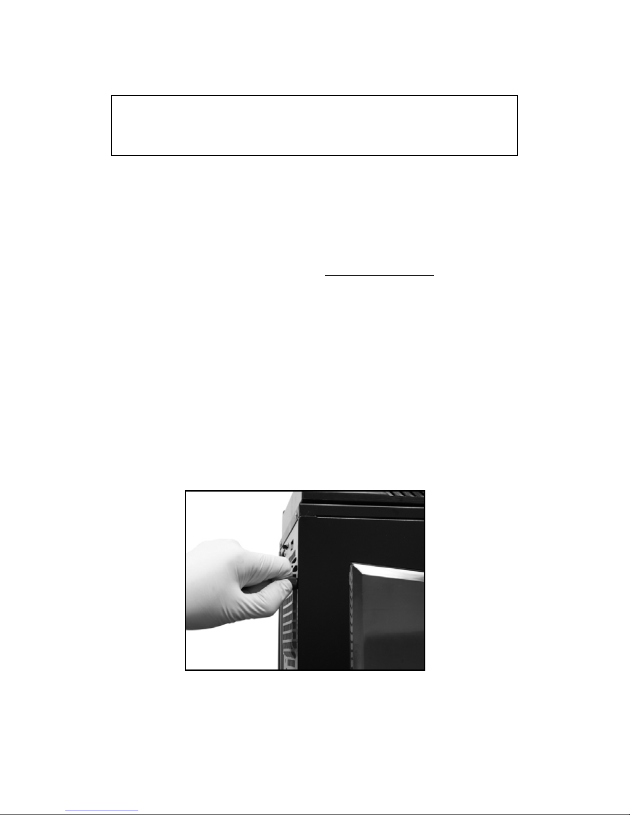
1. Remove the thumb screws securing the side panels.
2. Pull the side panel back, and then lift the panel to remove it.
Opening the side panel
NOTE: CPU, RAM and any peripheral installation are not
included in this manual. Please refer to your motherboard manual
for related mountin
g
instructions and troubleshooting.
Page 7

NZXT. 5
Motherboard Installation
Please refer to the case interior infrastructure and secure the powe r
supply at the back of the case by using the screws provided.
1. Match the motherboard form factor ( ATX, M-ATX, MiniATX ) with the holes on the motherboard tray
2. Secure the standoffs onto the holes which match your
motherboard
3. Lay the motherboard onto the standoffs and then
continue to secure the motherboard with the screws
provided.
LED, Power and Reset Installation
Please refer first to your motherboard manual to locate where the
power switch and reset pins are located. The power and reset
buttons are located at the top of the chassis. The colors following
each instruction designate the color of the wires.
USB, Audio ports, E-SATA, Reset, and Power buttons
1. Connect the reset switch (labeled RESET SW) by
connecting to your motherboard RESET connector. Make
sure you always attach the white wire to ground. (Blue/White
+/-)
Page 8

NZXT. 6
2. Connect the power switch pin (labeled POWER SW) to the
PWR connector on the motherboard. (Yellow/White +/-)
3. Connect the HDD LED (labeled H.D.D LED) to the
appropriate headers on your motherboard. The HDD LED
located on the front panel should flash green when there is
activity in the hard drive. (Green/White, +/-)
4. Connect the four pin molex leading from the front panel to
activate that two blue LED stripes.
HDD LED location
All White and Black Pin Connectors correspond to
ground.
USB Installation
1. The USB is located of the top on your front panel.
2. Refer to your motherboard manual and match the labels on
the USB port connectors with your motherboard in order to
install.
Page 9

NZXT. 7
Audio Port Installation
1. Please first refer to your motherboard manual and match the
labels on the audio wires with your motherboard pins.
2. The green input is the speaker input and the pink input is the
microphone input.
Case Pins Signal Description ASUS© Pins
MIC-IN Front Microphone input Signal MIC2
MIC-POWER Front Microphone Power MICPWR
GROUND Front Audio Ground AGND
L-OUT Front Left Channel Audio Signal Line out_L
R-OUT Front Right Channel Audio Signal Line out_R
L-RET Rear Left Channel Audio Signal
BLINE Line
out_L
R-RET Rear Right Channel Audio Signal
BLINE Line
out_R
ASUS© Motherboard Pin Assignment
External 5.25” Drive Bay Installation [Bays 1-3]
Please follow the directions below to install the 5.25” in the top 3
bays of the Tempest:
1. Remove the front panel of the chassis by pulling from the
opening at the bottom of the front panel.
Page 10

NZXT. 8
2. Remove the 5.25” black mesh for the 5.25” bay, by pushing
the clips aside from inside the panel or unscrewin g the
screw (3 bays are screwed onto the panel)
3. Reattach the front panel.
4. Slide the 5.25” drive in from the front of the chassis.
Insert the 5.25” Device throug h the opening
5. Match the holes with the bay and the screw less bracket
Attach the screw less bracket matching the 5.25” holes
Page 11

NZXT. 9
6. Turn the screw less bracket to lock the drive.
Turn and lock the device in place. User may choose to screw the
device on also.
External 5.25” Drive Bay Installation [Bays 4-6]
Please follow the directions below to install the 5.25” in bays 4 to 6 of
the Tempest:
1. Remove the front panel of the chassis by pulling at the
bottom of the front panel.
2. Remove the screws securing the bay.
Page 12

NZXT. 10
3. Remove the cage.(Refer to page 13 for more information)
4. Attach the rails to the side of the case.
5. Slide the 5.25” drive into the rail position until a click sound
is heard
6. Reattach the front panel.
Page 13

NZXT. 11
External 3.5” Drive Bay Installation
The NZXT Tempest comes standard with one external 5.25” to 3.5”
bracket attached to the inside the 3
rd
bay. Please follow the
directions below to install the external 3.5” devices:
1. Remove the 5.25” black mesh for the 5.25” to 3.5” bracket
bay.
2. Attach the floppy drive to the bracket.
3. Slide the bracket in from the front of the chassis.
4. Secure the bracket from inside the chassis using the screw
less locks or standard screws.
Internal 3.5” Drive Bay Installation
The NZXT Tempest comes standard with one external 5.25” to 3.5”
bracket attached to the inside the 3
rd
bay. Please follow the
directions below to install the external 3.5” devices:
1. Open the side panel to gain access inside the chassis.
2. Take the screw less rails from the hard drive cage.
3. Attach the rails onto the hard drive.
Page 14

NZXT. 12
4. Slide the bracket back into the cage to secure it.
The hard drive secured into the cage
Page 15

NZXT. 13
Front fan, filters and HDD Cage usage
NZXT has installed filters at the front of the chassis for easy cleaning
and removal. Also included are two cages holding the fans and hard
drives.
1. Following the instructions to remove the front panel.
2. The filter can be easily removed after.
3. In order to change the front fan, the user must first
remove four screws securing the fan.
Removing the fan cage
4. From here the user can switch fans or remove the hard
drive cage.
5. Push in on the two tabs and pull to remove the cage
Page 16

NZXT. 14
Push the tabs to remove the cage
Installing the power supply
The NZXT Tempest power supply bracket is located at the rear
bottom of the chassis. Please follow the directions below for
installation.
1. Align the power supply with the mounting holes on the
bracket.
2. Secure the PSU using screws provided.
3. The NZXT Tempest allows the user flexibility in installing the
PSU, by removing the power supply bracket and turning it
the user can mount the power supply with the fan facing the
opposite direction.
PSU at the bottom of the chassis
Page 17

NZXT. 15
Secure from behind the chassis
Managing the cables
The NZXT Tempest allows the user to hide cables behind the
motherboard tray, simply route the cables behind the tray and out of
the holes to organize cables in the chassis.
Being water cooling ready
The NZXT Tempest is pre-drilled for water tube access and dual
radiator support. The radiator holes can be found on the top panel
and the access for water tube. Mounting the dual 120mm radiator
requires the removal of the top plastic panel (four screws inside) in
order to secure the radiator from the top.
Page 18

NZXT. 16
Water tubes can be routed in from behind the case.
Holes are drilled at the top panel to secure a dual 120mm radiator.
Page 19

NZXT. 17
Support and Service
If you have any more questions or have problems with the
NZXT product you purchased, please don’t hesitate to contact
service@nzxt.com
along with a detailed explanation of your problem
and your proof of purchase. You may inquire about replacement
parts at rma@nzxt.com
.
Thank you again for purchasing an NZXT case. If you have
any more comments or questions. Please visit our website or send
us an email.
NZXT Website: www.nzxt.com
Email our design team: designer@nzxt.com
 Loading...